GunnsFluidPhaseChangeSource - nasa/gunns GitHub Wiki

This link is similar to GunnsFluidSource but adds a phase change in a flow source between liquid and gas nodes. This relationship to GunnsFluidSource is functionally similar to that of GunnsFluidPhaseChangeConductor to GunnsFluidConductor.
This link converts gas to liquid, and vice-versa, given an input power or heat. It computes the mass change rate based on heat to move the fluid to saturation temperature at the exit node’s pressure plus the heat of phase change (heat of vaporization). Input power is scaled by an efficiency to model the conversion of electrical input power to useful fluid heat, as in a liquefier equipment, etc. Liquid is always on the Port 0 node, and Port 1 is always on a gas node. Positive power input converts liquid to gas and a flow from Port 0 to Port 1. Negative power input causes the opposite direction of phase conversion & flow. Efficiency can be positive or negative to control the desired flow direction relative to the desired sign of the input power.
This link is useful for modeling a cryogenic dewar or propellant tank, where heat leak through the tank insulation causes phase change between the liquid and gas ullage.
Note: This link assumes the destination node fluid is saturated.
Note: This link assumes the liquid node is 100% of the phase change liquid type, since in general, GUNNS does not support liquid mixtures.
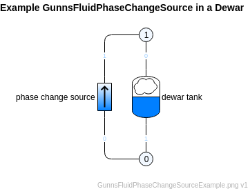
This link is connected between a liquid node on port 0 and a gas node on port 1, similar to GunnsFluidPhaseChangeConductor. An example of this link used along with a GunnsFluidAccumGas to model a dewar is illustrated below. Note that the liquid & gas port # convention of this link is opposite that of the accumulator link:

Port Connection Rules (These are limitations on the port connection to nodes that the link enforces in run-time):
- Port 0 must connect to either a liquid node or the Ground node.
- Port 1 must connect to either a gas node or the Ground node.
Other Rules (These are extra rules you should always try to follow):
- See the rules in GunnsFluidPhaseChangeConductor about helping to conserve mass.
Configuration Data Parameters:
- liquidType (default = FluidProperties::NO_FLUID, must be a liquid type present in the network, i.e. FluidProperties::GUNNS_OXYGEN): same as GunnsFluidPhaseChangeConductor.
- gasType (default = FluidProperties::NO_FLUID, must be a gas type present in the network, i.e. FluidProperties::GUNNS_O2): same as GunnsFluidPhaseChangeConductor.
- efficiency (default = 0.0, must be in [-1,1]): this is the power efficiency of the modeled device. See the description of efficiency above. For heat sources, and not electrical power sources, you would normally use +1 or -1 here, depending on the sign convention of your heat source value.
Input Data Parameters:
- malfBlockageFlag (default = false): this is the initial activation flag of the flow blockage malfunction.
- malfBlockageValue (default = 0.0, must be in [0,1]): this it the initial value of the flow blockage malfunction. This malfunction blocks the input power. When active and this value is 1, input power is completely blocked and there is no flow. A value of 0 here has no effect.
- powerInput (default = 0.0 (W)): this is the initial input power, in Watts.
- N/A
- N/A