GunnsFluidSource - nasa/gunns GitHub Wiki

This link forces a mass flow rate between two nodes. The link does not modify any properties of the fluid passing through it.
This picture shows the various ways fluid sources can be connected to nodes, and one way they can't. Putting both ports on Ground is a good way to store spare links.
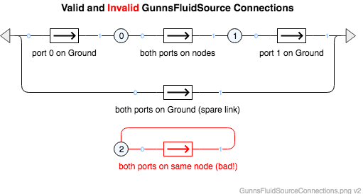
Port Connection Rules (These are limitations on the port connection to nodes that the link enforces in run-time):
- Ports 0 and 1 cannot connect to the same non-Ground node.
Other Rules (These are extra rules you should always try to follow):
- Do not mix fluid phases across the link. That is, both nodes should contain the same phase (gas or liquid), and not different phases.
Configuration Data Parameters:
- N/A
Input Data Parameters:
- malfBlockageFlag (default = false): Initial state of the blockage malfunction activation flag. This malfunction reduces the actual flow rate the flowDemand value.
- malfBlockageValue (default = 0.0, must be (0-1)): Initial state of the blockage malfunction activation value. A value of 0.0 is the same as no blockage at all, and 1.0 completely blocks all flow and isolates the port nodes from each other (although parallel flow paths still apply).
- flowDemand (default = 0.0 (kg/s), and non-zero magnitudes should be kept between E-15 and E+15): This is the initial source flow rate. Positive rates flow from port 0 to port 1, and negative rates flow from port 1 to port 0.
-
Pressure Stability: this link forces flow rate between nodes regardless of the network's
ability to accommodate the flow. This can be a source of instability - if a large mass of
flow is forced into a node that has low capacitance, the node pressure can blow up as the solver
tries to satisfy the fluid's state equation relating pressure and density. Liquid networks
are especially susceptible to this. This link makes no allowances for such problems, so care
must always be used with this link to ensure that the flow rate it forces is reasonable. These
are ways this is typically done:
- The "user", either manually or as another model aspect via simbus, drives this link's flowDemand itself, and actively modulates the demand based on network conditions.
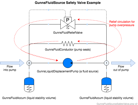
- It is common, especially in liquid systems, to place a safety GunnsFluidReliefValve parallel to the source link, to alleviate excess pressure on the flow outlet by circulating it back to the inlet (this is a common practice in the real-world with liquid displacement pumps). However, the relief valve doesn't respond to a pump exit overpressure until the next network step, so you still get a one-frame spike in pressure. Using an additional fluid conductor in parallel with the pump to model normal back-flow through internal seals also helps to reduce this pressure spike. Some flexible volume on the inlet & exit nodes is recommended for the relief valve pressure ports, and further reduces the pressure spike. This arrangement is shown here:
- N/A