GunnsElectPvRegShunt - nasa/gunns GitHub Wiki

This link models an output voltage regulator for a GunnsElectPvArray that uses shunting of array strings to control the output voltage, similar to the Sequential Shunting Units (SSU) in the ISS.
This link, paired with a GunnsElectPvArray, is intended to be an improvement over the old ISS SSU and SolarArray link pairing.
In this shunting control scheme, some of the array strings are tied to the regulator output channel until the demanded power load from downstream is met and the desired voltage setpoint begins to be exceeded -- then the remaining strings are shunted (short-circuited) to reduce their voltage and wasted power to safe levels.
This link allows the order in which the strings are loaded & shunted to be customized, or the order can be defaulted to the same order they're defined in the attached array.
This link has an execution order dependency on the GunnsElectPvArray it interfaces with. This link must be initialized and stepped after the array. This order can be established with proper setup in the GUNNS network, described below.
This link currently has 2 operating states, which it automatically switches between:
- REG: when the array can meet the demanded power load from the downstream circuit, the output voltage is regulated and the above string loading & shunting scheme is used. This link acts like a potential source on the output node, loads the array strings individually, a total load is placed on the input node that approximates the average array load, and the two nodes are not directly connected.
- OFF: when the link is disabled by command input, or when the array can't meet the demanded power load at the regulator voltage, or can't meed a minimum power output value. All strings are shunted and the output node is isolated and unregulated.
This link models the waste heat produced by its internal resistance and the shunted strings power.
This link can use optional GunnsSensorAnalogWrapper spotters for input and output voltage and current. Optional trip functions can also be used with or without these sensors.
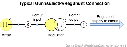
This is a two-port GUNNS link. The recommended use is pictured below:
- Port 0 is the input node, shared with the array output.
- Port 1 is the output node to the downstream circuit, whose voltage is controlled.
Order Dependency:
This link must run after the array in the network. This can be set up in the drawing in one of two ways:
- Select the regulator link. Then in the Arrange tab of the Draw.io Format Panel (right-hand side), click the To Front button.
- Simply adding the regulator onto the drawing after the array has been added. Cutting and re-pasting the regulator will do the same.
Port Connection Rules (These are limitations on the port connection to nodes that the link enforces in run-time):
- Ports 0 and 1 cannot be connected to the same non-Ground node.
Other Rules (These are extra rules you should always try to follow):
- The Port 0 input node should only be connected to this link, and one PV array. Make no other connections to it.
Configuration Data Parameters:
- outputConductance (default = 0 (1/ohm), must be > 0): This is the conductance of the regulator output channel, also the inverse of the regulator's internal resistance. Lower values create more of a droop in the output voltage under increasing loads. The electrical current through this resistance contributes to the regulator's waste heat output.
- shuntConductance (default = 0 (1/ohm), must be > 0): This is the conductance of the load placed on each array string when it is shunted. The electrical current through this resistance contributes to the regulator's waste heat output. Strings are usually shunted through a high conductance (short-circuited) to keep this waste heat low.
- array (default = 0, must not be 0): This is the address of the GunnsElectPvArray link to be regulated. For an array named "PvArray", this syntax would be &network->PvArray.
- inCurrentSensor (default = 0): This is the address of the optional GunnsSensorAnalogWrapper to be used for the regulator's input current sensor. If no sensor is desired, leave this as 0. Otherwise provide the address of the spotter in the network. For example if the spotter is called "SarInAmpsSensor", then you'd use &network->SarInAmpsSensor here.
- inVoltageSensor (default = 0): similar to inCurrentSensor but for the input voltage sensor.
- outCurrentSensor (default = 0): similar to inCurrentSensor but for the output current sensor.
- outVoltageSensor (default = 0): similar to inCurrentSensor but for the output voltage sensor.
- inputOverCurrentTrip (default = 0 (amp)): This is the value above which the input current will cause the regulator to trip off. To enable this trip function, specify a non- zero value here. To disable this trip function, leave it zero.
- inputOverVoltageTrip (default = 0 (v)): Similar to inputOverCurrentTrip but for the input voltage.
- outputOverCurrentTrip (default = 0 (amp)): Similar to inputOverCurrentTrip but for the output current.
- outputOverVoltageTrip (default = 0 (v)): Similar to inputOverCurrentTrip but for the output voltage.
- outputUnderVoltageTrip (default = 0 (amp)): This is the value below which the output voltage will cause the regulator to trip off. To enable this trip function, specify a non- zero value here. To disable this trip function, leave it zero.
- tripPriority (default = 0, must >= 0): This specifies the priority for this link's trips relative to other link trip functions in the network. A value of zero will disable all trips. Above zero, lower values will trip first relative to other links. In general, an electrical system will be designed such that trips occur downstream first. Because this is a power source, this will probably trip after downstream links, so this would have a higher value than the downstream link's value.
-
mStringLoadOrder (Trick Input File only): This is an optional list of array
sections and strings that customizes the order in which the regulator loads and shunts the
strings. By default, the regulator will load them in increasing order of section & string
number. This list allows you to load them in any other order. When using this list, note the
following rules:
- Create the list from the Trick Input File by calling the link config data's addStringLoadOrder(section, string) method, once for each string in the array. The section and string numbers count from zero, and the string count is relative to the number of strings in the section.
- For example, to load an array having 3 sections of 2 strings each in reverse order
you'd have in the input file:
- simObject.network.netConfig.regulator.addStringLoadOrder(2, 1)
- simObject.network.netConfig.regulator.addStringLoadOrder(2, 0)
- simObject.network.netConfig.regulator.addStringLoadOrder(1, 1)
- simObject.network.netConfig.regulator.addStringLoadOrder(1, 0)
- simObject.network.netConfig.regulator.addStringLoadOrder(0, 1)
- simObject.network.netConfig.regulator.addStringLoadOrder(0, 0)
- You must have exactly one entry for every string in the array.
- Note that the array allows a different number of strings in each section, so this list must match the actual number of strings in each section.
- Duplicate entries will cause an error.
- Entries with bad section or string numbers will cause an error.
- This list is not set in GunnsDraw and you won't see it in the link shape data.
- To use the default loading order, simply ignore this list by making no entries to it.
Input Data Parameters:
- voltageSetpoint (default = 0.0 (v), must be > 0): Initial value of the regulated output voltage setpoint that the regulator tries to control to.
- powered (default = false): Initial powered flag for the regulator. false unpowers the regulator, and true powers it.
- enabled (default = false): Initial enable flag for the regulator. false disables the regulator, and true enables it.
- minOperatePower (default = 0.0 (W)): This is the minimum available power from the solar array at the voltageSetpoint voltage required for this regulator to operate. If the array can't make this minimum power, this regulator remains in the OFF state, and won't return to the REG state until the array can exceed this power. This is useful to keep the regulator from oscillating between REG and OFF states when the array is under low light conditions or is degraded. We recommend setting this to greater than zero and less than the array's maximum regulated output in full lighting conditions. The array's maximum regulated output at any time can be seen in this link's mPvBulkPowerAvail term.
- Runtime initialization error "array link not initialized before this link.": This error message appears in the H&S log if you've not set the proper order dependency between the array and this regulator. See the Order Dependency section above.
- N/A