GunnsElectPvArray - nasa/gunns GitHub Wiki

This link models a photovoltaic array containing parallel sections, each containing parallel strings of multiple photovoltaic cells in series. The entire array is modeled as an equivalent circuit supplying power to the terminal node. The link acts like a voltage source whose available supply depends on the lighting environment and the load placed on it by the downstream circuit.
Each section provides an environment interface to its contained strings. This environment interface contains ambient light level, facing towards the light source, shading, and structural temperature. The array can contain multiple sections, each with a different envrionment interface to its strings, for modeling complicated arrays that have panels with different facing, etc. Each section can have the same or a different number of strings.
The amount of voltage an array can create increases with the number of cells in each string. The amount of current an array can create increases with the number of strings in parallel. All strings have identical configuration, though their states can differ in run-time.
The strings include some diodes in series with the cells: a final blocking diode after the furthest downstream cell, and bypass diodes around groups of cells. The blocking diode prevents backflow of current into a string from a higher-voltage downstream circuit. The bypass diodes allow some functioning of the string when it is partially shaded, by bypassing current from lit cell groups around shaded cells groups. The total number of cells in each string and the number of cells in each bypass diode group are configurable.
The strings have malfunctions for modeling fractional degradation due to age or surface fouling, or complete failure of cell groups.
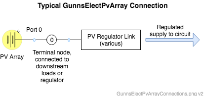
This link can be tied directly to the circuit. However, photovoltaic arrays will usually be connected to some kind of regulator that controls the voltage supplied to the circuit. Such regulators are modeled with different links -- see the available PV Regulator links for more information.
The GunnsElectPvArray link has one port, connected to the "terminal" (output) node that the array is to supply power to. The typical use is shown below. The type of PV Regulator link used will depend on the design of the real regulator you are modeling:
Port Connection Rules (These are limitations on the port connection to nodes that the link enforces in run-time):
- None. Port 0 can be connected to any node, even the Ground node. A regulator, if used, may have special requirements for how the array is connected.
Other Rules (These are extra rules you should always try to follow):
- N/A
Configuration Data Parameters:
- arrayNumSections (default = 0, must be > 0): This is the number of sections in the array. Each section provides a separate environment interface to its contained strings.
- arrayNumStrings (default = 0): This is the total number of strings in the array. By default, all sections will have the same number of strings; therefore this term must be a multiple of arrayNumSections. However, if the mNumStringsBySection list is provided (see below), then the total number of strings in the array is determined by that list, and this term isn't used. So set this term if you want each section to have the same number of strings, otherwise leave this zero and provide mNumStringsBySection instead.
- mNumStringsBySection (Trick Input File only): This is an optional integer pointer you can set in the Trick Input File to customize the number of strings in each section. It is not set in GunnsDraw so you won't see this term in the GunnsDraw link shape data. To use this feature, create an integer array in the input file of length equal to the number of sections, set each position in the array to the number of strings (>=1) in each section, and then set this pointer to the array.
- sectionSourceAngleExponent (default = 0.0, must be (0-10)): This is an exponent on the cosine function of the light source angle relative to the section surface. The section's strings produce power in proportion to cosexponent(angle). An exponent value of 1 creates a normal cosine curve. A lower value allows more power to be generated at off angles, whereas a higher value causes a larger fall-off of power with increasing off angle.
- sectionBacksideReduction (default = 0.0, must be (0-1)): This is the amount of reduction of power generation when the section is lit from the back side. A value of zero allows the section to generate the same power from either side. A value of 1 limits the section to only generate power when lit on the front side, and can generate no power from the back side.
- sectionSourceAngleEdgeOn (default = false): This flag allows the light source angle to the section to be defined from either the surface normal, or edge-on. Use false if the angle is relative to the surface normal, and true for edge-on.
- sectionRefSourceFluxMagnitude (default = 0.0 (W/m2)): This defines a reference value for the ambient light flux magnitude. It doesn't contribute to array power output; rather this is just a reference for updating a percent insolation term, to indicate to users how much light is on the panel during run-time. A good reference value is the mean solar flux in low-earth orbit = 1361 W/m2.
- stringBlockingDiodeVoltageDrop (default = 0.0 (v), must be >=0): This is the diode junction voltage drop across the blocking diode at the end of each string. Silicon diodes typically have a value of 0.6 v.
- stringBypassDiodeVoltageDrop (default = 0.0 (v), must be >=0): This is the diode junction voltage drop across each bypass diode. Silicon diodes typically have a value of 0.6 v.
- stringBypassDiodeInterval (default = 0, must be divisible in stringNumCells): This is the number of cells in each bypass diode group. If it is not desired to model any bypass diodes, then set this number equal to stringNumCells. This must be at least 1 and cannot be larger than stringNumCells. The number of bypass groups and diodes in the string will be stringNumCells divided by this number.
- stringNumCells (default = 0 (--), must be > 0): This is the number of cells in each string. A value of 1 models a single cell, and values > 1 model a string of cells wired in series.
- cellSurfaceArea (default = 0.0 (m2), must be > 0): This is the surface area of one side of each cell in the array.
- cellEfficiency (default = 0.0, must be (0-1)): This is the fraction of light power that is converted to electrical power by the cells. This does not include the losses in the shunt and series equivalent resistances. Typical values of real solar cells are around 0.2.
- cellSeriesResistance (default = 0.0 (ohm), must be > 0): This is the equivalent series resistance of each cell. A typical value for a cell is around 0.017 ohm.
- cellShuntResistance (default = 0.0 (ohm), must be > 0): This is the equivalent shunt resistance of each cell. A typical value for a cell is around 200 ohm.
- cellOpenCircuitVoltage (default = 0.0 (v), must be > 0): This is the maximum voltage that each cell can create. A typical value for a cell is around 0.6 v.
- cellRefTemperature (default = 0.0 (K), must be > 0): This is the reference temperature for temperature effect calculations. Temperature effects will be proportional to the difference between the actual panel tempeature during run-time, and this reference value.
- cellTemperatureVoltageCoeff (default = 0.0 (1/K)): This is the coefficient for the effect of temperature on open-circuit voltage of the cells. Typical solar cells have a value of -0.003 (1/K), which decreases open-circuit voltage by 0.3% per degree Kelvin.
- cellTemperatureCurrentCoeff (default = 0.0 (1/K)): This is the coefficient for the effect of temperature on short-circuit current of the cells. Typical solar cells have a value of 0.00065 (1/K), which increases short-circuit current by 0.065% per degree Kelvin.
Input Data Parameters:
- sectionSourceFluxMagnitude (default = 0.0 (W/m2), must be >= 0): Initial value of the actual light source flux, or surface power per unit area at the section's location. This would normally be driven in run-time from a radiative environment model, but can be initialized here.
- sectionSourceAngle (default = 0.0 (r)): Initial angle between the section surface and the vector to the light source. Depending on the sectionSourceAngleEdgeOn flag, this will either be relative to the surface normal vector, or edge-on to the surface.
- sectionSourceExposedFraction (default = 0.0 (--), must be (0-1)): Initial fraction of the section surface that is visible to the light source. Any value less than 1 means the section is partially shaded and produces less power. A value of 0 makes the section completely shaded and can produce no power.
- sectionTemperature (default = 0.0 (K), must be > 0): Initial temperature of the section for calculating the temperature effects.
- N/A
- N/A