GunnsElectPvRegConv - nasa/gunns GitHub Wiki
This link models an output voltage regulator for a GunnsElectPvArray that uses a DC-DC voltage converter to control the output voltage, similar to the Solar Array Regulator (SAR) in the AMPS project.
This link, paired with a GunnsElectPvArray, is intended to be an improvement over the old GunnsSolarArrayRegulator and SolarArray link pairing.
The DC-DC voltage conversion is configured with a conversion efficiency, and an upper limit to the output/input voltage ratio. No lower limit is applied -- the output voltage can be lowered to near zero. Losses due to the conversion efficiency are output as waste heat.
This link has an execution order dependency on the GunnsElectPvArray it interfaces with. This link must be initialized and stepped after the array. This order can be established with proper setup in the GUNNS network, described below.
Rather than an input node, this regulator has a pointer to interact with the array directly. Since this regulator and the array calculate the interfacing state between them, array strings are always tied to a common output (the input to the regulator), and there is never a need to bypass the regulator and connect the array directly to the downstream circuit, a network node between the regulator and array is wasteful, so not used.
This link has 4 operating states, which it automatically switches between:
- REG: when the array can meet the demanded power load from the downstream ciruit, the output voltage is regulated. This link acts like an ideal voltage source on the output node.
- SAG: when the array can't meet the demanded power load at the regulated voltage or the regulator can't boost the array voltage up to the regulated voltage, but the array is still on the open-circuit side of its I-V performance curve, the output voltage of this regulator begins to drop below the regulated value. This link acts like a (non-ideal) voltage source on the output node.
- SHORT: same as SAG, except the array is now on the short-circuit side of its I-V curve. This happens at high loads on the regulator. The regulator output voltage drops more steeply.
- OFF: when the link is disabled by command input, or the downstream circuit is at a higher voltage than the regulator setpoint. The link places a very small leak conductance on the output node to Ground.
This link can use optional GunnsSensorAnalogWrapper spotters for input and output voltage and current. Optional trip functions can also be used with or without these sensors.
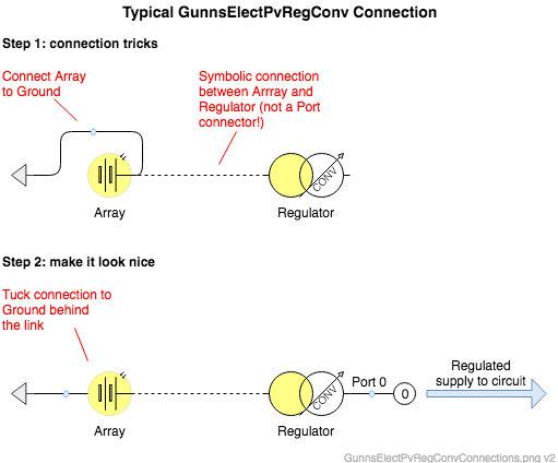
This is a one-port GUNNS link. The recommended use is pictured below:
- Port 0 is the output node to the downstream circuit, whose voltage is controlled.
- The array's output port is connected to Ground.
- This link doesn't actually connect to the array through a node, but we can add the connection lines anyway, for clarity. This makes the drawing look more like a circuit that your users will understand, as shown below:
Order Dependency:
This link must run after the array in the network. This can be set up in the drawing in one of two ways:
- Select the regulator link. Then in the Arrange tab of the Draw.io Format Panel (right-hand side), click the To Front button.
- Simply adding the regulator onto the drawing after the array has been added. Cutting and re-pasting the regulator will do the same.
Port Connection Rules (These are limitations on the port connection to nodes that the link enforces in run-time):
- N/A.
Other Rules (These are extra rules you should always try to follow):
- Connect the array link directly to Ground, with no intervening nodes or links.
Configuration Data Parameters:
- voltageConvLimit (default = 0, must be >= 1): This is the maximum amount that the converter can boost the input voltage from the array, as a ratio to the input voltage. So if this value is 1.5 and the array has a maximum output voltage of 12, then the maximum voltage this regulator could output would be 18.
- voltageConvEfficiency (default = 0, must be (0-1)): This is the power efficiency of the DC-DC voltage conversion. A value of 1 is 100% efficient, meaning there are no power losses in the conversion, and power in = power out. A value < 1 makes power in > power out, and the difference is modeled as waste heat.
- array (default = 0, must not be 0): This is the address of the GunnsElectPvArray link to be regulated. For an array named "PvArray", this syntax would be &network->PvArray.
- inCurrentSensor (default = 0): This is the address of the optional GunnsSensorAnalogWrapper to be used for the regulator's input current sensor. If no sensor is desired, leave this as 0. Otherwise provide the address of the spotter in the network. For example if the spotter is called "SarInAmpsSensor", then you'd use &network->SarInAmpsSensor here.
- inVoltageSensor (default = 0): similar to inCurrentSensor but for the input voltage sensor.
- outCurrentSensor (default = 0): similar to inCurrentSensor but for the output current sensor.
- outVoltageSensor (default = 0): similar to inCurrentSensor but for the output voltage sensor.
- inputOverCurrentTrip (default = 0 (amp)): This is the value above which the input current will cause the regulator to trip off. To enable this trip function, specify a non- zero value here. To disable this trip function, leave it zero.
- inputOverVoltageTrip (default = 0 (v)): Similar to inputOverCurrentTrip but for the input voltage.
- outputOverCurrentTrip (default = 0 (amp)): Similar to inputOverCurrentTrip but for the output current.
- outputOverVoltageTrip (default = 0 (v)): Similar to inputOverCurrentTrip but for the output voltage.
- outputUnderVoltageTrip (default = 0 (amp)): This is the value below which the output voltage will cause the regulator to trip off. To enable this trip function, specify a non- zero value here. To disable this trip function, leave it zero.
- tripPriority (default = 0, must >= 0): This specifies the priority for this link's trips relative to other link trip functions in the network. A value of zero will disable all trips. Above zero, lower values will trip first relative to other links. In general, an electrical system will be designed such that trips occur downstream first. Because this is a power source, this will probably trip after downstream links, so this would have a higher value than the downstream link's value.
Input Data Parameters:
- voltageSetpoint (default = 0.0 (v), must be > 0): Initial value of the regulated output voltage setpoint that the regulator tries to control to.
- voltageSetpointDelta (default = 0.0 (v)): Initial value of the voltage setpoint delta command.
- powered (default = false): Initial powered flag for the regulator. false unpowers the regulator, and true powers it.
- enabled (default = false): Initial enable flag for the regulator. false disables the regulator, and true enables it.
- Runtime initialization error "array link not initialized before this link.": This error message appears in the H&S log if you've not set the proper order dependency between the array and this regulator. See the Order Dependency section above.
- N/A