Synchronous Counters - mbits-mirafra/digitalDesignCourse GitHub Wiki
| Sr.no | Synchronous Counters |
|---|---|
| 1 | Synchronous up/down counter |
| 2 | Mod 4 ring counter |
| 3 | Mod 8 jhonson counter |
| 4 | Mod 7 twisted ring counter |
| 5 | Gray Counter |
Synchronous Up/Down Counter
What is Synchronous Up/Down Counter?
A Synchronous Up/Down counter is a bidirectional counter that has the ability to count in both directions either to or from some preset value as well as zero. The up/ down counter has “Up” and “Down” count modes by having 2x1 Mux, which are used to detect the appropriate bit conditions for counting operation. It is termed as synchronous because a single clock is given to all the flip flops.
How Synchronous Up/Down Counter Works?
Let us first see the design of synchronous up/down counter:
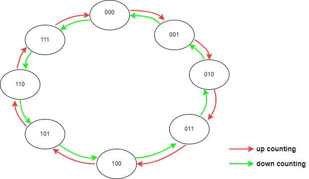
The state diagram of up/down counting:
The Excitation table is:

We obtain TA, TB, TC values by comparing the present state outputs with next state outputs. Whenever the next state has been toggled the T values will be high or else the T will be low.
K-map: By referring the above Excitation table the respective k-maps can be constructed to obtain boolean expression for TA, TB and TC.

Circuit diagram: From the expressions obtained we can design the circuit.

Block diagram of a 4 bit synchronous up/down counter with count enable:
Fig. 1. 4-bit Synchronous Up/Down Counter
Up/down’ is the control signal which determines the operation. When up/down’ signal is high, the output of the first AND gate will be high. This output is connected as input to the first AND gate of the next state Flip Flop. Thus Q0 will be passed as input to the second flip flop facilitating up counting. If up/down’ signal is low then the output of the second AND gate will be high and is connected as input to the second AND gate of next state flip flop allowing Q0’ to be passed.
Truth Table:

Fig. 2. Truth table of 4-bit Synchronous Up/Down Counter
The above table shows the flow of up counting from decimal 0 to 15 and the flow of down counting from decimal 15 to 0.
Timing diagram:
Up counting is from left to right, whereas down counting is from right to left.
Fig. 3. Timing diagram of 4-bit Synchronous Up/Down Counter
Designing using D Flip Flop
Synchronous up/down counter can also be designed using D Flip Flop, However it isn't optimal
The state diagram of up/down counting remains the same as earlier
The Excitation table is:

K-map:
By referring the above Excitation table the respective k-maps can be constructed to obtain boolean expression for DA, DB and DC.

Circuit diagram: From the expressions obtained we can design the circuit.
Why Synchronous Up/Down Counter is used?
Synchronous up/down counters are commonly used in digital circuits for various applications because they provide the ability to count up or down based on a control signal, making them versatile and useful in a wide range of scenarios. They are capable of counting in either direction through any given count sequence and they can be reversed at any point within their count sequence by using an additional control input. The up/down counter can be cascaded within the high-speed mode.
When Synchronous Up/Down Counter is used?
Synchronous counters are typically used in situations where precise timing is required, such as in digital signal processing, data communication, and control systems. Because each flip-flop in the counter is triggered at the same time, synchronous counters are less susceptible to timing errors than asynchronous counters, which can have timing variations between the different flip-flops. Some applications are:
- Timing and Frequency Generation: Synchronous up-down counters are used in digital clocks, timers, and frequency generators to count the number of clock cycles and generate accurate timing signals.
- Digital Signal Processing: Synchronous up-down counters are used in digital signal processing applications such as digital filters, convolution, and correlation operations.
- Test and Measurement Equipment: Synchronous up-down counters are used in test and measurement equipment to count the number of events or cycles and calculate frequency, period, and time intervals
Advantages of Synchronous Up/Down Counter?
- Precise timing: Synchronous counters use a clock signal to synchronize the timing of the individual flip-flops that make up the counter, resulting in precise and consistent timing of the counter's operation.
- Flexibility: Synchronous up-down counters can count up or down, depending on the direction signal applied to the control input. This flexibility makes them suitable for a wide range of applications.
- Improved reliability: Synchronous counters are less susceptible to timing errors and glitches than asynchronous counters, which can have timing variations between the different flip-flops. This makes synchronous up-down counters more reliable and less prone to errors.
- Reduced power consumption: Synchronous counter can perform both up and down counting, hence the number of flip flops can be reduced resulting in lesser power consumption.
Disadvantages of Synchronous Up/Down Counter?
- Complexity: Synchronous up-down counters are more complex than asynchronous counters due to their requirement for a clock signal and the need for additional logic gates to implement the up-down functionality. This complexity can make them more difficult to design and troubleshoot.
- Limited frequency range: Synchronous up-down counters may have a limited frequency range due to the maximum speed of the clock signal and the propagation delay of the logic gates. This can limit their use in applications that require high-frequency counting.
Mod 4 Ring Counter (One Hot Counter)
What is Ring Counter?
A ring counter is a type of digital counter circuit that can shift a single "1" bit through a sequence of connected flip-flops or shift registers, forming a closed loop or ring. Each flip-flop in the ring is connected in such a way that its output is connected to the input of the next flip-flop in the ring, with the output of the last flip-flop connected to the input of the first flip-flop.
How Ring Counters work?
Block diagram:

Fig 4. Mod 4 Ring Counter
- An ‘N’ bit Ring counter performs the Serial In - Parallel Out shift operation but, the only difference is that the output of rightmost D flip-flop is given as input of leftmost D flip flop instead of applying data from outside.
- Therefore, Ring counter produces a sequence of states (pattern of zeros and ones) and it repeats for every ‘N’ clock cycles.
- Using pre-set and clear input initial value of the output is defined.
- The first flipflop output is set to logic 1 and all other flipflop output is set to logic 0. The initial status of the D flip-flops in the absence of clock signal is 1000. This status repeats for every four negative edge transitions of clock signal.
Truth table

Fig 5. Truth Table of Mod 4 Ring Counter
Timing diagram

Why Mod 4 Ring Counter?
Applications
-
LED drivers: Ring counters are often used in LED drivers to control the illumination of a series of LEDs. By generating a sequence of pulses, the ring counter can activate each LED in turn, creating a blinking or chasing effect.
-
Traffic light controllers: These counters can be used to control the sequence of traffic lights at a junction. At a time one traffic light can be green and remaining three are red. After few minutes the green light shifts to other direction of the traffic and remaning three becomes red and so on. It is cyclic and follows the ring pattern.
Advantages of Ring Counters
-
Simplicity: Ring counters are relatively simple to implement using a chain of flip-flops connected in a loop. This makes them a cost-effective and efficient solution for generating sequences of digital signals.
-
Low power consumption: Ring counters typically consume less power than other types of digital circuits, such as ripple counters or synchronous counters. This is because they have a limited number of states and require less clocking and gating.
Disadvantages of Ring Counter
-
Limited sequence length: The number of states in a ring counter is limited by the number of flip-flops in the chain. This means that the sequence length is also limited, which may not be sufficient for some applications.
-
Propagation delays: Ring counters are subject to propagation delays, which can cause timing errors if not properly accounted for in the design. This can be particularly problematic for high-speed applications that require precise timing.
-
Difficult to reset: Resetting a ring counter can be challenging because the output of the last flip-flop is connected to the input of the first flip-flop in the chain.
Mod 8 Johnson Counter
What is Johnson Counter?
A Johnson counter is a type of shift register that is similar to a ring counter, but with the added feature of complementing the output at every other stage. It consists of a series of flip-flops connected in a loop, with the output of each flip-flop connected to the input of the next flip-flop in the chain. Johnson counter is also called as Twisted Ring counter and switch tail Ring counter
How Johnson Counter works?
Block diagram

- The operation of Johnson counter is similar to that of Ring counter but, the only difference is that the complemented output of rightmost D flip-flop is given as input of leftmost D flip-flop instead of normal output.
- Therefore, ‘N’ bit Johnson Ring counter produces a sequence of states (pattern of zeros and ones) and it repeats for every ‘2N’ clock cycles.
- Using clear input initial value of the output is defined.
- The initial status of the D flip-flops in the absence of clock signal is 0000. This status repeats for every eight negative edge transitions of clock signal.
Truth table

Fig 6. Truth table of Mod 8 Johnson Counter
Timing diagram


Why Johnson Counters?
The versatility ,simpler design and cascading of Johnson Counter is far better than Ring Counters. And also the number of flipflop used is comparatively lesser than the Ring counter
When Johnson Counter?
Applications:
- Random number generators: By carefully selecting the feedback connections in a Johnson counter, it is possible to generate a sequence of pseudo-random numbers that can be used in a variety of applications, such as cryptography or simulations. If number of flip-flops are increased then the states can be increased and this can give a huge set of random numbers.


Advantages of Johnson Counters
- High-speed operation: Johnson counters are often used in high-speed applications, where their simple design and low power consumption can be an advantage.
Disadvantages of Johnson Counter
- Limited binary count: Johnson counters can only count up to half the maximum count possible with a binary counter of the same number of flip-flops. For example, a 4-bit binary counter can count up to 16, while a 4-bit Johnson counter can only count up to 8. This limits their usefulness in applications where a full binary count is required.
Mod 7 twisted ring counter
let us design Mod 7 Twisted Ring Counter
Step 1: Consider the Truth table of Mod 7 twisted ring counter where it is similar to jhonson counter where only the difference is the 1111 state is not present in this counter
Truth table

Step 2: using truth table, write the excitation table

Step 3: write the K-maps for all the D flip flop inputs and write the corresponding equations using the k-maps


Step 4: write the circuit diagram using the equations obtained using k-maps
Circuit diagram

What is mod 7 twisted ring counter?
- It is a type of counter circuit which can count 7 different states(mod 7), the inputs to the flipflop are non linear (twisted) and the chain of connected flip flops(ring), hence the name mod 7 twisted ring counter.
- In a mod 7 twisted ring counter, the output values change on each clock cycle, with the circuit cycling through all 7 states before repeating the sequence. This type of counter can be implemented using flip-flops.
- The outputs of the flip-flops are then connected in a circular pattern, with the output of each flip-flop feeding into the input of the next flip-flop in the sequence. The specific pattern of connections is what gives the counter its "twisted" characteristic.
How mod 7 twisted ring counter works?
- In a mod 7 twisted ring counter, the output Q' of the third and fourth flip-flops are connected to an AND gate, and the output of the AND gate is connected to the input of the first flip-flop.
Timing Diagram

The truth table for the same is shown in above table Total it has 7 states , the circuit arrangement is done in such a fashion where we grt the above output when clocks are given
When Mod 7 twisted ring counters are used?
- Audio equipment: Mod 7 twisted ring counters can be used in audio equipment, such as synthesizers and drum machines, to generate complex rhythms and patterns. By combining multiple counters and controlling the clock signals, musicians and sound engineers can create intricate and unique sequences of sounds and beats.
- Cryptographic Key Generator: This application uses a twisted mod 7 ring counter to generate a stream of random bits that can be used as a key stream in a stream cipher. The output of the counter is combined with plaintext to generate ciphertext, or with ciphertext to generate plaintext. The use of the counter ensures that the key stream is unpredictable and non-repeating, enhancing the security of the ciphe
- Random Number Generator: This application uses a twisted mod 7 ring counter to generate a stream of random bits that can be used as a random number generator. The output of the counter can be fed into an algorithm that generates random numbers in a specified range, which can be used in various applications such as games and simulations.
why mod 7 twisted ring counter used?
These are mainly chosen because of Specific counting sequence: The mod 7 twisted ring counter produces a counting sequence of 0, 8, 12, 14, 7, 3. This can be useful in applications where a specific sequence is required.
Advantages:
-
Simple design: The twisted ring counter has a simple design, making it easy to implement and maintain
-
Synchronous operation: The twisted ring counter operates synchronously with the clock signal, ensuring that the counter's outputs change only at the rising or falling edge of the clock signal and minimizing the risk of data loss or errors.
Disadvantages:
-
Limited counting range: The mod 7 twisted ring counter can only count up to 7 before resetting back to 1. This may be a limitation in some applications where a larger counting range is required.
-
Precise timing requirements: The mod 7 twisted ring counter requires precise timing of the clock signal to function properly. This can be difficult to achieve in some systems, especially at high clock frequencies. If the timing is not precise, the counter may produce incorrect output values or fail to count properly.
Gray Counter
State Diagram for Gray Counter

Truth table

Circuit Diagram
