Shift register by using other flipflop - mbits-mirafra/digitalDesignCourse GitHub Wiki
SISO by using T flipflop
SISO Shift register diagram is shown below which includes 4-T flip-flops. At first we need to convert the T flipflop into D. So these FFs are synchronous through each other because the equal CLK signal is applied in each Flip Flop.
(https://github.com/mbits-mirafra/digitalDesignCourse/wiki/T-FLIP-FLOP-TO-D-FLIP-FLOP - Refer to know about the coversion from T to D flipflop).
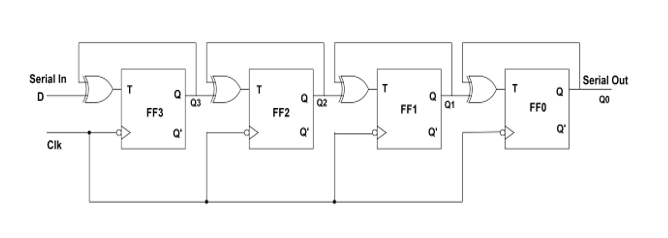
This is a shift right mode circuit which means when the data i/p is given at the left end of the flip flop then the stored bit can be shifted to the right side to generate serial output.
- Shifting by taking the LSB first
- Initially, the circuit must be set to reset mode. So the output provided by all the registers will be “0000”.
- Let us take an example of the 1111 binary number. The input is applied to shift register by taking LSB first and lastly the MSB.
- In this example the LSB bit is "1" and the MSB bit is "1". First, the high signal(LSB bit) is used as input to the XOR gate which is connected to the first flipflop FF3. Currently the T flipflop having an output of "0". So this zero will come into the input and it does XOR operations. The output from the XOR