Register Transfer Level - mbits-mirafra/digitalDesignCourse GitHub Wiki
RTL DESIGN
What is RTL design?
- RTL design or Register Transfer Level design is a method by which we can transfer data from one register to another
- RTL (Register-Transfer Level) design is a methodology used in digital circuit design that describes the behavior of a digital circuit at the register-transfer level of abstraction
- This means that the digital circuit is described in terms of registers, transfer functions, and combinational logic
- Constructing a digital design using Combinational and Sequential circuits in HDL like Verilog or VHDL which can model logical and hardware operation
Why RTL is needed?
- For understanding the complex operation performed in any digital systems we should understand RTL first
- RTL design allows designers to create digital circuits that are easier to understand, debug, and verify
- It also allows for faster design iteration, as changes can be made at the RTL level rather than requiring changes to be made at the gate level
- Register-transfer-level abstraction is used in HDL to create high-level representations of a circuit, from which lower-level representations and ultimately actual wiring can be derived
When to use RTL design?
As long as the system is simple there will not be any problem with the design but as the design becomes more complex we need to partition the whole system into smaller subsystems called modules. Modules are constructed using registers, multiplexers, decoders, etc. At this time RTL design is used.
RTL (Register-Transfer Level) design is a digital design technique used to create complex digital circuits. Here are a few examples of RTL design:
- Adder/Subtractor: An RTL design of an adder/subtractor circuit can perform both addition and subtraction operations on binary numbers
- Finite State Machine (FSM): RTL designs of FSMs are commonly used in digital systems that require sequential logic, such as in control units of processors
- Multiplexer (MUX): An RTL design of a multiplexer selects one input from multiple inputs based on the control signals
RTL design tools:
- Xilinx/AMD- Vivado
- Intel /Altera -Quartus
- Synopsys -RTL Architect
- Cadence -Genus
RTL method uses a set of expressions and statements to resemble the statements used in the programming language. In digital systems if we have to perform any operation we have to specify some things:
- Set of registers in the system.
- Binary–coded information in the registers.
- Inter register transfer operation
- Arithmetic operation
- Logical operation
- Shift operation
- Control functions.
Let us consider an example :
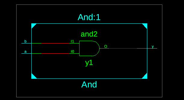
And Gate
module behavioral_and(input a,input b,output reg y );

always @(*) begin
if (a && b) begin // if both inputs are 1
    y = 1; // output is 1
end
else begin // if either input is 0
    y = 0; // output is 0
end
end

endmodule
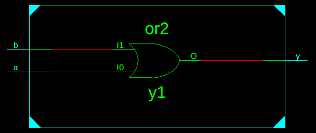
Or Gate
module OR_2_behavioral (output reg Y, input A,input B);
always @ (A or B) begin
if (A == 1'b0 & B == 1'b0) begin
    Y = 1'b0;
end
else
    Y = 1'b1;
end
endmodule
Nand gate
module NOR_2_behavioral (output reg Y, input A, input B);
always @ (A or B) begin
if (A == 1'b0 & B == 1'b0) begin
    Y = 1'b1;
end
else
    Y = 1'b0;
end
endmodule
Nor gate
module NOR_2_behavioral (output reg Y,input A,input B);
always @ (A or B) begin
if (A == 1'b0 & B == 1'b0) begin
    Y = 1'b1;
end
else
    Y = 1'b0;
end
endmodule
Not gate
module not_gate(input a, output reg y);

always @(a)
begin
if(a == 1'b0)
begin
y = 1b'1;
end
else
y = 1b'0;
end

endmodule
2:1 Mux
module mux2_1(sel,inp,out);
input sel;
input [1:0] inp;
output reg out;
always @(*)
begin
case(sel)
    1'b0 : out = inp[o];
    1'b1 : out = inp[1];
    endcase
end
endmodule
4:1 Mux
module mux4_1(sel,inp,out);
input [1:0]sel;
input [3:0]inp;
output reg out;
always @(*)
begin
case(sel)
    2'b00 : out = inp[o];
    2'b01 : out = inp[1];
    2'b10 : out = inp[2];
    2'b11 : out = inp[3];
    endcase
end
endmodule
8:1 Mux
module mux8_1(sel,inp,out);
input [2:0]sel;
input [7:0]inp;
output reg out;
always @(*)
begin
case(sel)
    3'b000 : out = inp[o];
    3'b001 : out = inp[1];
    3'b010 : out = inp[2];
    3'b011 : out = inp[3];
    3'b100 : out = inp[4];
    3'b101 : out = inp[5];
    3'b110 : out = inp[6];
    3'b111 : out = inp[7];
    endcase
end
endmodule
1:2 Demux
module demux1_2(sel, A, out);
input sel, A;
output [1:0] out;
always @(*)
begin
case(sel)
    1'b0 : out[0] = A;
    1'b1 : out[1] = A;
endcase
end
endmodule
1:4 Demux
module demux1_4(sel, A, out);
input [1:0] sel;
input A;
output reg [3:0] out;
always @(*)
begin
case(sel)
    2'b00 : out[0] = A;
    2'b01 : out[1] = A;
    2'b10 : out[2] = A;
    2'b11 : out[3] = A;
endcase
end
endmodule
1:8 Demux
module demux1_8(sel, A, out);
input [2:0] sel;
input A;
output reg [7:0] out;
always @(*)
begin
case(sel)
    3'b000 : out[0] = A;
    3'b001 : out[1] = A;
    3'b010 : out[2] = A;
    3'b011 : out[3] = A;
    3'b100 : out[4] = A;
    3'b101 : out[5] = A;
    3'b110 : out[6] = A;
    3'b111 : out[7] = A;
endcase
end
endmodule
Half Adder
module half_adder(a,b,sum,cout);
input a,b;
output reg sum,cout; // sum and carry

always @(*)
begin
case ({a,b})
2'b00: sum = 0;
2'b01: sum = 1;
2'b10: sum = 1;
2'b11: sum = 0;
default : sum = 0;
endcase

case ({a,b})
2'b00: cout = 0;
2'b01: cout = 0;
2'b10: cout = 0;
2'b11: cout = 1;
default : cout = 0;
endcase
end
endmodule
Full Adder
module full_adder(input a,input b,input cin,output reg s,output reg cout);

always @(a or b or cin) begin
// Truth table for the sum output
case ({a, b, cin})
  3'b000: s = 1'b0;
  3'b001: s = 1'b1;
  3'b010: s = 1'b1;
  3'b011: s = 1'b0;
  3'b100: s = 1'b1;
  3'b101: s = 1'b0;
  3'b110: s = 1'b0;
  3'b111: s = 1'b1;
endcase

// Truth table for the carry out output
case ({a, b, cin})
  3'b000: cout = 1'b0;
  3'b001: cout = 1'b0;
  3'b010: cout = 1'b0;
  3'b011: cout = 1'b1;
  3'b100: cout = 1'b0;
  3'b101: cout = 1'b1;
  3'b110: cout = 1'b1;
  3'b111: cout = 1'b1;
endcase
end

endmodule
Half Subtractor
module half_subtractor(a,b,diff,borrow);
input a,b;
output reg diff,borrow;

always @(*)
begin
case ({a,b})
2'b00: diff = 0;
2'b01: diff = 1;
2'b10: diff = 1;
2'b11: diff = 0;
default : diff = 0;
endcase

case ({a,b})
2'b00: borrow = 0;
2'b01: borrow = 1;
2'b10: borrow = 0;
2'b11: borrow = 0;
default : borrow = 0;
endcase
end
endmodule
Full Subtractor
module full_subtractor(input a,input b,input bin,output reg d, output reg bout);

always @(a or b or bin)
begin
case ({a, b, bin})
  3'b000: d = 1'b0;
  3'b001: d = 1'b1;
  3'b010: d = 1'b1;
  3'b011: d = 1'b0;
  3'b100: d = 1'b1;
  3'b101: d = 1'b0;
  3'b110: d = 1'b0;
  3'b111: d = 1'b1;
endcase

case ({a, b, bin})
  3'b000: bout = 1'b1;
  3'b001: bout = 1'b1;
  3'b010: bout = 1'b1;
  3'b011: bout = 1'b0;
  3'b100: bout = 1'b0;
  3'b101: bout = 1'b0;
  3'b110: bout = 1'b0;
  3'b111: bout = 1'b1;
endcase
end

endmodule
SR Flip Flop
module srff_behave(s,r,clk, q, qbar);
input s,r,clk;
output reg q, qbar;

always@(posedge clk)
begin

if(s == 1)
begin
q = 1;
qbar = 0;
end
else if(r == 1)
begin
q = 0;
qbar =1;
end
else if(s == 0 & r == 0)
begin
q <= q;
qbar <= qbar
end
end
endmodule
D Flip Flop
module dff (clk, reset, d, q, qb);
input clk;
input reset;
input d;
output q;
output qb;
reg q;
assign qb = ~q;
always @(posedge clk or posedge reset)
begin
if (reset)
begin
q <= 1'b0;
end
else
begin
q <= d;
end
end
endmodule
JK Flip Flop
module jk_flip_flop(input j,input k,input clk,output reg q);

always @(posedge clk) begin
if (j && ~k) // Set
q <= 1'b1;
else if (~j && k) // Reset
q <= 1'b0;
else if (j && k) // Toggle
q <= ~q;
end

endmodule
T Flip Flop
module t_flip_flop(input t,input clk,output reg q );
always @(posedge clk) begin
if (t) // Toggle
q <= ~q;
end
endmodule
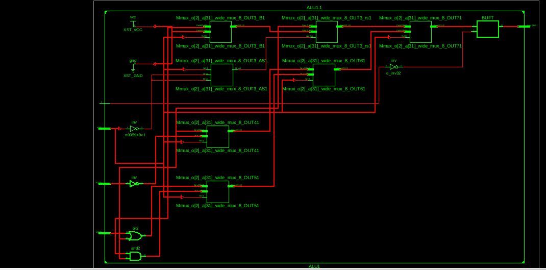
ALU
module alu( input [31:0] a,b, input [2:0] o, input e,output [31:0] aluout );
reg [31:0] aluresult;
assign aluout=aluresult;
always@(*) begin
if(e) begin
case(o)
3'b000: aluresult=a+b;
3'b001: aluresult=a-b;
3'b010: aluresult=a+1;
3'b011: aluresult=a-1;
3'b100: aluresult=a;
3'b101: aluresult=~a;
3'b110: aluresult=a|b;
3'b111: aluresult=a&b;
endcase
end
else
aluresult=32'bz;
end
endmodule