MSI Logic: Multiplexer, encoder, decoder - mbits-mirafra/digitalDesignCourse GitHub Wiki
Combinational circuit
The output is a pure function of the present input only.
Types of combinational logic circuits, such as Multiplexer, De-multiplexer, Decoder, Encoder,Adder, Subtractor,Comparator,Divider, Multipler.
Multiplexer
A multiplexer is defined as a combinational circuit that selects one of several data inputs and forwards it to the output. A multiplexer has 2^n input lines,n select lines and a single output line. The inputs to a multiplexer can be analog or digital. Multiplexers that are built from transistor and relays are termed as analog multiplexers which are used in analog applications. Multiplexers that are built from logic gate termed as digital multiplexers which are used in digital applications. The multiplexer or MUX is a digital switch, also called as data selector.
why multiplexer?
In digital systems, many times it is necessary to select a single data line from several data-input lines and the data from the selected data input line should be available on the output line. The digital circuit which does this task is a multiplexer.
A multiplexer reduces the number of wires used.Hence it reduces the circuit complexity and overall cost.
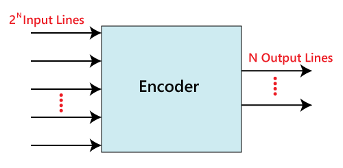
The below figure shows the block diagram of a multiplexer consisting of 2^N input lines, N selection lines and one output line.
When Enable=0,irrespective of the input the output is zero always.
When Enable=1,the data at the selected input appears as output.

The equation for Number of Selection lines given below
Number of selection line =log2(Number of input )
and also we can find Number of input by using following equation
Number of input= 2 ^ (Number of selection line)
For example,
for 4 :1 mux the Number of selection lines =log2(4) = 2
for 2 selection lines the number of inputs=2^2 =4
Type of Multiplexer
| Sr.no | topics |
|---|---|
| 1 | 2-to-1 |
| 2 | 4-to-1 |
| 3 | 8-to-1 |
2 to 1 Multiplexer
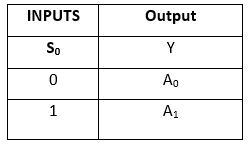
In 2×1 multiplexer, there are only two inputs, i.e., A0 and A1, 1 selection line, i.e., S0 and single outputs, i.e., Y. On the basis of the combination of inputs which are present at the selection lin e S0, one of these 2 inputs will be connected to the output.
Block Diagram
Truth Table
Logical expression
Y=S0'.A0+S0.A1

4×1 multiplexer
In the 4×1 multiplexer, there is a total of four inputs, i.e., A0, A1, A2, and A3, 2 selection lines, i.e., S0 and S1 and single output, i.e.,Y. On the basis of the combination of inputs that are present at the selection lines S0 and S1, one of these 4 inputs are connected to the output.
Block Diagram
Truth Table
logical expression
Y=S1' S0' A0+S1' S0 A1+S1 S0' A2+S1 S0 A3
Logical circuit
8 to 1 Multiplexer
In the 8 to 1 multiplexer, there are total eight inputs, i.e., A0, A1, A2, A3, A4, A5, A6, and A7, 3 selection lines, i.e., S0, S1and S2 and single output, i.e., Y. On the basis of the combination of inputs that are present at the selection lines S0, S1, and S2, one of these 8 inputs are connected to the output.
Block Diagram
Truth Table
logical expression
Y=S0'.S1'.S2'.A0+S0.S1'.S2'.A1+S0'.S1.S2'.A2+S0.S1.S2'.A3+S0'.S1'.S2 A4+S0.S1'.S2 A5+S0'.S1.S2 .A6+S0.S1.S3.A7
Logical circuit
6 to 1 Multiplexer
To make an 8:1 mux work as a 6:1 mux, we can tie the two most significant input lines of the 8:1 mux to either ground or VCC. This effectively eliminates those two input lines and leaves you with six remaining inputs, which can be used to implement a 6:1 mux. The select lines of the 8:1 mux should be adjusted to only select from the remaining six input lines.
Block Diagram:

Truth table:

logical expression
Y=S0'.S1'.S2'.A0+S0.S1'.S2'.A1+S0'.S1.S2'.A2+S0.S1.S2'.A3+S0'.S1'.S2 A4+S0.S1'.S2.A5
Logical circuit

Advantages of a Multiplexer
A multiplexer reduces the number of wires used. Hence it reduces the circuit complexity and overall cost. Multiplexer does not need the k-maps (Karnaugh map) and simplification.
Disadvantages of multiplexer
Additional delays required within switching ports & I/O signals which propagate throughout the multiplexer. The controlling of multiplexer can be done by using additional I/O ports.
Applications of a Multiplexer
Communication Systems

Multiplexers are used as a data selector to select one out of many data inputs in communication systems to transmit the various types of data (audio, video, etc.) at the same instant. Hence it increases the efficiency of the communication system by allowing various types of data into single transmission lines
Telephone Networks

In a telephone network, multiplexers can be used to transmit multiple audio signals into a single channel.
Implementation Of 4x1 Mux Using 2x1 Mux
We can implement 4x1 Mux using Three 2x1 Mux as show below.
Implementation Of 8x1 using Two 4x1 Mux and One 2x1 Mux

Implementation Of 8x1 using Seven 2x1 Mux

Implementation Of 16x1 using 4x1 Mux
We can implement 16x1 Mux using Five 4x1 Mux as show below.

Implementation Of 16x1 using two 8x1 Mux and One 2x1 Mux

De-multiplexer
A De-multiplexer is a combinational circuit that has only 1 input line ,N select line and 2N output lines. Demultiplexer is also known as data distributor
Why De-multiplexer?
In digital systems, many times it is necessary to select a multiple data line from one data-input lines and the data from the selected data input line should be available on the output line. The digital circuit which does this task is a de-multiplexer.
Type of De-multiplexer (De-mux)
| Sr.no | topics |
|---|---|
| 1 | 1-to-2 |
| 2 | 1-to-4 |
1 to 2 De-multiplexer
In the 1 to 2 De-multiplexer, there are only two outputs, i.e., Y0, and Y1, 1 selection lines, i.e., S0, and single input, i.e., A. On the basis of the selection value, the input will be connected to one of the outputs.
Block Diagram
Truth Table

Logical expression
Y0=S0'.A
Y1=S0.A
Logical circuit

1 to 4 De-multiplexer
In 1 to 4 De-multiplexer, there are total of four outputs, i.e., Y0, Y1, Y2, and Y3, 2 selection lines, i.e., S0 and S1 and single input, i.e., A. On the basis of the combination of inputs which are present at the selection lines S0 and S1, the input be connected to one of the outputs.
logical expression
Y0=S1' S0' A
y1=S1' S0 A
y2=S1 S0' A
y3=S1 S0 A
Block Diagram

Truth Table

Logical circuit

Advantages of De-multiplexer
The Audio or Video signals transmission needs a combination of Mux and Demux.
Demux is used as a decoder within the security systems of banking sectors.
The communication system efficiency can be enhanced through the combination of Mux & Demux.
Disadvantages of De-multiplexer
Bandwidth wastage might happen.
Because of the synchronization of the signals, delays might take place
Applications of De-multiplexer
Communication System
The demultiplexer receive the output signals of the multiplexer and converts them back to the original form of the data at the receiving end.
Data Routing

Selecting different IO devices for data transfer.
Implementation Of 4x1 De-Mux using 2x1 De-Mux

Encoder:
What is a Encoder?
The combinational circuits that change the binary information into N output lines are known as Encoders. The binary information is passed in the form of 2^N input lines.
Why is it used?
The main idea behind using encoders is to save space occupied by data and reduce the number of wires required to implement circuits.
When is it used?
Encoders are used to translate the decimal values to the binary in order to perform the binary functions such as addition, subtraction.
Advantage of Encoder:
The main advantage of using an encoder in digital electronics is that it allows for the
- reduction of data size: one of the example is compression
- simplification of data transmission.
Real time Examples of Encoder?
- Communication Systems: In communication systems, encoders are used to convert analog signals into digital signals, which are then transmitted over digital networks. For example, a modem encodes analog signals from a telephone line into digital signals that can be transmitted over the internet.
- Barcode Readers: Barcode readers use encoders to convert the patterns of lines and spaces on a barcode into readable characters. This allows barcodes to be used to identify products, track inventory, and perform other tasks.

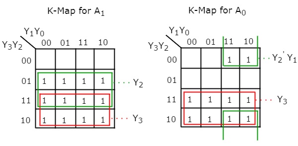
4 to 2 Line Encoder:
There are total of four inputs, i.e., Y0, Y1, Y2, and Y3, and two outputs, i.e., A0 and A1.

Truth Table:

Logical Expression of 4 to 2 line Encoder:
A1=Y3+Y2
A0=Y3+Y1
Logic Circuit:

- If input line "0010" and "0100" are active, the encoder will output "100", which represents the binary value of 4 (because "0100" has a higher value than "0010"). If more than one input line is active, the encoder will output the code corresponding to the highest-value input.
- In a 4 to 2 line encoder, each input line should represent a unique binary value. Therefore, if an input such as "0011" is applied to the 4 to 2 line encoder, it will not match any of the valid inputs, and the encoder will output "00", which represents an invalid or unused input condition.
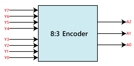
8 to 3 Line Encoder:
The 8 to 3 line Encoder is also known as Octal to Binary Encoder. In 8 to 3 line encoder, there is a total of eight inputs, i.e., Y0, Y1, Y2, Y3, Y4, Y5, Y6, and Y7 and three outputs, i.e., A0, A1, and A2.

Logical Expression:
A2=Y4+Y5+Y6+Y7
A1=Y2+Y3+Y6+Y7
A0=Y7+Y5+Y3+Y1
Logical circuit:

Priority Encoder:
In this priority encoder, there are total of 4 inputs, i.e., Y0, Y1, Y2, and Y3, and two outputs, i.e., A0 and A1. The Y3 has high and Y0 has low priority inputs.
Why
If more than one input signal is active at the same time, the priority encoder will prioritize the input signal with the highest priority and produce a code for that input signal.
Application: Priority encoders are commonly used in microprocessors and digital systems where multiple interrupt signals may be active at the same time, and the highest-priority interrupt needs to be serviced first.
Logical Expression:
A1=Y3+Y2
A0=Y3+Y2'.Y1
V=Y0+Y1+Y2+Y3
Truth Table:

Logic Circuit:

Difference between Normal encoder and One hot encoder:

Decoder:

What is a decoder?
The combinational circuit that changes the binary information into 2N output lines is known as Decoders.
Where is it used?
Decoders are used to convert an analogue signal into digital data, which can then be processed by a computer.
When is it used?
when we need to input data to a specific output line.
How does it work?
One of these outputs will be active High based on the combination of inputs present, when the decoder is enabled. That means the decoder detects a particular code.
Advantages of Decoder:
The advantage of a decoder is that it enables the efficient transmission, storage, and execution of digital data and instructions by allowing the original information to be retrieved from a compressed or encoded format.
Real time examples:
- Remote Control: When you press a button on a remote control, the signal is transmitted to the TV as a series of encoded pulses. The decoder in the TV then decodes these pulses to determine which button was pressed, and it responds accordingly.
- Security System: A security system may use a decoder to decode an encoded signal from a sensor or detector. The decoder then determines if the signal indicates a breach of security and triggers an alarm if necessary.
2 to 4 line Decoder:
In the 2 to 4 line decoder, there is a total of three inputs, i.e., A0, and A1 and E and four outputs, i.e., Y0, Y1, Y2, and Y3. For each combination of inputs, when the enable 'E' is set to 1, one of these four outputs will be 1.
Block Diagram :

Truth Table:

Logical Expression:
Y3=E.A1.A0
Y2=E.A1.A0'
Y1=E.A1'.A0
Y0=E.A1'.A0'
Logic Circuit:

3 to 8 line decoder:
The 3 to 8 line decoder is also known as Binary to Octal Decoder. In a 3 to 8 line decoder, there is a total of eight outputs, i.e., Y0, Y1, Y2, Y3, Y4, Y5, Y6, and Y7 and three outputs, i.e., A0, A1, and A2. This circuit has an enable input 'E'. when enable 'E' is set to 1, one of these four outputs will be 1.
How a 3 to 8 line decoder is known as binary to octal decoder ?
For example, if the inputs are A2 = 1, A1 = 0, and A0 = 1, output will be Y7 = 0, Y6 = 0, Y5 = 0, Y4 = 0, Y3 = 1, Y2 = 0, Y1 = 1, and Y0 = 0, which represents the octal number 12. So, in this example, the 3-bit binary input (A2, A1, A0) is being decoded into an 8-bit output (Y7, Y6, Y5, Y4, Y3, Y2, Y1, Y0) that represents an octal number.
Block Diagram:

Truth Table:

Logical Expression:
Y0=A0'.A1'.A2'
Y1=A0.A1'.A2'
Y2=A0'.A1.A2'
Y3=A0.A1.A2'
Y4=A0'.A1'.A2
Y5=A0.A1'.A2
Y6=A0'.A1.A2
Y7=A0.A1.A2
Logic Circuit:
