Latches without Enable - mbits-mirafra/digitalDesignCourse GitHub Wiki
Types of Latches
- SR Latch
- D Latch
- JK Latch
- T Latch
SR (Set-Reset) Latch
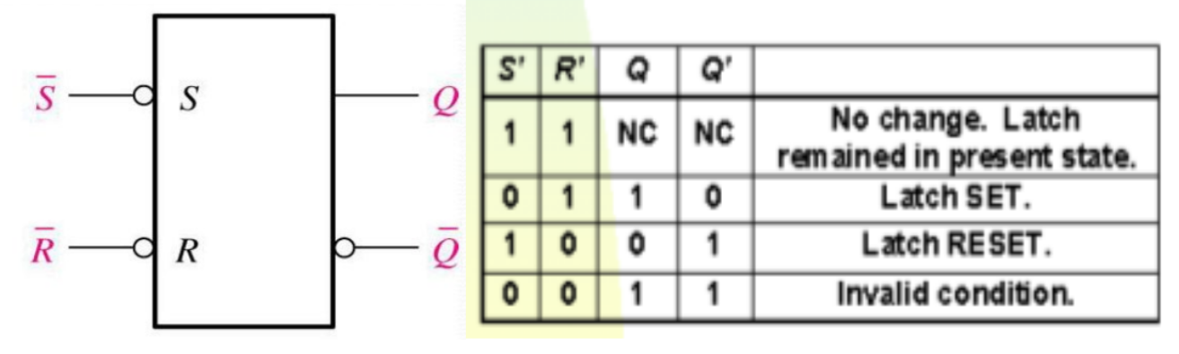
The SR latch is a sequential circuit which performs function of hold, set and reset. It depends on the S-states and R-inputs.
The SR latch design by connecting two NOR gates with a cross loop connection.
The SR latch can also be designed using the NAND gate. Below are the circuit diagram and the truth table of the SR latch.
Working
Case-1: S’=R’=1 (S=R=0)
If Q = 1, Q and R’ inputs for 2nd NAND gate are both 1.
If Q = 0, Q and R’ inputs for 2nd NAND gate are 0 and 1 respectively.
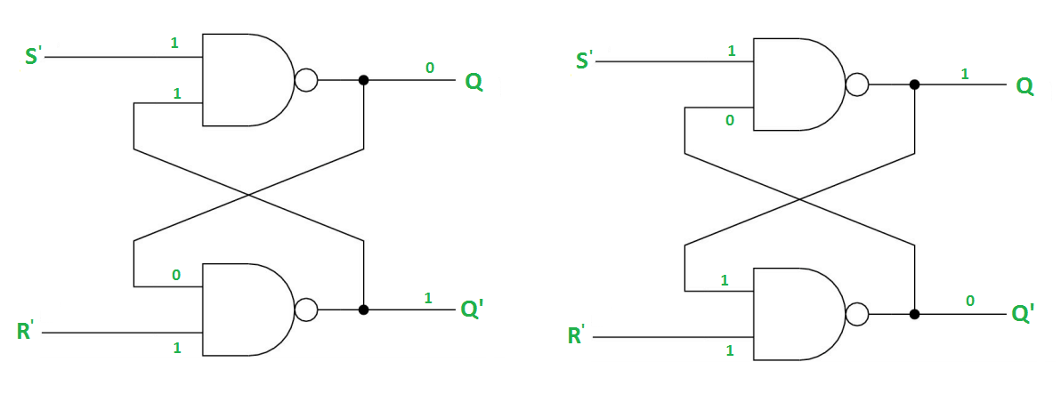
Case-2: S’=0, R’=1 (S=1, R=0)
As S’=0, the output of 1st NAND gate, Q = 1(SET state).
In the 2nd NAND gate, as Q and R’ inputs are 1, Q’=0.
Case-3: S’= 1, R’= 0 (S=0, R=1)
As R’=0, the output of 2nd NAND gate, Q’ = 1.
In the 1st NAND gate, as Q and S’ inputs are 1, Q=0(RESET state).
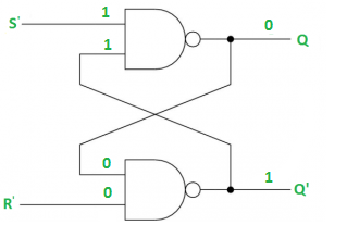
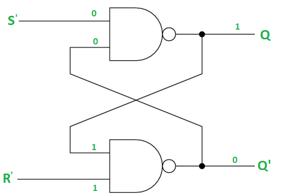
Case-4: S’= R’= 0 (S=R=1)
When S=R=1, both Q and Q’ becomes 1 which is not allowed. So, the input condition is prohibited.
D Latch
The problematic condition of the S-R latch is the de-assertion of S and R inputs at a similar timing. Such a condition of the indeterminant state is removed in D-latch. These circuits are constructed by using universal gates.
Block Diagram:
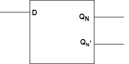
The implementation of this latch using NAND gates is
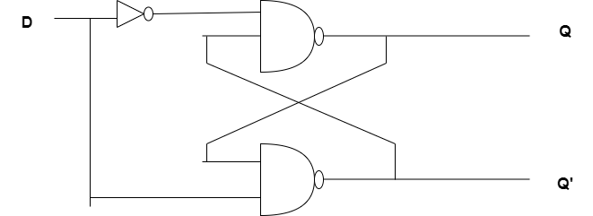
This type of latch doesn’t require any separate S or R inputs. This can be constructed by using single input ‘S’ and the other input R is obtained by connecting the inverter at the input. This single input can be referred to as D. The extension of the S-R latch is known as D-latch.
Truth Table of D-latch
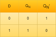
As the purpose of the S-R latch is to set or reset but the D-latches are capable of storing a single bit of information.
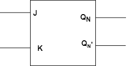
JK Latch
The Latches in which the output is fed back to the input is known as a J-K latch. The condition of the state under ambiguous has been eliminated in this circuit. When both the inputs J and K are HIGH the output states get toggled. It is similar to the basic S-R gate. The only difference is the feedback path application.
Block Diagram:
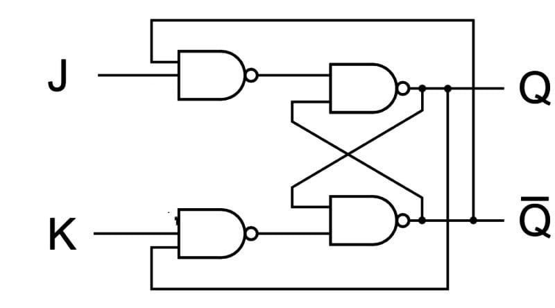
Circuit Diagram:
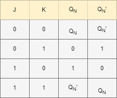
Truth table:
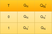
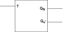
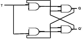
T Latch
The short-circuiting of the inputs of J-K latches are resulting in the formation of T-Latches. If the input applied is HIGH then the output states results inn Toggling.
Block diagram:
Circuit Diagram:
Truth table: