Flif Flop with Synchronous RESET - mbits-mirafra/digitalDesignCourse GitHub Wiki
Synchronous Reset
Synchronous reset is a technique used in digital circuits to reset the state of a circuit to a Zero, synchronized with a clock signal. In synchronous reset, a reset signal is applied to the circuit, but the circuit does not immediately change its state. Instead, the reset signal is synchronized with the clock signal, and the reset operation occurs only at the rising or falling edge of the clock signal.
Why we require it?
The advantage of using synchronous reset is that it avoids problems that can occur with asynchronous reset, where the reset signal can arrive at any time, leading to unpredictable behavior or glitches in the circuit. With synchronous reset, the reset signal is synchronized with the clock signal, ensuring that the reset operation occurs at a well-defined time and that the circuit behaves predictably. The synchronous reset ensures that the flip-flop is reset only when it is safe to do so, based on the timing of the clock signal. This can be particularly important in circuits with complex timing requirements, where resetting the flip-flop at the wrong time could cause errors or glitches in the circuit operation.
Example
D flip flop with synchronous reset ensures that the reset signal is recognised only at the positive edge of the clock signal, That is reset is synchronous with clock.
circuit diagram
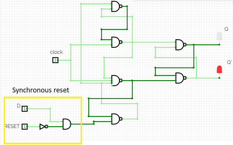
from the circuit diagram we can observe that we can implement synchronous reset for D flip flop by simply passing the input D and reset signal though AND gate , then giving output of AND gate as the input to the D flip flop. This arrangement ensures that whenever reset is 1 output of AND gate is 0 , since it is given as input to D flip flop the output of Flip flop will also be 0 at the positive edge and it remains 0 until reset becomes 0 during another positive edge.
Truth table
| CLK | D | R | Qn | Qn+1 |
|---|---|---|---|---|
| ↑ | X | 0 | Qn | D |
| ↑ | X | 1 | Qn | 0 |
Timing diagram
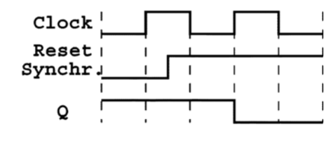
From the truth table and timing diagram we can observe that the output will be reset by reset signal only at the positive edge of the clock cycle, if reset signal is applied at other region except positive edge then flipflop will not respond to the reset signal