Asynchronous counters - mbits-mirafra/digitalDesignCourse GitHub Wiki
Binary Ripple Counter
What is Binary Ripple Counter?
Binary ripple carry counter is a specific type of ripple carry counter that counts in binary (base-2) and is commonly used in digital circuits and systems.
How Binary ripple counter works?
A binary ripple counter consists of a series of flip-flops, with the output of each flip-flop connected to the input of the next flip-flop. The first flip-flop, also known as the least significant bit (LSB), is connected directly to the clock signal, while the subsequent flip-flops are connected to the outputs of the previous flip-flops. When the clock signal transitions from low to high, the LSB flip-flop changes state and ripples through the subsequent flip-flops. The output of each flip-flop depends on the output of the previous flip-flop and the clock signal, creating a delay in the propagation of the count signal through the counter. The binary ripple carry counter can count up to a maximum binary value determined by the number of flip-flops used in the counter. For example, a four-bit binary ripple carry counter can count from 0000 (0) to 1111 (15) before resetting to 0000 again. There are two types of binary ripple counter.
1)Binary ripple up counter: A binary ripple up counter is a specific type of binary counter that counts up in binary (base-2) and is commonly used in digital circuits and systems. Here is the example for 4-bit ripple positive edge triggered up counter using T flip flop:
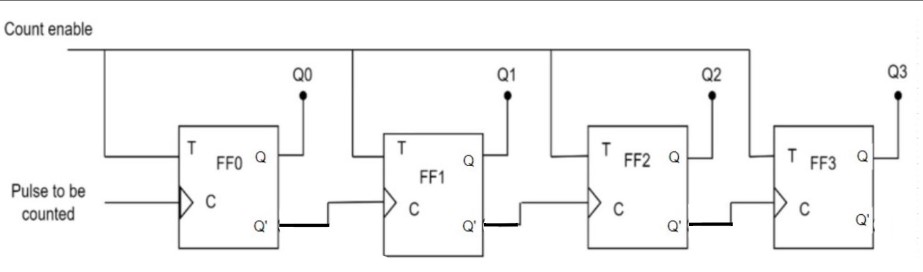
fig.1 Binary ripple up counter
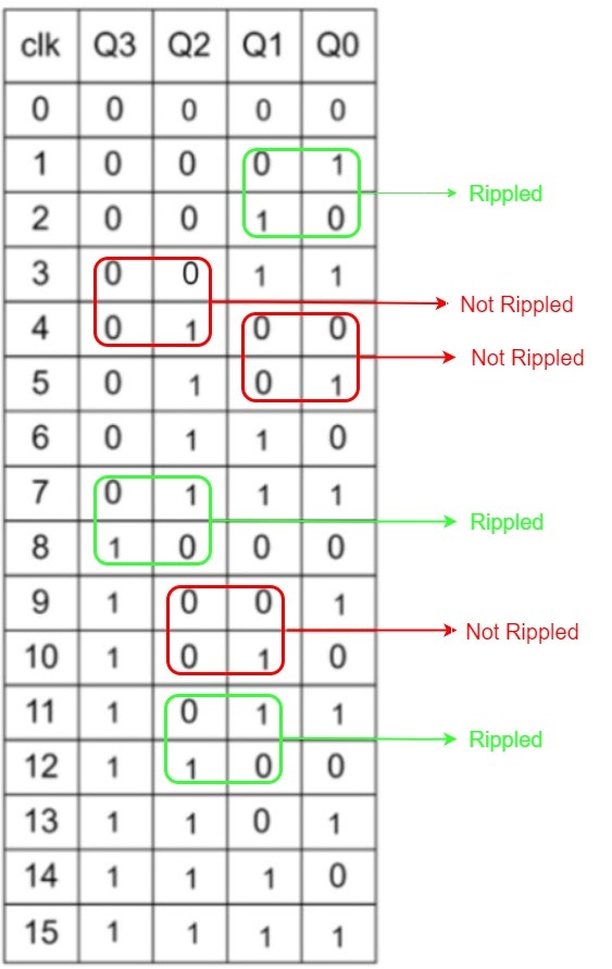
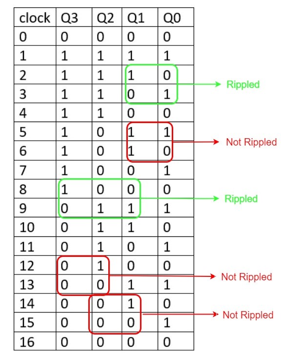
Truth table
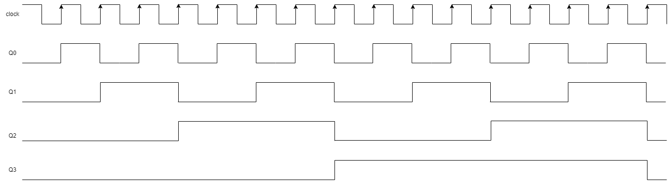
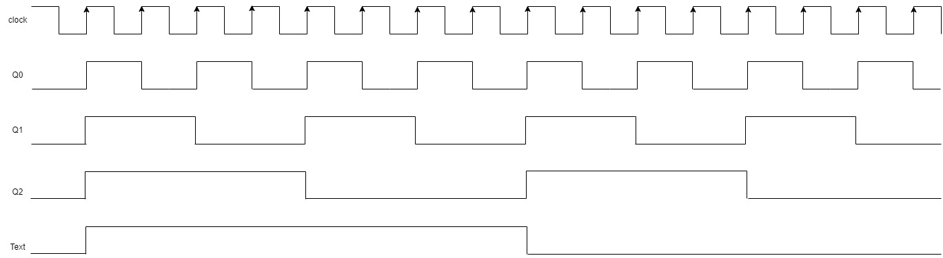
Timing diagram
Initially, all flip-flop inputs (T) are set to 0 (logic low) and all outputs (Q) are also 0. When a clock pulse is applied to the first flip-flop, it toggles its output from 0 to 1 (or vice versa) based on the value of its input T. Since the input of the first flip-flop is always 1 (due to the feedback connection), its output toggles with each clock pulse. When the first flip-flop's output changes from 0 to 1, it triggers the second flip-flop to toggle its output on the next clock pulse. This process continues down the line, with each flip-flop toggling on the rising edge of the clock signal only when its previous flip-flop output is high. The binary value represented by the outputs of the four flip-flops changes with each clock pulse. The counter starts at 0000 and counts up to 1111 before returning to 0000 and repeating the cycle. The time taken to count through all the binary values is equal to the number of clock pulses applied to the first flip-flop. In this case, it takes 16 clock pulses to count from 0000 to 1111 and reset back to 0000.
2)Binary ripple down counter: A binary ripple down counter is a specific type of binary counter that counts down in binary (base-2) and is commonly used in digital circuits and systems. Example of 4 bit ripple positive edge triggered down counter using T flipflop
block diagram:
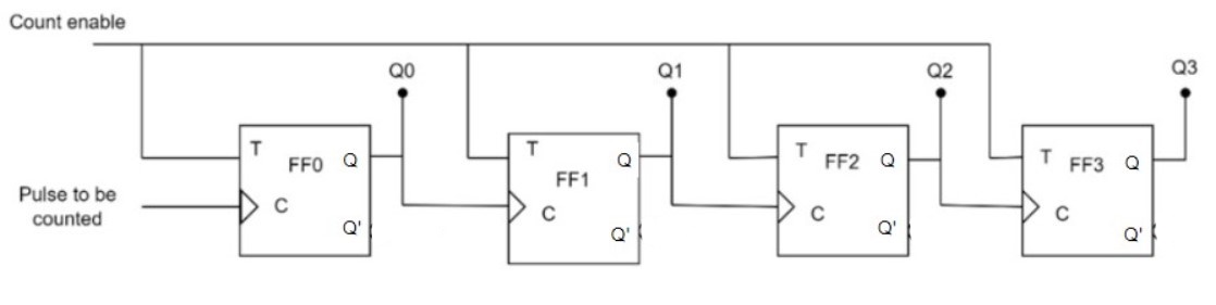
fig.2 Binary ripple down counter
Truth table
Timing diagram
Initially, all flip-flop inputs (T) are set to 0 (logic low). When a positive edge of the clock signal arrives, it triggers the first flip-flop to toggle its output from 1 to 0 (or vice versa) based on the value of its input T. The output of the first flip-flop changes only when the clock signal transitions from low to high (positive edge). When the first flip-flop's output changes from 1 to 0, it triggers the second flip-flop to toggle its output on the next positive edge of the clock signal. This process continues down the line, with each flip-flop toggling on the positive edge of the clock signal only when its previous flip-flop output is low. The binary value represented by the outputs of the four flip-flops changes with each positive edge of the clock signal. The counter starts at 1111 and counts down to 0000 before returning to 1111 and repeating the cycle. The time taken to count through all the binary values is equal to the number of positive edges of the clock signal applied to the first flip-flop. In this case, it takes 16 positive edges of the clock signal to count from 1111 to 0000 and reset back to 1111.
Why binary ripple counter?
Binary ripple counters are popular and widely used in digital electronics for several reasons, including Simplicity and ease of design, Scalability and Low power consumption.
Where binary ripple counter is used?
A binary ripple counter is a commonly used digital circuit because of its simplicity and ease of implementation. It is widely used in applications that require counting or sequencing, such as digital clocks and event counters. The binary ripple counter can be configured to count up or down. This allows it to be used in a variety of counting and sequencing applications.
Advantages:
Simplicity and ease of design: Binary ripple counters are relatively simple and easy to design, making them an attractive choice for many applications. They can be implemented using only basic logic gates and flip-flops, which are readily available and easy to integrate.
Scalability: Binary ripple counters can be easily scaled up or down in size to accommodate different counting ranges, making them versatile and flexible for a wide range of applications.
Disadvantages:
Propagation Delay: Binary ripple counters suffer from a significant propagation delay due to the sequential nature of the design. The output of each flip-flop depends on the output of the previous flip-flop. This delay can cause timing errors and limit the maximum clock frequency of the counter.
Limited Counting Range: Ripple counters are limited in their counting range by the number of flip-flops used in the design. For example, a 4-bit ripple counter can only count up to 15 in binary (1111), and then it resets to 0. To count higher values, additional flip-flops must be added, making the circuit more complex.