Adders - mbits-mirafra/digitalDesignCourse GitHub Wiki
ADDERS
WHAT IS AN ADDER:
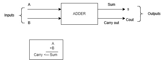
An Adder is a circuit that performs the binary addition of two numbers in Digital Electronics. It is a memoryless circuit(doesn't store any value) and performs an operation assigned to it logically by a Boolean expression. It is known as the fundamental block of arithmetic circuits in computers and other digital systems.
Here it usually takes two inputs and produces two outputs: sum, and carry. The sum bit is the result of adding two input bits and the carry bit indicates if there is any carry-over from the previous bit. The output depends upon the present input at any given time.
WHY TO USE AN ADDER:
Adders are widely used and highly optimized digital circuits for performing arithmetic addition and subtraction operations, and it is difficult to replace them with another circuit in most cases. While there are many types of digital circuits that can perform arithmetic operations, when it comes to addition and subtraction operations, adders are the most commonly used digital circuits. However, it's worth noting that these alternative circuits may not be as efficient or as widely used as adders for performing addition and subtraction operations. There are several reasons why adders are chosen over other digital devices:
-
Simplicity: Adders are relatively simple digital circuits that can be easily designed, implemented, and integrated with other digital circuits. They consist of basic logic gates like XOR, AND, and OR gates and do not require complex circuitry or control signals.
-
Versatility: Adders can be used to perform various arithmetic and logical operations, making them highly versatile building blocks. They can be used in different applications, ranging from simple calculators to complex microprocessors.
-
Speed: Adders are typically faster than other digital devices, such as microcontrollers or microprocessors, as they perform calculations in parallel. This makes them suitable for applications that require high-speed calculations, such as digital signal processing or cryptography.
-
Low Power Consumption: Adders typically consume less power than other digital devices, making them suitable for battery-powered applications.
WHERE IS AN ADDER USED:
In many computers and other kinds of processors, adders are used in the arithmetic logic units (ALUs). They are also used in other parts of the processor, where they are used to calculate addresses, table indices, increment and decrement operators and similar operations. Here are some real-time applications of an adder:
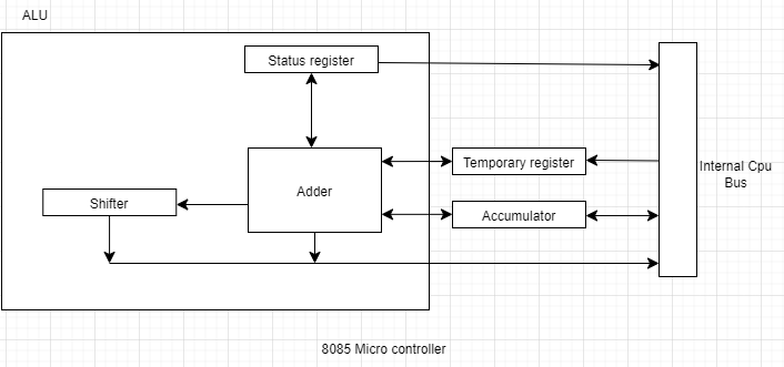
- Microprocessors and microcontrollers: Adders are used extensively in microprocessors and microcontrollers to perform arithmetic operations like addition, subtraction, and multiplication.
Adder in an 8085 Micro Controller.
- Digital Signal Processing: Adders are used in digital signal processing applications, such as filtering, compression, and modulation.
For example, in an audio application, adders are used to mix multiple audio signals.
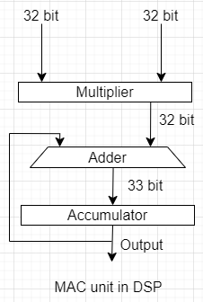
Also, a fundamental unit called MAC unit is used in DSP(digital signal processors) where to accumulate speed and performance in a processor.An adder is used in this MAC unit to achieve speed in a system.
- Image processing: Adders are used in image processing applications, such as edge detection, image enhancement, and feature extraction.
For example, in edge detection, adders are used to calculate the gradient of the image.
- Cryptography: Adders are used in encryption and decryption algorithms, such as the Advanced Encryption Standard (AES).
Adders are used to perform bitwise operations and add the results together to generate the final encrypted output.
- Computer graphics: Adders are used in computer graphics applications, such as rendering and shading.
For example, in rendering, adders are used to calculate the colour of a pixel based on the lighting conditions and the surface properties.
POSSIBLE OPERATIONS AN ADDER CAN BE USED FOR:
Here are some conditions where we can make use of adders:
- Arithmetic operations: If your application involves adding two or more numbers, you will need an adder.
For example, in a calculator or a computer program, adders are used to perform arithmetic operations like addition, subtraction, multiplication, and division.
- Precision: If your application requires high precision, you may need to use a specialized type of adder, such as a floating-point adder.
Floating-point adders are used in applications that require high precision, such as scientific simulations or financial modelling.
- Speed: If your application requires fast addition, you may need to use a specialized type of adder, such as a carry-lookahead adder or a carry-select adder.
These adders are designed to perform fast addition and are commonly used in high-speed applications like digital signal processing or image processing.
- Circuit complexity: If your application involves complex arithmetic operations, you may need to use a combination of adders and other digital circuits to implement the desired functionality.
In this case, you will need to carefully analyse the circuit complexity and optimize the design for performance, power consumption, and cost.
TYPES OF ADDERS:
Adders are classified into various types based on their design:
- half-adders,
- full-adders,
- ripple-carry adders,
- carry-lookahead adders,
- and carry-select adders.
These different types of adders have varying degrees of complexity, speed, and area requirements, and are suitable for different applications.
1. HALF-ADDER
A half adder is a digital circuit that performs the addition of two binary digits, producing a sum bit (S) and a carry bit (C) as outputs. It is called a "half adder" because it can only add "two single-digit binary numbers" (i.e., two bits(1,1)) and cannot handle any carry from a previous addition. A half adder typically consists of two inputs, labelled a and b, which represent the two binary digits being added, and two outputs, which are represented as the sum and carry bits, respectively. The output sum is the result of adding the two input bits without any carry. In comparison, output carry represents the carry that would be generated if the two input bits were added together along with a carry from a previous addition.

The truth table for a half-adder is as follows:
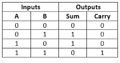
As you can see from the truth table, the output sum is the exclusive OR (XOR) of the two input bits, while the output carry is the logical AND of the same two bits. A half adder is a basic building block for more complex arithmetic circuits like full adders and multi-bit adders.
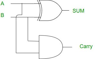
Half-adder using GATES:
K-Map for Sum and Carry of half adder:
- The equation determined for sum S= A⊕ B
- The equation determined for carrying C=A.B
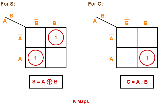
The empty spaces in the k-map represent '0' here.
Why and where a half adder is used:
WHY?
- Half adders are often used as building blocks for larger adders in digital circuits. In some cases, we may only need to add two single-bit numbers, such as when performing a Boolean operation, where we only need to know whether the inputs are both accurate or not. In this scenario, using another adder would be overkill and wasteful.
- When adding larger binary numbers, the least significant bits (LSBs) are typically added using half adders, while the more significant bits are added using full adders. This allows for the efficient implementation of larger adders while minimizing the number of components required.
- One such scenario is in low-power and low-cost embedded systems, where space and power consumption are critical factors. In such systems, using a simpler half-adder instead of another adder's can reduce the number of components and therefore the power consumption and cost of the system.
WHERE?
- An half adder may be preferred in certain digital signal processing (DSP) applications, where only small binary numbers need to be added or subtracted in real-time.
For example, in some audio processing applications, the input signals may be represented as small binary numbers, and only the LSBs of these numbers need to be added or subtracted. In such cases, using a half adder instead of a full adder can simplify the circuit and reduce latency, allowing for faster processing of the signals.
In summary, the choice between using a half adder or a full adder in real-time applications depends on the specific requirements of the application. While a full adder can add more bits, a half adder may be preferred in certain scenarios where simplicity, power consumption, or latency are important factors.
- In DSP, half adders can be used in circuits that perform bit-wise operations on digital data.
For example, in digital image processing, half adders can be used to perform bit-wise addition or subtraction of image pixels.
*Half adders can also be used in DSP applications to implement simple digital logic functions.
For example, they can be used to implement a comparator, which is a circuit that compares two digital signals and determines if one is greater than or equal to the other.}
Limitations:
It neglects the ‘carry’. Meaning if you add 1+1, it gives 0 and not 10 (which is the binary equivalent of 2) The carry bit generated from the previous bit cannot be added is the limitation of this adder. To perform addition for multiple bits these circuits cannot be preferred.
2.FULL-ADDER
A full adder is a digital circuit used in digital electronics and computing to perform the addition of binary numbers. It takes three inputs, two binary digits (representing the numbers to be added) a, b and a carry bit from a previous stage, and produces two outputs: sum and carry bit.

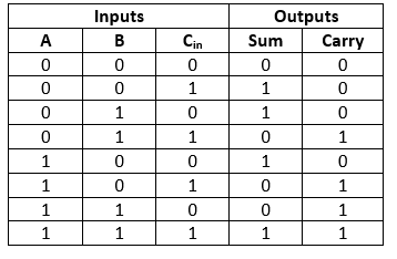
The inputs a and b are the two binary digits to be added, while Cin is the carry bit from the previous stage (which is 0 for the first stage). The outputs Sum and Cout are the sum of the two binary digits and the carryout bit, respectively. The truth table for a full adder is as follows:
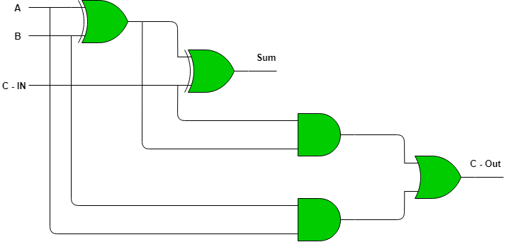
Full-adder using GATES:
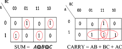
K-Map for sum and carry of full adder:
Half-adder circuits are used in computers, calculators, and various digital measuring instruments. Full adders are mainly used for multiple-bit addition, in digital processing devices, etc.
Why and where to use a full adder:
WHY?
Full adders and half adders are both types of adders used in digital circuits, but they have some differences in their capabilities and performance. Here are some reasons why a full adder may be preferred over a half adder in certain applications: The capability of Adding Three Inputs: Unlike a half adder that can only add two inputs, a full adder can add three inputs, including two binary numbers and a carry from the previous stage. This makes full adders more suitable for use in multi-bit arithmetic operations.
-
Higher Accuracy: Full adders produce more accurate results in binary addition because they take into account the carry bit generated from the previous stage, whereas half adders do not.
-
Better Performance in Overflow Situations: Full adders can handle overflow situations more efficiently than half adders. In an overflow situation, the result of the addition exceeds the maximum value that can be represented by the number of bits used in the addition. A full adder can detect and handle overflow situations by generating a carry-out signal, while a half adder cannot.
-
More Efficient Use of Logic Gates: Full adders use fewer logic gates than a combination of two half adders, making them more efficient in terms of space utilization and power consumption.
-
Faster Execution: Full adders are generally faster than a combination of two half adders, making them suitable for high-speed applications.
WHERE?
- Full adders are used in the key generation algorithms of symmetric-key cryptography. Symmetric-key cryptography, also known as secret-key cryptography, is a method of encryption where the same secret key is used for both encryption and decryption of the data. In this method, the key generation algorithm is used to generate the secret key.
Steps to generate a key:
- Generate random numbers: The first step in a key generation is to generate a set of random numbers. These random numbers are used to create the secret key.
- Apply mathematical operations: The next step is to apply a series of mathematical operations to the random numbers using full adders and other arithmetic circuits. These operations can include addition, subtraction, multiplication, and division.
- Full adders can be used in the implementation of parity functions. In error correction codes (ECC), a parity bit is an extra bit that is added to a binary code word to detect errors.
For example, a full adder can be used to implement a simple parity function called the exclusive OR (XOR) function. The XOR function returns a 1 if the inputs are different, and a 0 if they are the same. This function can be used to calculate the parity bit in an ECC.
However, it should be noted that full adders alone are not sufficient for error correction in digital systems(partially used because ECC(error correction codes) are more powerful).
- Full adders are used in DSP circuits to perform the addition and subtraction of digital signals.
For example, in digital audio processing, full adders can be used to perform sample-by-sample addition or subtraction of audio signals to create new audio effects, such as reverb, echo, or distortion.
Limitations:
Here are some limitations of full adders:
-
Complexity: Full adders are more complex than half adders, and they require more logic gates, which can increase the circuit's size and complexity.
-
Propagation Delay: Full adders have a propagation delay that can impact the speed of the digital circuit, especially in cascaded adder circuits where the carry output of one adder is connected to the carry input of the next adder. This delay can result in a time lag between the input and output signals.
The ripple carry adder has a delay in propagating the carry bit from the least significant bit to the most significant bit. This delay increases with the number of bits being added, which can make it slower than other adder designs.
-
Power Consumption: Full adders consume more power than half adders due to the additional logic gates required. In power-critical applications, this additional power consumption can be a significant drawback.
-
Limited Functionality: Full adders can only perform binary addition and cannot be used for other arithmetic or logical operations, such as subtraction or multiplication.
-
Limited Number of Bits: Full adders can only add binary numbers of a fixed number of bits, and the number of bits is determined by the number of inputs to the adder. This can be a limitation in applications where large numbers need to be added.