ASYNCHRONOUS INPUT T FLIP FLOP - mbits-mirafra/digitalDesignCourse GitHub Wiki
The T Flip-Flop is a sequential device with 2 inputs (T, CLK (clock signal)) and 2 outputs (Q and Q’). T is control input.
PR and CLR are asynchronous inputs or SET and RST are asynchronous inputs - that is the output responds to these input immediately. They are active low inputs.
SET sets the output to 1 and RST RESETS the output to 0.
Both SET and RST cannot be low at the same time - the output is undefined.
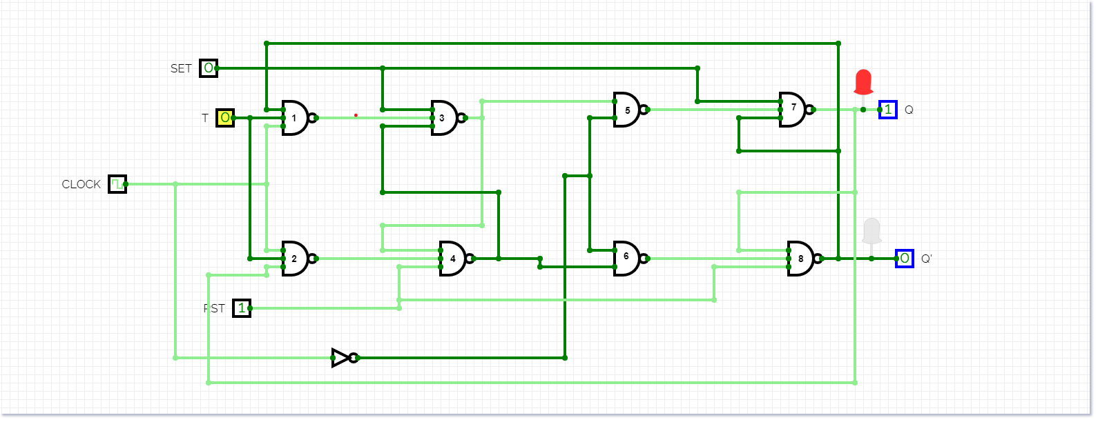
Circuit diagram
TRUTH TABLE:
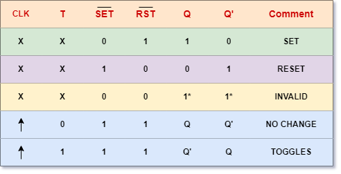
From the previous truth table it can be seen that the CLEAR (CLR) and PRESET inputs are active at a low logic level and put on the Q output of the Flip-Flop, a high logic level regardless of the state of the clock and / or the state of the T input. (see the T and clock inputs with an “X”).
In order for the T input and the clock to be functional, the SET and RESET inputs must be at a “High” logic level (not active), then:

If input T = 0, there is a memory or retention state (it keeps the output it had before the entries had changed). (Memory no change)

If input T = 1, the outputs Q and Q’ of the flip-flop change from a logical level to the opposite (“0” to “1” or “1” to “0”). (Toggle)
VIDEO: