Home - jean-michel-gonet/rc-to-dc-motor-controller GitHub Wiki
This is the journal I'm keeping while building this little project. I'm not writing it from top to bottom. Rather, I go up and down, refining my ideas as they become more mature. The point of having the journal is firstly to keep ideas clear in my messy head, because writing forces you to at least try to have a coherent discourse. It is also useful for future references to keep all drawings, parts id, photos and decision rationales in one place that wont disappear if I loose my computer.
Objectives
The main objective of this project is to radio control Meccano contraptions with 6V to 12V dc motors and standard stuff that you can buy in any RC model shop
Requirements
Meccano builders are used to 12V batteries and DC motors controlled with electromechanical relays. In contrast, RC model standards are 5V radio receptors and PWM controlled servos. In consequence, the requirements are the following:
- Functional:
- Use a standard radio control transmitter and receiver.
- Accept indefinite and extensible number of channels.
- Mixing DC motors and servos.
- Non - functional:
- 12V to 5V DC to DC 5A current conversion - required to power the radio control receiver plus several several servos. Meccano parts are made of metal and are quite heavy, so servos will be in heavy duty.
- DC motor can consume up to 10Amp.
- The custom modules are the only non-standard parts. Any other accessory has to be easily acquired in a radio control or Meccano shop.
Core idea
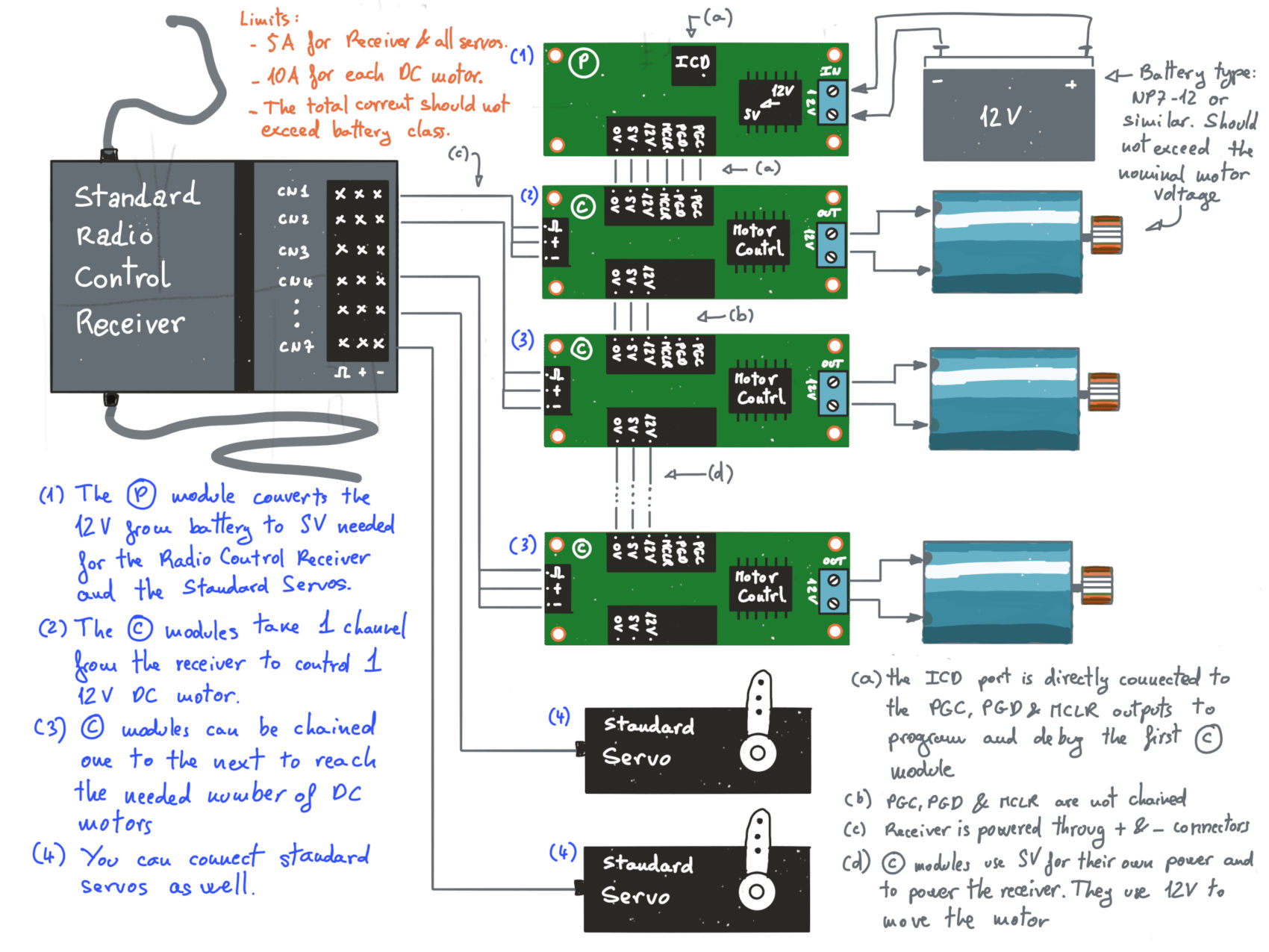
My first step in designing an electronic solution (or of any kind, actually) is to come up with the core idea, the 1 sheet sketch that for me represents what I'm trying to do:

Technical stack
I'm going to use the following technical stack:
- PIC from Microchip, because it happens to be the micro-controllers family I know best.
- Community edition of MPLabX from Microchip, because it is the logical consequence of using PIC microcontrollers.
- EasyEDA, because this is an open source project, and anyone can open an account there for free.
DC to DC converter with max16955 schematic
Using EasyEDA
By using EasyEDA I want to check two points:
- How it is to work with, given that it is a free tool. I'm comparing it with Proteus, which is my usual EDA.
- Is it doable, for a private, to order a small quantity of assembled circuits.
Until now I've always assembled circuits myself, but I'm using through-hole components. My circuits are big and heavy, not really suited to put onboard of plane and car models. I would like to make much smaller circuits with surface mount technology, but I'm afraid I won't enjoy the process. By using EasyEDA, I expect the assembly circuit to be easier to order, and consequently cheaper.
How is it to work with EasyEDA
Well, EasyEDA is incredibly good... to be a free tool. If you don't have any other tool, use it. It works very well, and does all the basics. Its interface has some non-intuitive traps, but all EDA have those. It is totally possible to work with to draw the schematic and the PCB. And, if you're stuck somewhere, you can use the forum. The company pays guys to answer questions there, so you will be helped in a day or less.
About simulation... well, EasyEDA does simulate. It is not its strongest suit, but it works.
Prototyping
I've prototyped each module separately:
668642
Initial notes:
- Use BJT for small driver transistors. Here's why: https://oscarliang.com/bjt-vs-mosfet/
- Possible MOSFET, if you dare to use SSC - 100A, 1.4V, 750µΩ rds, 1.16CHF:
- A cheap motor: https://ch.farnell.com/fr-CH/multicomp/mm28/moteur-miniature-2-4-4-5v/dp/599128