P Module prototype - jean-michel-gonet/rc-to-dc-motor-controller GitHub Wiki
The only task for the (P) module is to convert 12V DC into 5V DC (oh, and, say, would it be possible to work also with 6V?). This is called a step down dc to dc converter, and there are thousands of them in the internet. Why building one, then? Because we need a converter that is Meccano standard on one side, and radio control standard on the other side.
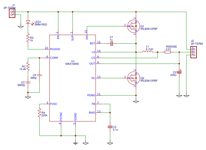
So, custom converter it is. Still, we can use a power switching regulator like the MAX16955 to simplify our design:

Calculations
The inductance
To calculate the value of the inductance, I used this online switching converter calculator with the following specifications:
- Input voltage: 12V
- Output voltage: 5V
- Output current: 10A (yes, that's double than our specification, but this is only a prototype).
- Frequency: 200kHz (it is the working frequency of the MAX16955)
- Output voltage ripple: 2%
- Inductor Current Ripple: 30% (from MAX16955 specification, page 16 - A good compromise between size and loss is a 30% peak-to-peak ripple current to average-current ratio).
The calculator returns an Inductance value of 4.2µH
The Rsense
In page 17, the specification instructs to Dimension Rsense so the maximum current (10A) induces a voltage of 72mV across Rsense. That would be R = 72*10^-3 / 10 = 0.0072Ω. Power consumption will be of maximum 10A * 72mV = 0.72W.
Bootstrap capacitor
- Bootstrapping capacitor: In page 21, Ideally the bootstrap capacitance should be at least nine times the gate capacitance. Well, then I need to choose a MOSFET N first.
Choice of components
My initial choice of components was the following (all at Farnell, which is an Element-14 electronic components web shop):
- Inductance: https://ch.farnell.com/fr-CH/wurth-elektronik/744750530047/inductance-4-7uh-11-8a-20-radial/dp/2493151
- Rsense: My usual provider has no traversing resistor between 0.005Ω and 0.01Ω, so I choose the latter. It will limit my current at 7.2A, but this is still plenty (our requirement was 5A) - https://ch.farnell.com/fr-CH/international-resistive/lob1-r010-flf/current-sense-resistor-0-01-ohm/dp/1499404
- MOSFET: In low voltage applications, Rdson resistance is the primordial characteristic of the transistors. In prototyping I prefer traversing devices, so I settle for IRLB3813PBF because of its 0.001Ω (10 times less than the Rsense!): https://ch.farnell.com/fr-CH/infineon/irlb3813pbf/mosfet-n-ch-30v-190a-to220/dp/1740786
- Bootstrap capacitor: The gate charge of the IRLB4813 is 86nC. The bootstrap capacitor should be 10x as big, so its value should be in the region of 1µC.
- Bootstrap diode: Any small signal Schottky diode would do, for example the BAT48 - https://ch.farnell.com/fr-CH/stmicroelectronics/bat48/diode-schottky-petits-signaux/dp/9801472
Compensation design (more calculations)
MAX16955 measures an error voltage, which is the difference between the output voltage and the required voltage (configured through, when 0 then required voltage is 5V). The error circuit adjusts the PWM ratio to keep the error voltage as close to 0 as possible, even as the the load is modifying its consumption.
In our case, the load is going to be the radio control receptor, whose consumption is very stable, and an undetermined number of servos, whose consumption can instantly jump from 0A to 1A, depending on the ongoing maneuver.
As any feedback system, the error circuit is subject to oscillation in some conditions. The compensation circuit is helping MAX16955 to oscillate.
To size the components of the compensation circuit I follow the insane procedure from page 19 of MAX16955:
- Initial calculations: GAINmoddc ≈ gmc * Rload;
- gmc = 1 / (Avcs * Rdc)
- Rdc is the DC-resistance of the inductor or the current-sense resistor in Ω: Rsense = 0.01Ω
- Avcs is the voltage gain of the current-sense amplifier and is typically 11V/V
- So: gmc = 1 / (11 * 0.01) = 9.09
- Vload = 5V, Iload = 10A, Rload * Iload = Vload ==> Rload = 0.5Ω
- Finally: GAINmoddc = 4.55
- Fpmod:
- Fpmod = 1 / (2*pi * Cout * Rload)
- Cout = 220µF
- Rload we calculated before as 0.5Ω
- Therefore: Fpmod = 1446 Hz
- Fc:
- The loop-gain crossover frequency (fC) should be set below 1/5 the switching frequency and much higher than Fpmod:
- Fc = 200kHz / 5 = 50kHz.
- 50Khz is 30x higher than Fpmod.
- Fzmod:
- Fzmod = 1 / (2*pi * esr * Cout)
- ESR (Equivalent series resistance of the capacitor):
- Choosing a capacitor: https://ch.farnell.com/fr-CH/rubycon/50zl220mefc10x16/condensateur-220-f-50v-20/dp/1144714
- According to datasheet: ESR = 0.042Ω
- Fzmod = 17225 Hz
- Therefore: Fzmod < Fc
- So:
- Rc = Vout * Fc / (gmea * Vfb * GAINmodfc * fzmod)
- gmea = 2500µs
- GAINmodfc = GAINmoddc * (Fpmod / Fzmod)
- GAINmodfc = 4.55 * (1446 / 17225) = 0.38
- Vfb = 1V typical
- Rc = 5 * 5010^3 / (250010^-6 * 1 * 0.38 * 17225) = 15.2kΩ
- Cc = 1 / (2pi * Fpmod * Rc) = 1 / (2pi * 1446 * 15.2*10^3) = 7.2nF
- Cf = 1 / (2pi * Fzmod * Rc) = 1 / (2pi * 17225 * 15.2*10^3) = 607pF
I would be extremely worried of the above calculations because I have no real understanding of them. Fortunately, Maxim provides an Evaluation Kit for the MAX16955, and the public datasheet shows the schematics in page 4. The Rc and Cc values are very close to my own results, and I'm going to trust myself for the optional Cf.
Connectors
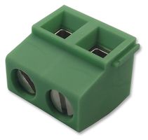
Meccano builders seem to be fond of those green screw terminals. Their technical name is PCB terminal block, Wave soldering, Screw connection with tension sleeve:

- 2 poles: https://ch.farnell.com/phoenix-contact/1729128/bornier-sur-ci-2v-5-08mm/dp/3041440
- 3 poles: https://ch.farnell.com/camdenboss/ctbp0508-3/bornier-fil-a-carte-3-voies-16awg/dp/2668642
TSSOP16 package
For my prototype I'm using a perfboard with 2.54mm grid, but MAX16955 is only available in TSSOP16 package:
- This is my first attempt at SMB. I'm following this method: https://jeelabs.org/book/1513c/
- TSSOP16 to DIP16 adapter: https://ch.farnell.com/fr-CH/aries/lcqt-tssop16/adaptateur-ci-16-tssop-dip-2-54mm/dp/2476038
- Extra fine soldering tip: https://ch.farnell.com/ersa/0102pdlf02-sb/panne-conique-0-2mm/dp/1203966
- Bent tweezers (what is the difference between cheap and expensive ones?): https://ch.farnell.com/fr-CH/duratool/1pk-104t-f/pince-brucelle/dp/3127588
- Soldering flux: https://www.conrad.ch/fr/stylo-a-flux-de-brasage-stannol-x33s-07i-conditionnement-10-ml-f-sw-23-2509032.html
In the end, I preferred this method: https://youtu.be/PUFCDh9BxQU, using the default normal 2mm tip that comes with the ERSA i-con nano.
Prototype of (P) Module
I'm just implementing the typical application proposed in page 1 of the MAX16955 datasheet.
- I need to create a new component for the MAX16955, as I can't find it in the libraries.

This is my BOM:
| Ref | Q. | Manuf. Reference | Price (CHF) | Cost (CHF) |
|---|---|---|---|---|
| Q1, Q2 | 2 | IRLB3813PBF | 1,540 | 3,080 |
| C1 | 1 | MCMLR50V105KX7R | 0,606 | 0,606 |
| L1 | 1 | 744750530047 | 2,600 | 2,600 |
| RSENSE | 1 | LOB1 R010 FLF | 1,570 | 1,570 |
| C2 | 1 | 50ZL220MEFC10X16 | 0,653 | 0,653 |
| J1 | 1 | 1729128 | 0,663 | 0,663 |
| J2 | 1 | CTBP0508/3 | 0,808 | 0,808 |
| C3 | 1 | K104K20X7RH5TH5 | 0,268 | 0,268 |
| RC | 1 | MCMF0W4DF1542A50 | 0,139 | 0,139 |
| CC | 1 | C315C682K1R5TA7303 | 0,497 | 0,497 |
| CF | 1 | SR211A681JAR | 0,480 | 0,480 |
| LED1 | 1 | 521-9215F | 1,430 | 1,430 |
| R3 | 1 | MCF 0.5W 1K | 0,040 | 0,040 |
| U1 | 1 | MAX16955AUE/V+ | 6,090 | 6,090 |
| 1 | LCQT-TSSOP16 | 7,520 | 7,520 | |
| R4 | 1 | MF25 220K | 0,040 | 0,040 |
| Total Cost | 26,485 |