11. Equipment - gordtulloch/Galileo GitHub Wiki
11. Equipment
Overview. Every control on this screen has detailed built-in help: hover it, press F1, or click the ? beside the title. See Built-in Help.
The Equipment section is where you connect, configure and save every device attached to a Pier. It has one screen per device category; all screens follow the same pattern.
Contents
- How equipment screens work
- Camera
- Mount
- Filter Wheel
- Focuser
- Rotator
- Optics
- Switches
- Flat Panel
- Weather and Safety Monitor
- Dome
- Aux
- Auto-connect
How equipment screens work
Every device screen has the same three-field connection row at the top:
| Field | Meaning |
|---|---|
| Driver | Alpaca (ASCOM network protocol) or INDI (Linux/macOS/Pi server) |
| Server | Host name or IP address of the machine running the device or indiserver. Use localhost if it is the same machine. .local mDNS names work, including on Windows. |
| Port | Default is 32323 for Alpaca (the common Seestar / ASCOM Remote default) or 7624 for INDI. Change this to match whatever your device documents. |
Workflow:
- Fill in Driver, Server and Port.
- Click Scan. Galileo queries the server and lists found devices in the log pane at the bottom and in each device's Device drop-down.
- Pick your device from the Device drop-down.
- Click Save to store the settings under the selected Pier.
Settings are always stored per Pier. Make sure the correct Pier is selected in the top bar before saving.
Camera
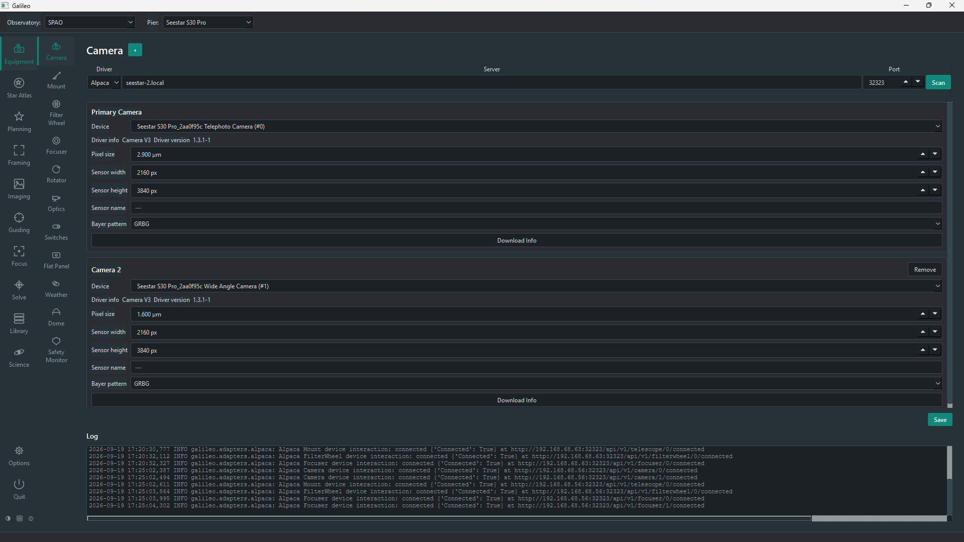
After scanning and picking your camera from the Device drop-down:
| Setting | Meaning |
|---|---|
| Download Info | Reads pixel size and sensor dimensions from the camera over the protocol and fills them in automatically. |
| Pixel size (µm) | Sensor pixel size; used for plate-solve pixel-scale calculations and FOV overlays in Star Atlas. |
| Sensor width / height (px) | Used for FOV calculations. |
| Bayer pattern | For one-shot-colour (OSC) cameras: RGGB, BGGR, GRBG, GBRG. Sets the debayer pattern used in the preview. |
| Sensor name | The sensor model, if the driver reports it. |
| Max well depth (e-) | The sensor's full-well capacity, from its datasheet; the Flats Assistant uses it to work out flat exposures. |
| + button | Add a second camera on the same connection (for Piers with multiple cameras on one Pier). Extra cameras share the Driver/Server/Port row but are separate devices. |
Mount
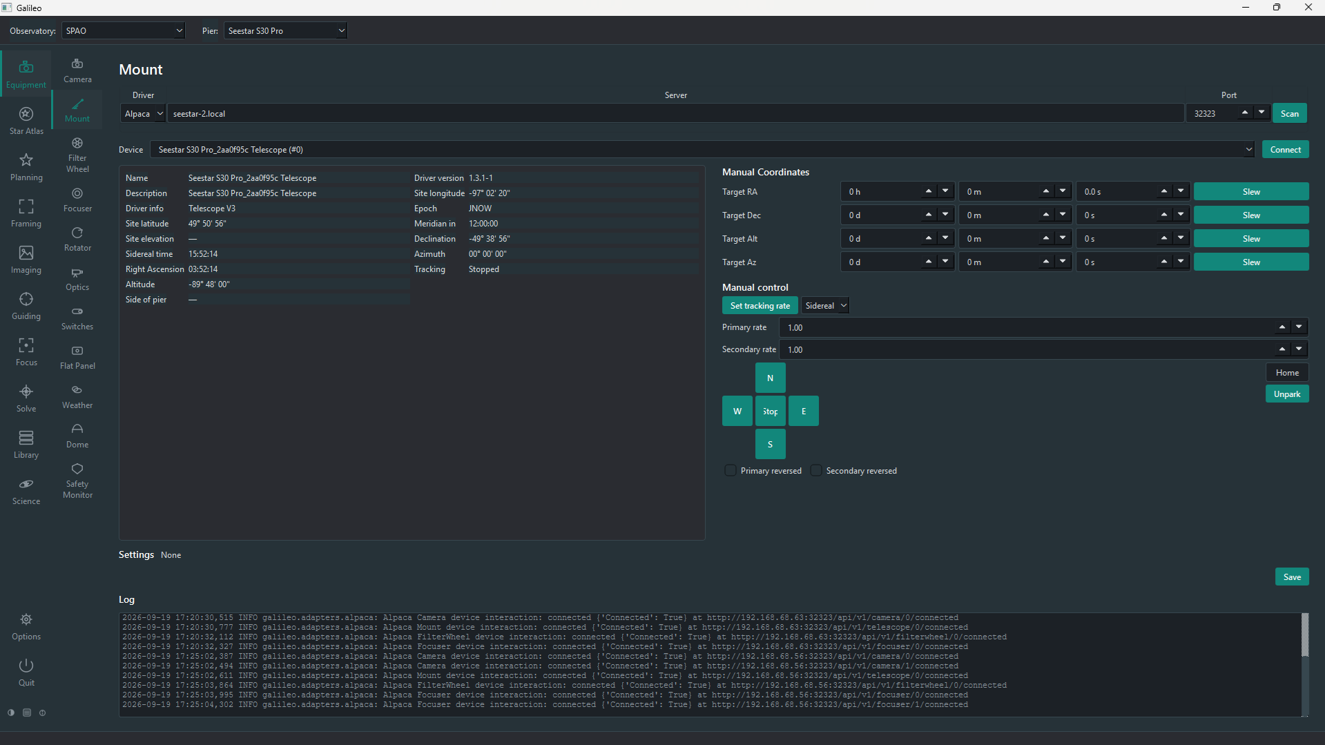
After connecting, the Mount page shows live status and manual controls:
| Status field | Meaning |
|---|---|
| RA / Dec | Current pointing position in J2000 equatorial coordinates |
| Altitude / Azimuth | Current pointing in horizontal coordinates |
| Sidereal time | Local sidereal time |
| Time to meridian | How long until the target crosses the meridian (positive = not yet, negative = past) |
| Pier side | East or West |
| Tracking | Whether tracking is on; the tracking rate (sidereal, lunar, solar) |
| Parked | Whether the mount is currently parked |
Manual controls:
| Control | Effect |
|---|---|
| Slew to RA/Dec or Alt/Az | Type coordinates and press Slew; tracking starts when the slew ends |
| Tracking On / Off, tracking rate | Start or stop tracking, and choose Sidereal, Lunar, Solar or King rate |
| N / S / E / W pad and Rate | Jog at Fine, Medium or Coarse speed until you press Stop; Primary/Secondary reversed flip the directions |
| Park / Unpark / Home | Park the mount, release it, or send it home |
| Stop | Halt any slew or jog immediately |
Meridian flip and limits. The page also holds the mount's safety settings, saved per Pier. Flip if HA > makes Galileo flip a tracking mount to the other side of the pier once it is a set number of degrees past the meridian. Limits stop the mount, and refuse slews, outside a minimum/maximum altitude or beyond a maximum hour angle. They apply wherever the slew was asked for, including sequences.
Filter Wheel
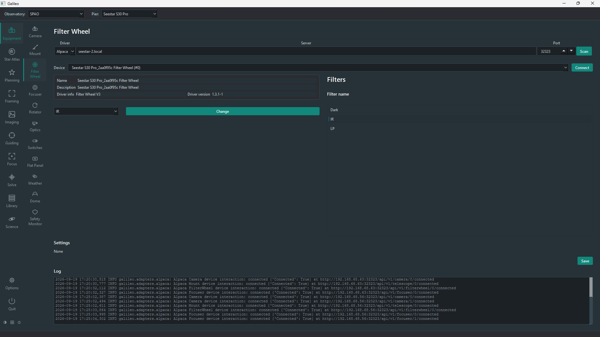
After connecting, the Filter Wheel page shows the wheel's name and description, the filter currently in place, and the list of filter names read from the wheel. Choose a filter in the box and press Change to move the wheel. Filter names come from the wheel's own configuration (the ASCOM driver or INDI properties); they appear in the Imaging screen's Filter drop-down, in session blocks and in Library metadata. Focus offsets per filter are measured on the Focus screen.
Focuser
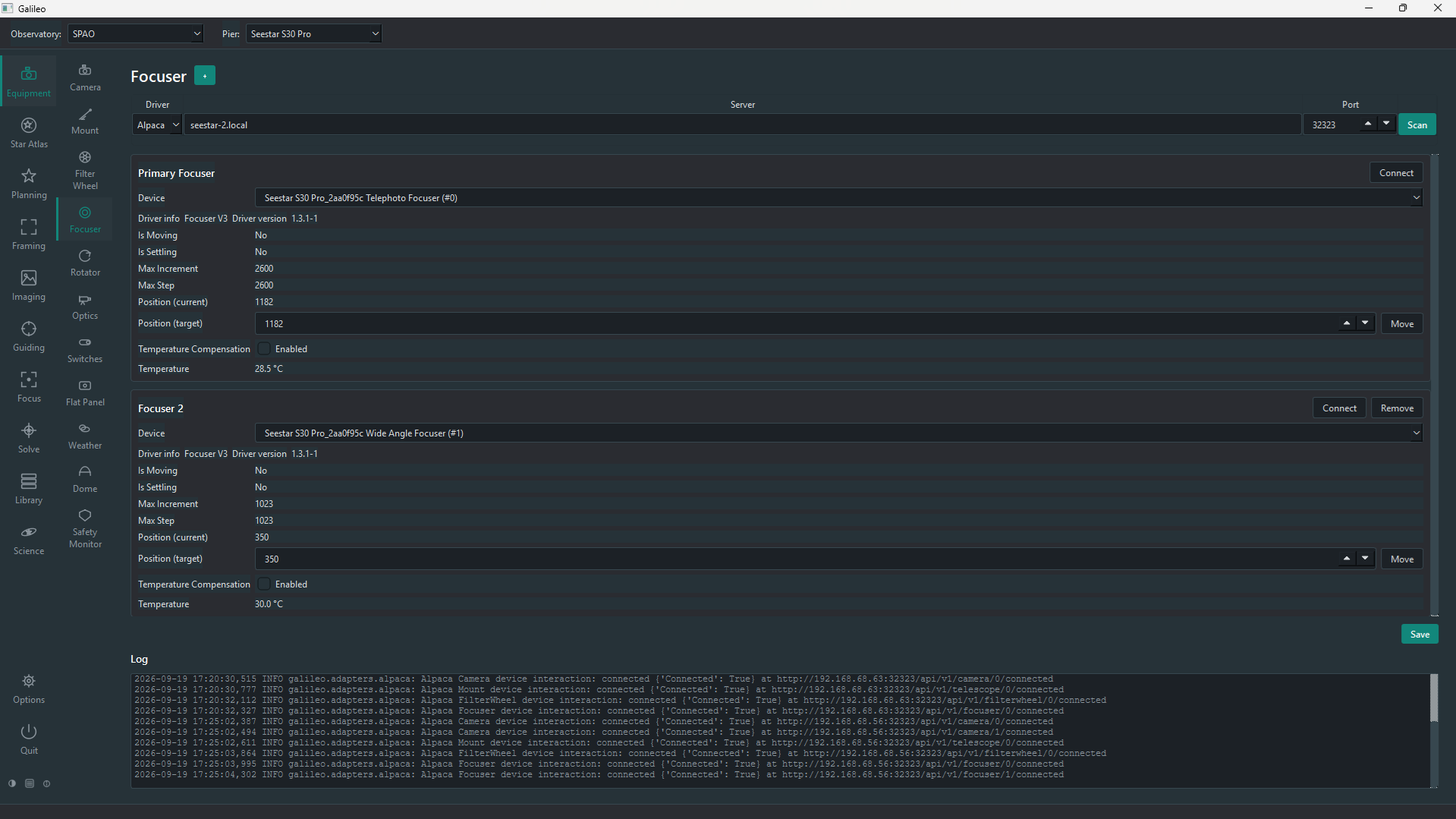
After connecting, the Focuser page shows live status — whether it is moving or settling, its current position, its range (Max Step, Max Increment) and its temperature. Type a Position (target) and press Move. Temperature Compensation turns the focuser's own compensation on or off, if the device has it. A telescope with more than one focuser gets extra panels with +. Autofocus itself is on the Focus screen.
Rotator
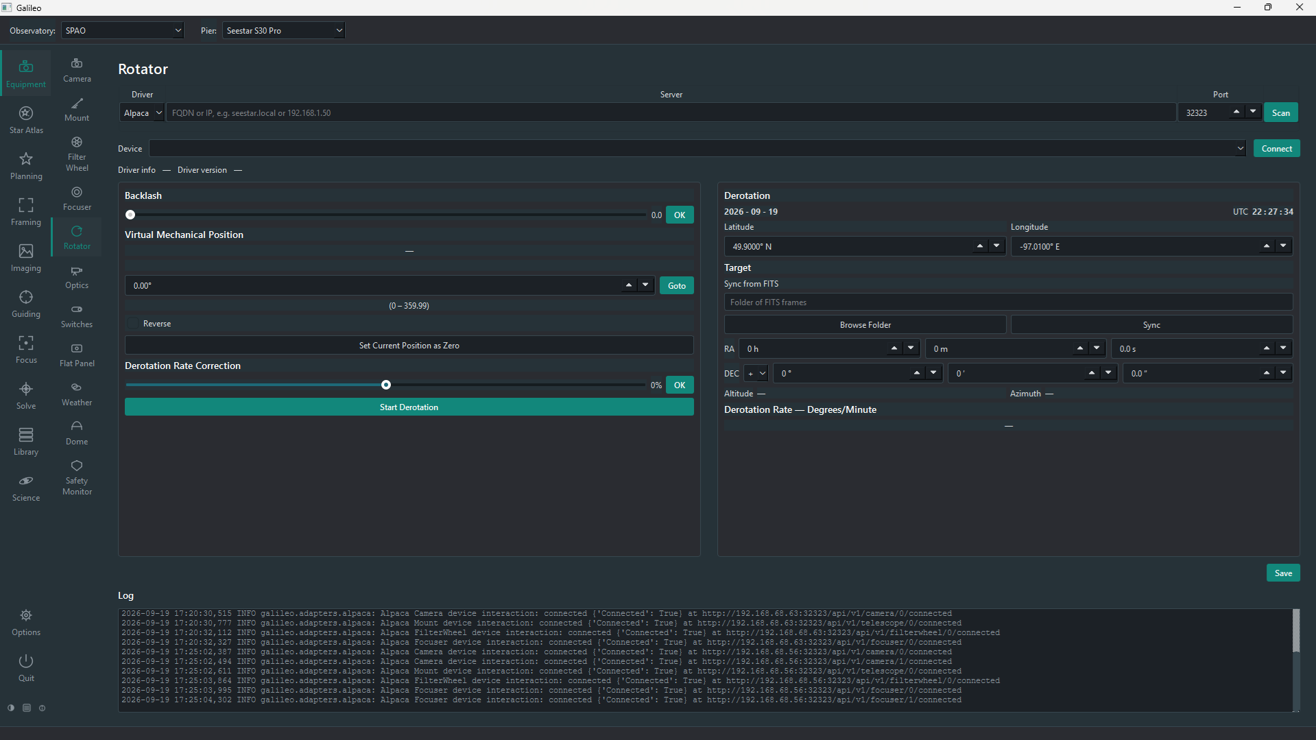
The Rotator page shows the current position and lets you turn the camera: type an angle and press Goto, set the current position as zero, reverse the direction, and set backlash. It can also derotate continuously: on an alt-azimuth mount the sky field rotates as the target moves, and the rotator cancels that turn, using the site's latitude/longitude and the target's coordinates (typed in or synced from a FITS file). A trim of ±100% fine-tunes the rate.
Optics
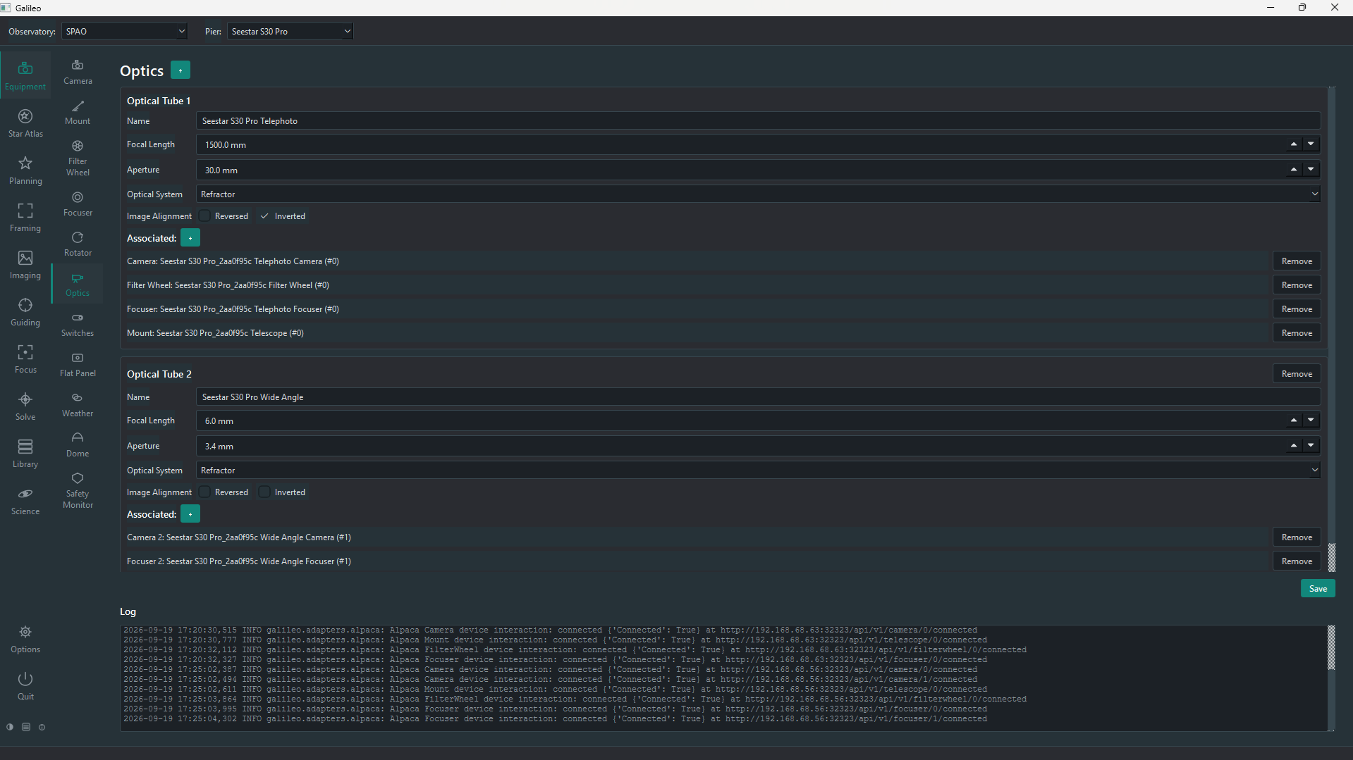
The Optics page ties devices together into optical tubes — each tube is one telescope. A Pier can have more than one optical tube (e.g. a main scope and a guide scope on the same mount).
Creating an optical tube
- Click + next to "Optical Tubes" to add a new tube.
- Fill in the tube's details:
| Field | Meaning |
|---|---|
| Name | A friendly label, e.g. "Esprit 150" or "Main scope". Appears in the top bar's Optics selector. |
| Focal length (mm) | Used for FOV overlays, plate-solve pixel-scale checking, and the top bar label. |
| Aperture (mm) | Used to compute the focal ratio for the top bar label. |
| Optical design | Refractor, Newtonian, Schmidt-Cassegrain, etc. Informational only. |
-
Click + next to Associated to attach devices to this tube. Only devices already saved on their own Equipment pages appear in the list. Associate a camera, filter wheel, focuser and/or rotator.
-
Click Save.
The Imaging, Focus and Solve screens use the optics selected in the top bar's Optics selector to know which camera, filter wheel and focuser to talk to.
Switches
The Switches page connects to an INDI or Alpaca switch device (power distribution units, relay boards, etc.). After scanning and saving, the page shows each switch as a toggle. Use switches to power devices on and off without leaving Galileo.
Flat Panel
The Flat Panel page controls a light panel for flat frames: a motorised dust cover with a built-in light (a Flip-Flat), or a fixed observatory panel. It shows the cover and light state, Park/Unpark for the cover, Light On/Off and a Brightness setting. The Flats Assistant and session Flat Capture blocks use it automatically when the Flat Panel method is chosen.
Weather and Safety Monitor
The Safety page connects the devices that tell Galileo whether it is safe to image: a weather station (temperature, humidity, wind, cloud, rain…) and/or a safety monitor that simply reports safe or unsafe. Several can be added, each on its own tab. For each measure you choose whether it counts and the value at which it becomes unsafe; a banner shows SAFE or UNSAFE with the reasons. When conditions are unsafe, sessions stop imaging and close up, and the dome will not be opened.
Dome
The Dome page controls a dome or roll-off roof: Open and Close the shutter, Park, and Abort, with the shutter state and azimuth shown. An Observatory Status box summarises the dome and the weather and says whether the observatory is Ready.
Aux
The Aux page controls any other device that has no page of its own — dew heaters, power boxes, lens covers. Once an INDI or Alpaca Switch device is connected, Galileo builds the panel from whatever switches, numbers and text fields the driver offers, grouped as the driver groups them.
Auto-connect
Saved cameras and focusers connect automatically when a Pier is selected in the top bar, and again when Galileo starts up. Other devices (mount, filter wheel, rotator, etc.) have a manual Connect button because some setups prefer to connect them only when needed. If auto-connect fails, the log pane on the device's page shows the reason.