Tutorial Create Webots Robot - cyberbotics/webots_ros2 GitHub Wiki
This tutorial will teach you how to create a custom robot in Webots.
In case you want to use a URDF or Xacro file check these tutorials.
NOTE: This tutorial has been made in the version R2022a of Webots with axis
Zup. With older versions the positions, rotations and axis for the motors will not be the same.
A tutorial on how to create a custom Webots - ROS 2 package using this robot can be found on the official ROS 2 documentation.
Before creating a robot you will create the environment in which your robot will evolve. First, launch Webots.
Once it is open, click on File > New World.
A new empty world will be created.
Now you will add some light, a background and an arena.
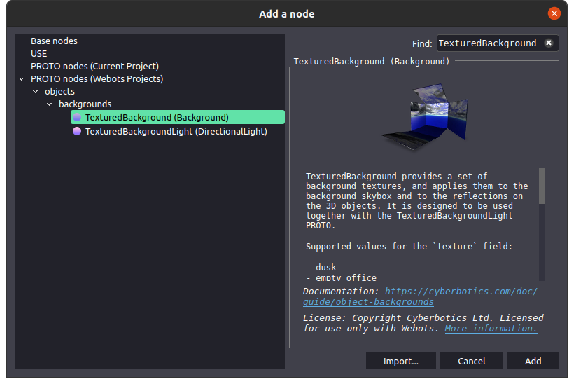
Press Ctrl+Shift+A to add an object or press the Add button (the second button of the top toolbar, the + icon).
Then use the search bar, type TexturedBackground, click on the corresponding object and then press the Add button.
Repeat the process to add a TexturedBackgroundLight node and a CircleArena node in order to obtain the same setup than in the following image.
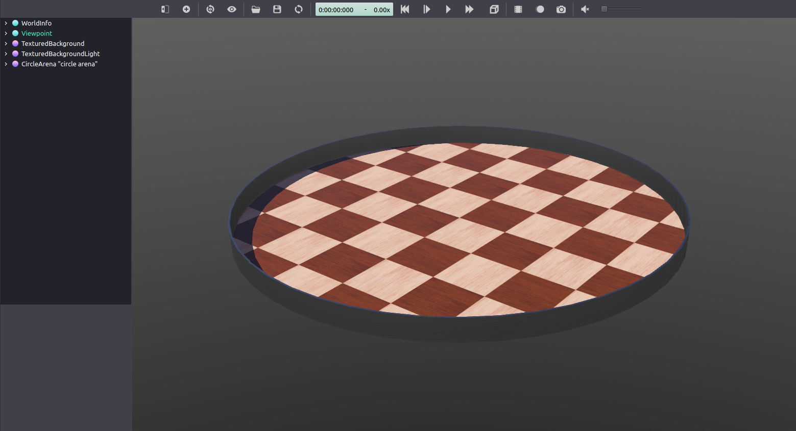
You can now navigate into your world with the right click of the mouse and rotate the point of view with the left click.
Go to File > Save World As ..., and save your file at the desired location.
Your world environment is ready and it is time to create your robot! You will start gently with a robot composed of a cylindrical body and two wheels.
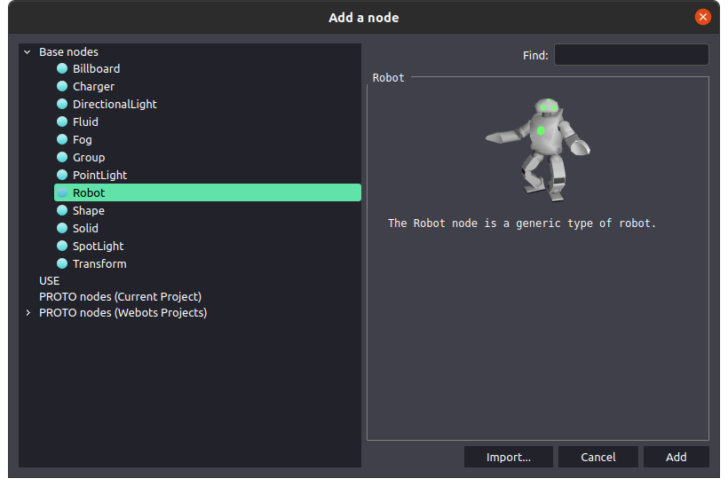
Start by adding a Robot object.
Press the Add button, open Base nodes (double click or press the arrow button) and then click on Robot > Add.
In the scene tree (on the left), expand the Robot pan.
You will now add the components of the robot.
Click on children > Ctrl+Shift+A > Base nodes > Transform > Add to add a Transform node.
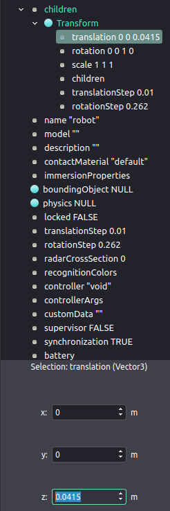
Then expand the new created node (the Transform node) and set the translation to 0 0 0.0415 in order to elevate a bit your robot.
Add a Shape node to children of the Transform node.
Expand the Shape node, select geometry and add a Cylinder node.
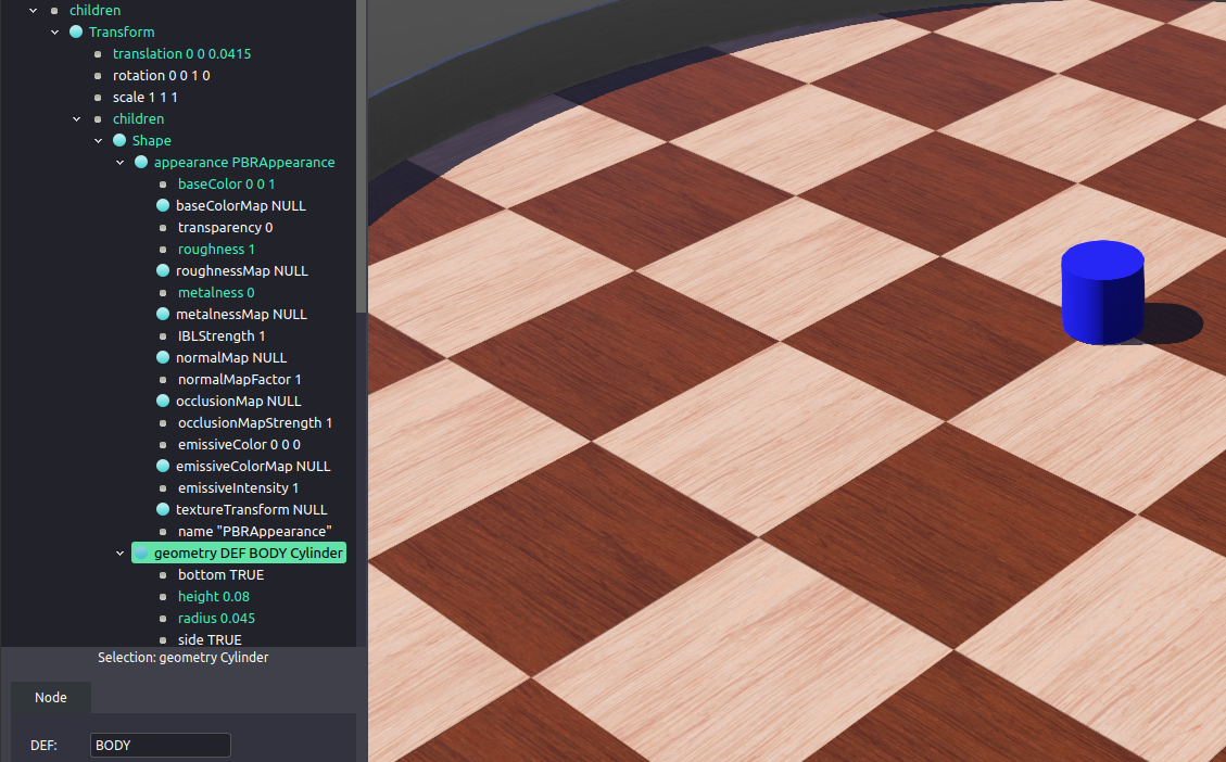
In the Cylinder node set the height to 0.08 and the radius to 0.045.
Click on the Cylinder node and in the DEF field (under the scene tree) type BODY.
This DEF_USE mechanism permit you to define the parameters of this cylinder with DEF and to reuse these parameters later with USE.
Select the appearance field of the Shape node and add a PBRAppearance node.
Expand the PBRAppearance node, click on baseColor and chose a color for the body of your robot, so you will be able to distinguish this part.
Also set the roughness to 1 and metalness to 0 to have a better visual aspect.
You should have the following setup at this point:
To the boundingObject field of your robot add a Transform node.
Set also the translation of this Tranform to 0 0 0.0415.
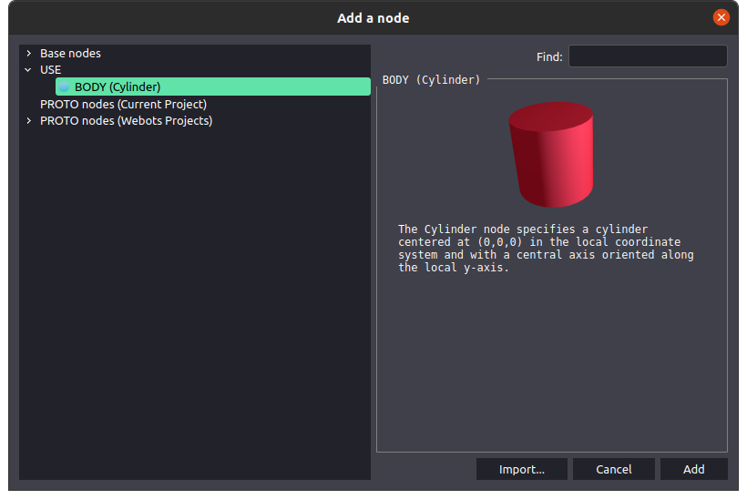
Inside this new node add to the children field the BODY node you defined previously (you will find it in the USE list).
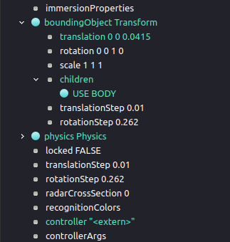
Add to your robot a Physics node to the field physics in order to enable the collision with other objects.
Then, select the field controller > Select... > <extern> to indicate to the simulator that the controller used will be extern to Webots (as you will use a ROS node).
You should end with this setup for the second part of the body of your robot:
Now you will add the wheels to your robot so it can move.
Let's start with the left one.
Select Robot > children and then add a HingeJoint node.
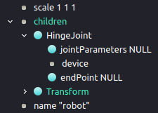
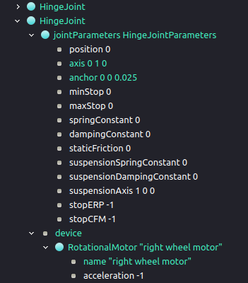
Next select jointParameters and add a HingeJointParameters node.
Select device, add a RotationalMotor node and configure the HingeJointParameters and RotationalMotor nodes in the same it is depicated below.
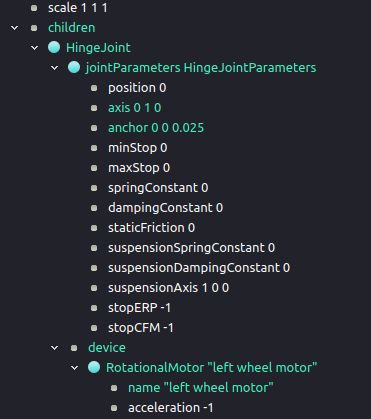
axis will indicate around which axis the wheel should rotate and anchor indicates an offset between the axis of the wheel and the base of the robot.
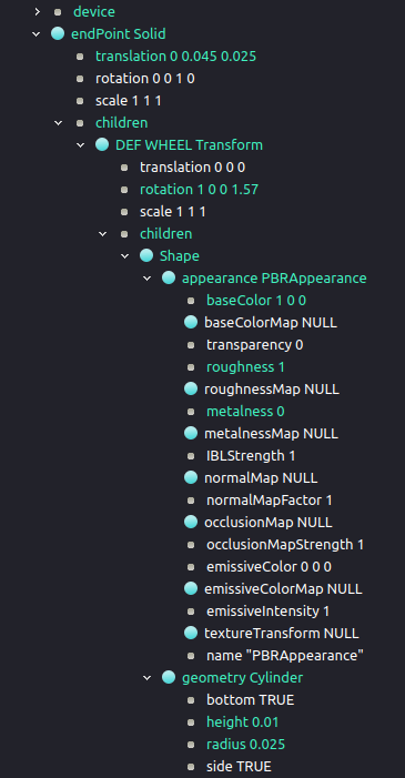
Select endPoint, add a Solid node and set it up like here in a similar manner you did for the body of the robot:
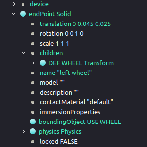
Change the name to left wheel and add to the boundingObject a WHEEL node (you will find it again in the USE list).
Add to your endPoint Solid a Physics node to its field physics once again in order to enable the collisions.
You should end with the following for the endPoint Solid node.
Creating the second wheel is easier as you can use the DEF-USE mechanism of Webots.
Select Robot > children > HingeJoint and add a HingeJoint node.
You have to select the first HingeJoint in order to have the second HingeJoint below.
This will enable to correctly benefit of the DEF-USE mechanism as you can only have a USE if there is a corresponding DEF defined above in the scene tree.
Once again select jointParameters and add a HingeJointParameters node.
Select device, add a RotationalMotor node and then configure the HingeJointParameters add RotationalMotor nodes like below.
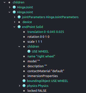
Select endPoint, add a Solid node and inside the new children add the WHEEL node.
Then change the name to right wheel and add to the boundingObject another WHEEL node.
Finally add to your robot a Physics node to its corresponding field.
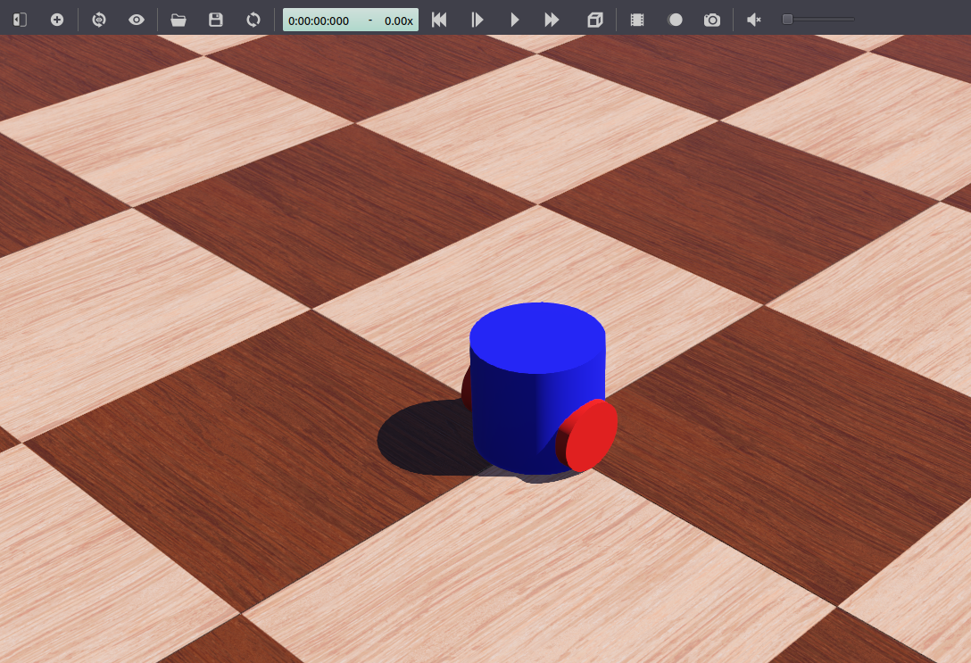
Congratulations!
You have now a simulation with a simple robot that can move around in the arena.
Do not forget to save your file with Ctrl+S.
Your robot is now able to move but it will not be able to avoid obstacle.
Let's add some sensors in order to make the robot able to detect front obstacles.
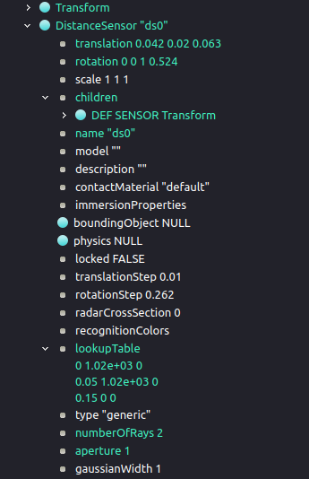
Start by adding a DistanceSensor node in the children field of your robot.
Then, configure the sensor as described in the following image in order to correctly place and model the sensor:
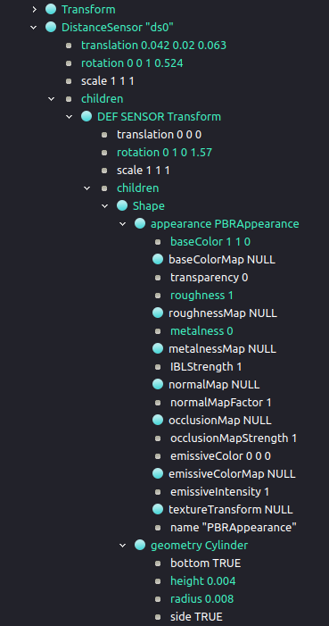
Next rename the sensor and configure the lookupTable, the numberOfRays and the aperture field.
You might need to press lookupTable > Ctrl+Shift+A in order to add a new line in the lookupTable field.
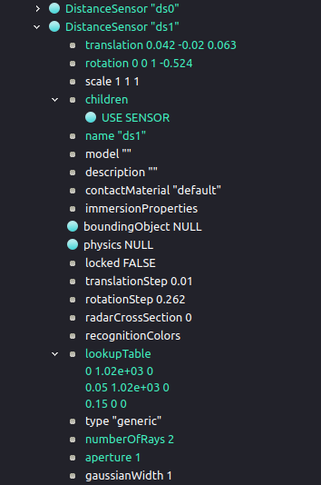
Creating the second sensor is straightforward and you can follow this structure (you might copy/paste ds0 DistanceSensor and adapt it):
Now you can confirm that your sensors are well modeled by going to View > Optional Rendering > Show DistanceSensor Rays or pressing Ctrl+F10.
You should see two white lines per sensor in a horizontal plan in front of your robot.
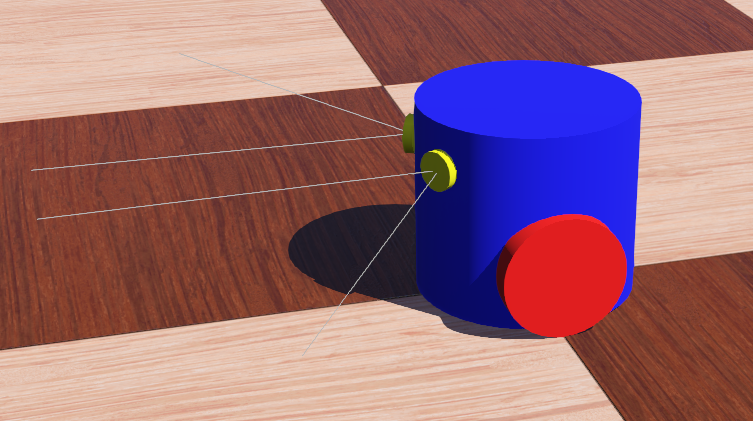
Perfect, your robot is ready! Do not forget to save your world with Ctrl+S.
You can check your implementation by downloading here the world file with the robot inside.
After you ensured the new robot model is working properly you can create a ROS 2 interface for it in a few simple steps:
- Start the simulation.
- Execute
ros2 run webots_ros2_driver driver.
The driver node will attach to the Webots robot and create a ROS 2 interface for it.
For more details on how to improve the ROS 2 interface please follow the tutorial Creating a Custom Package.