vB5 CubeSat Frame - alanbjohnston/CubeSatSim GitHub Wiki
The 1U frame for the CubeSat Simulator is 3D printed.
Here is a link to the STL files that you can use to print your frame. Or, if you don't have access to a 3D printer, you can follow the "Order This Printed" link to have one printed and mailed to you. PLA is the simplest material, but you could try others.
EDIT: The "Order This Printed" button seems to have disappeared. Instead, download the Universal+1U+CubeSat+for+CubeSatSim.zip file from Thingiverse, then upload it to https://print.all3dp.com/. Select "See Materials and Prices" and select PLA, and you can then get it printed and shipped to you!
I also like this 3D printed 3.5mm plug for the RBF switch. https://www.thingiverse.com/thing:10295 It is useful for shipping or other situations where you want to ensure the CubeSatSim is powered off but don't want the RBF tag attached.
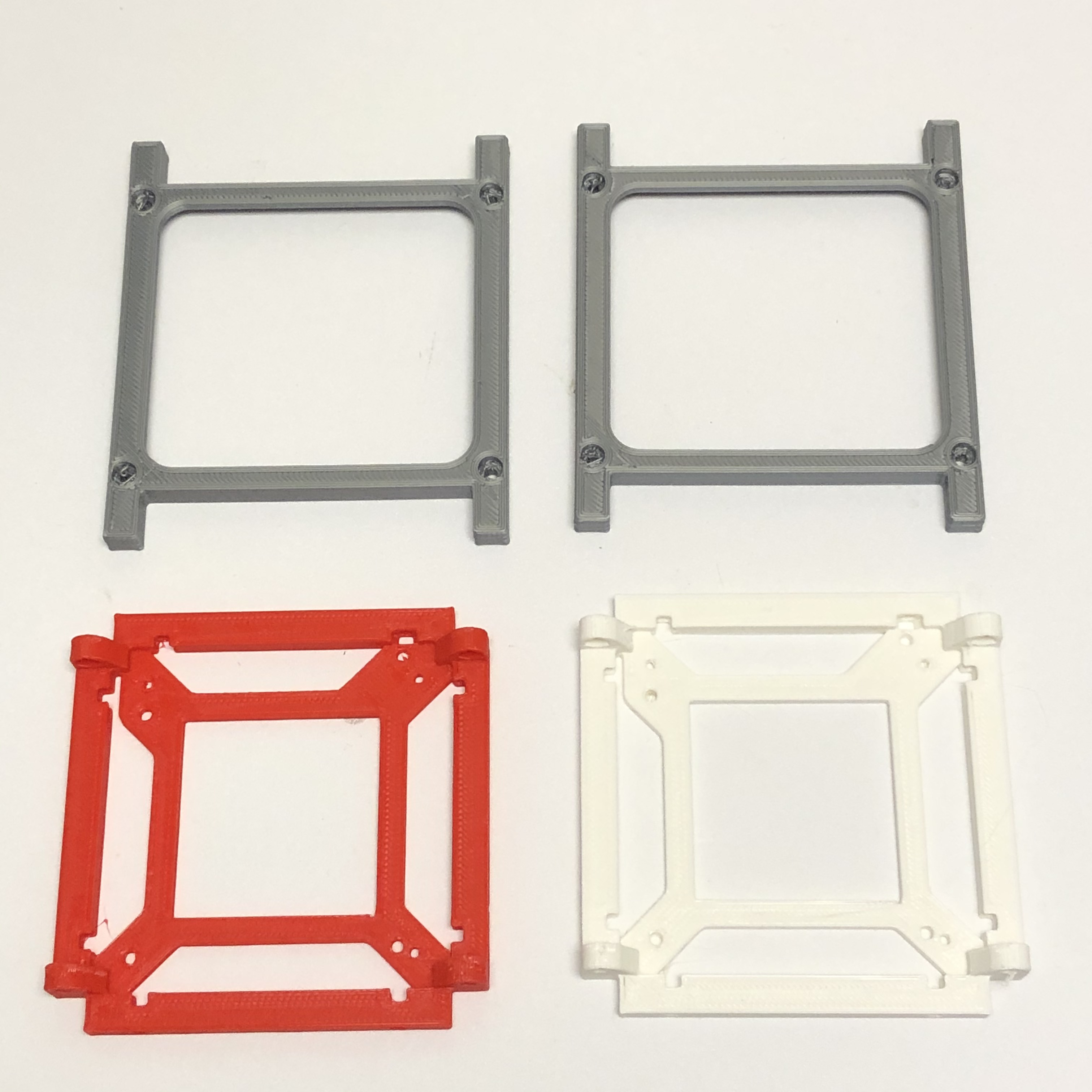
Here are the 3D printed parts:
 .
.
It will hold together by itself, but if you want a sturdy frame you can use four M3 x 10mm screws and nuts.
Solder the female JST RCY connectors onto each of the solar cells, red to +, black to - side. Connect the JST RCY connector to the JST 2.0mm wires.
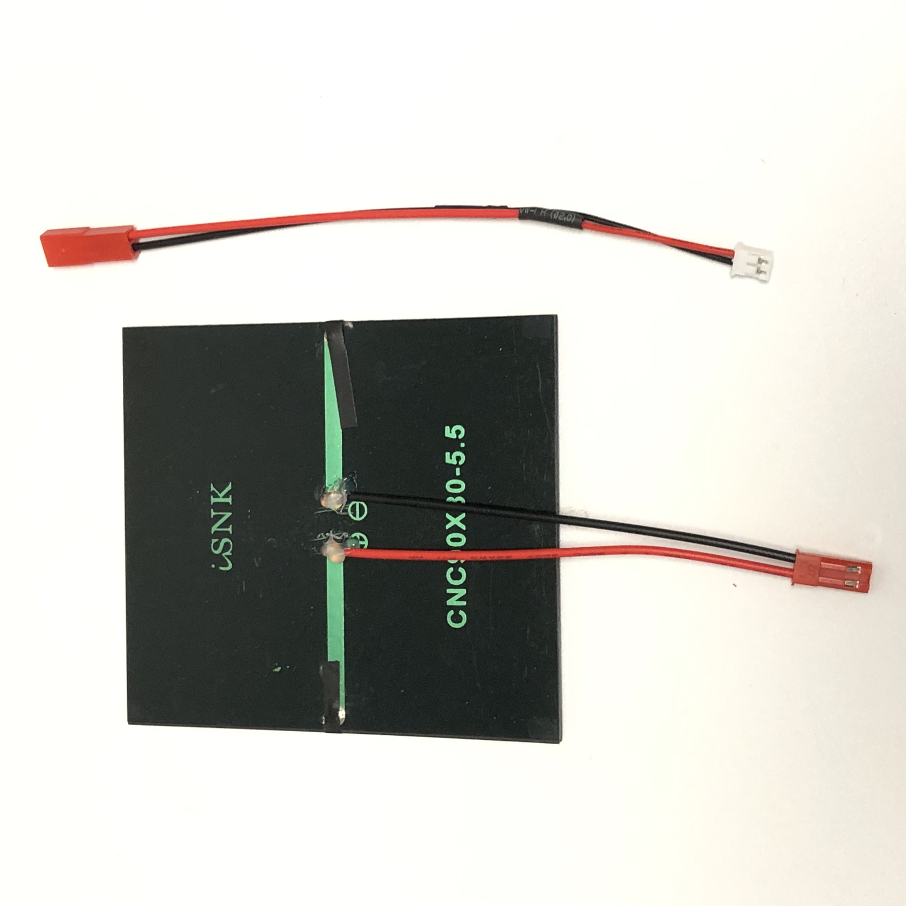
Hot glue the wire insulation to the solar panel - this will provide strain relief so the wires don't pull out.
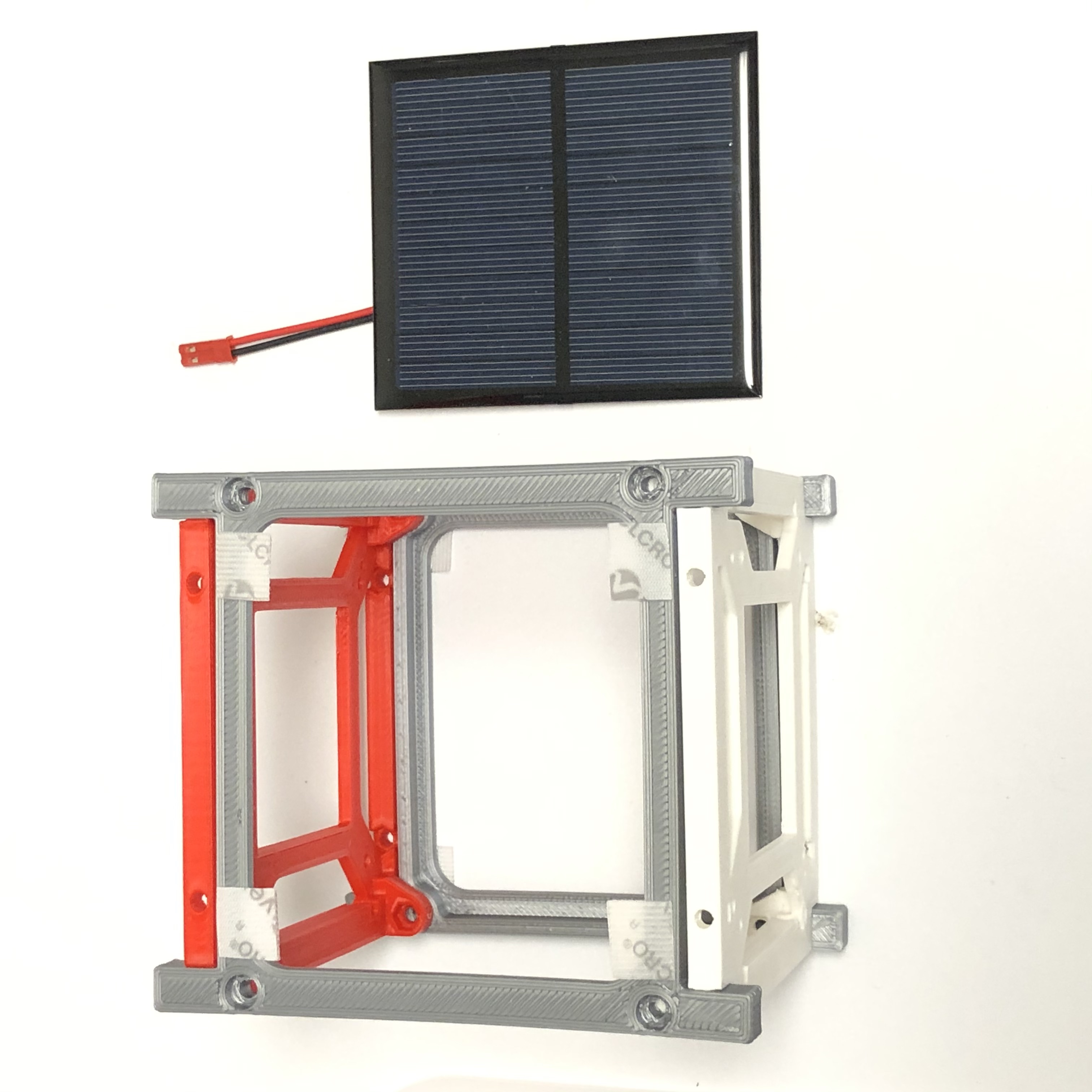
You might want to test the solar cells before soldering and mounting them. Cut four small 3mm square pieces of the Velcro for each cell and stick on the back of the four corners. Remove the paper and stick them onto the panel. The panels can be centered, except for the +X panel (with the hole for the RBF) which will need to be raised slightly or the holes will be covered. Also make sure the holes and slots on the top are not covered. Don't stick any of the side solar panels to the top frame or you won't be able to remove the top and remove the board stack without removing all the solar panels. The JST RCY connector wires should feed inside the frame.
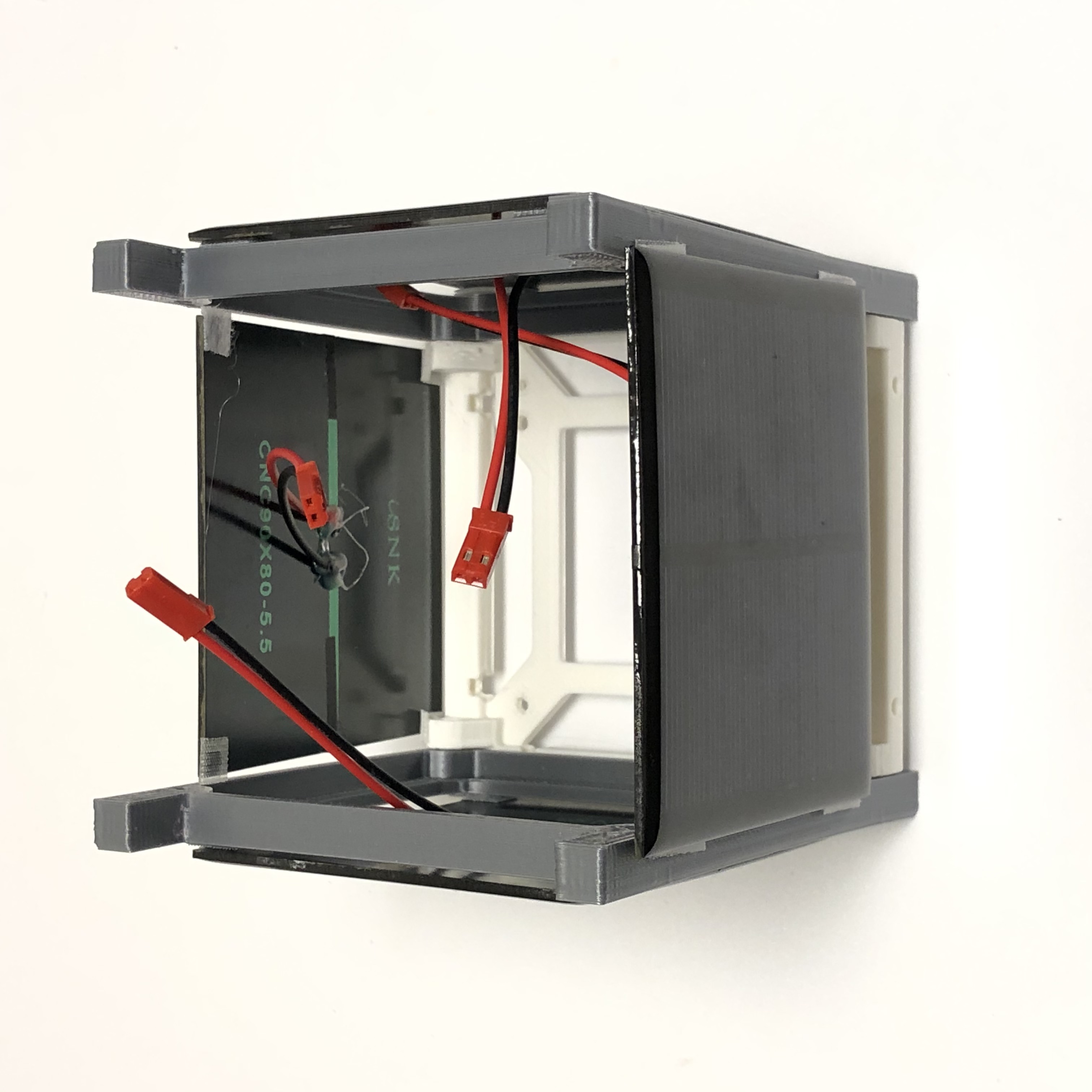
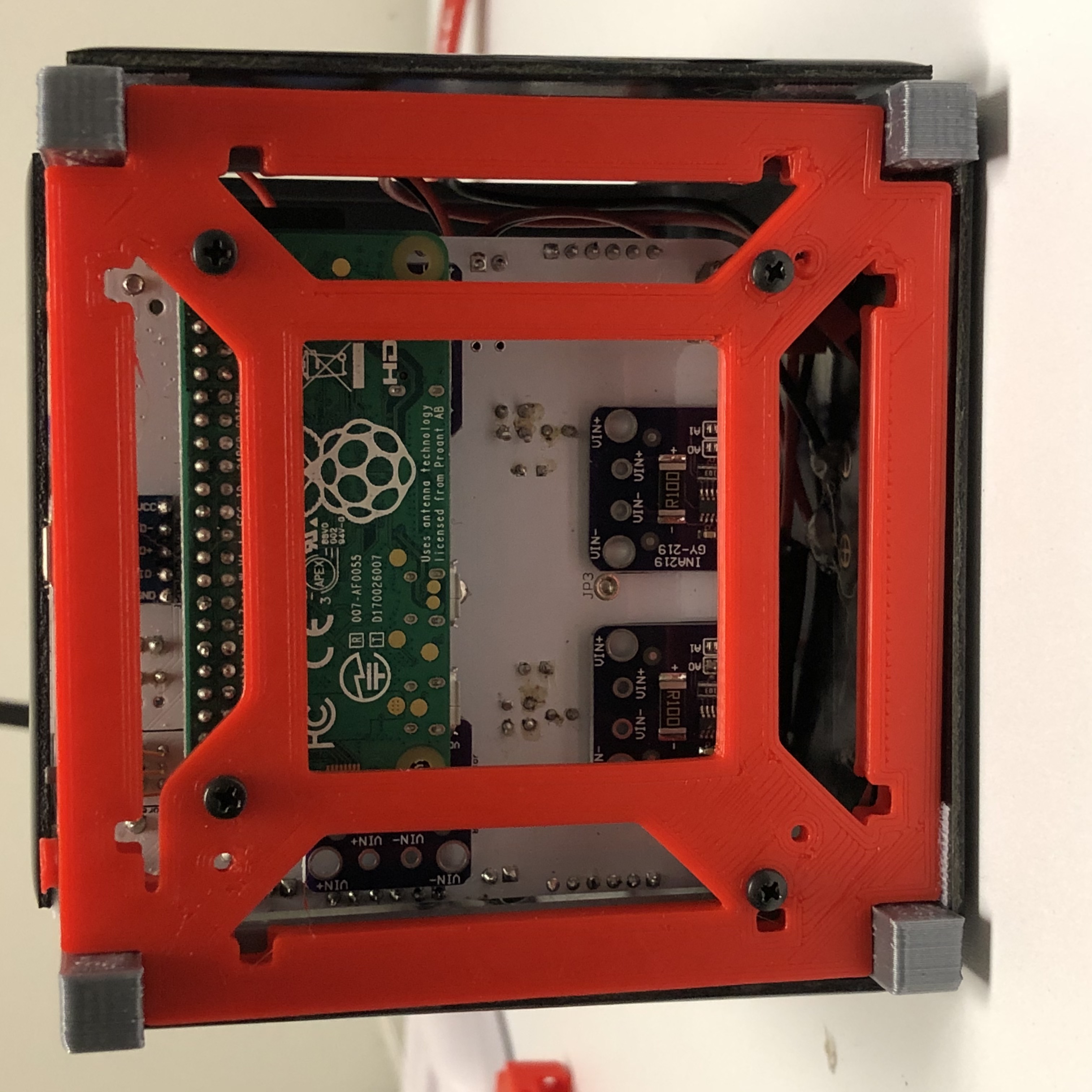
The view inside the frame should look like this:
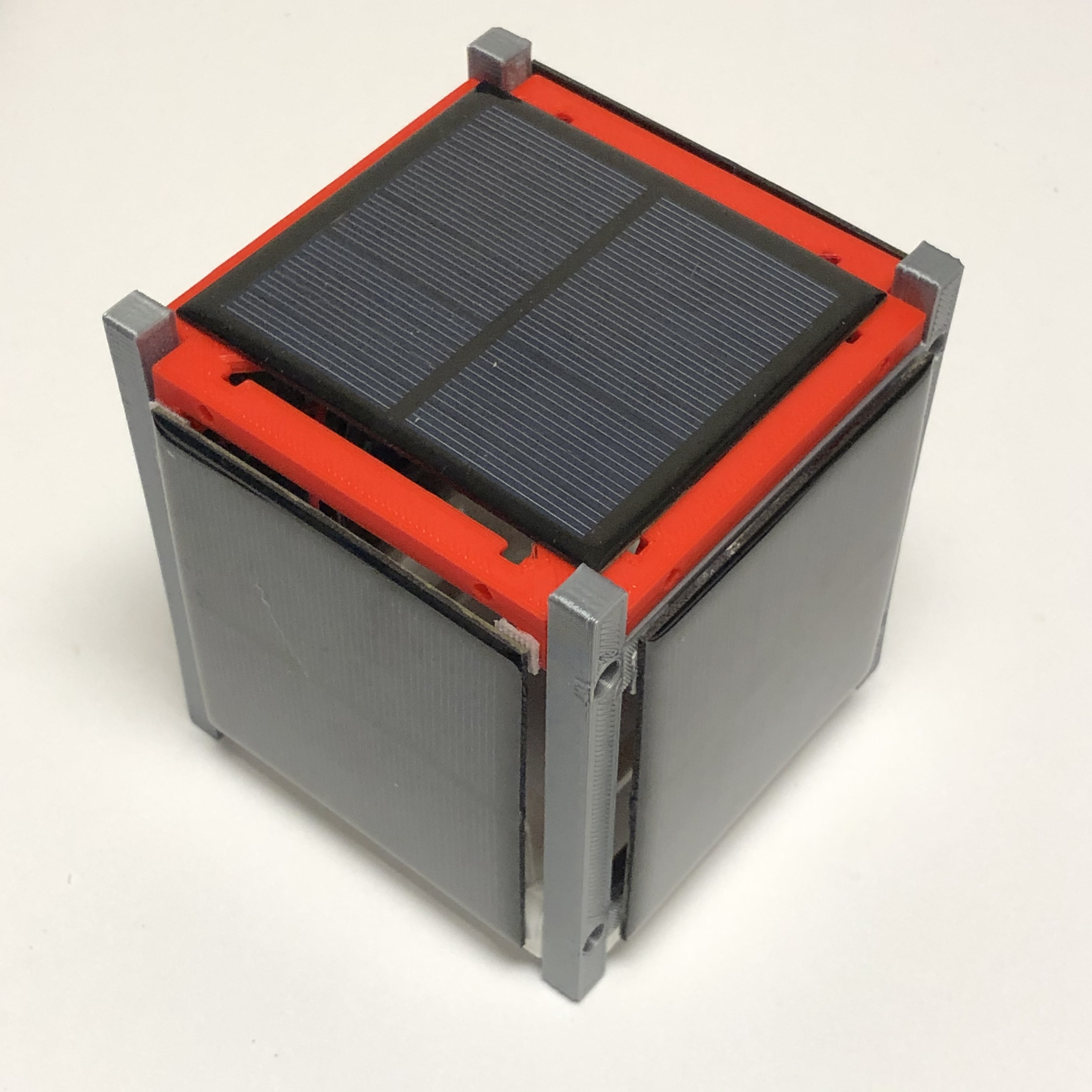
The complete frame should look like:
With the top off, you can lower the board stack into the frame. The board stack attaches to the frame via four screws through the bottom of the frame as shown here:
Note that the mounting hole which is a single hole is used for the post closest to the antenna on the board.
Follow the Assembly Instructions for the Board Stack