vB3 CubeSat Frame - alanbjohnston/CubeSatSim GitHub Wiki
The 1U frame for the CubeSat Simulator is 3D printed.
This is not the latest version of the CubeSatSim. You can find it here.
You will also need to mount the antenna on the top and the push button switch on the top as well.
Here is a link to the STL files that you can use to print your frame. Or, if you don't have access to a 3D printer, you can follow the "Order This Printed" link to have one printed and mailed to you.
EDIT: The "Order This Printed" button seems to have disappeared. Instead, download the CubeSat+Simulator.zip file from Thingiverse, then upload it to https://print.all3dp.com/. Select "See Materials and Prices" and select PLA, and you can then get it printed and shipped to you!
Here are the 3D printed parts:
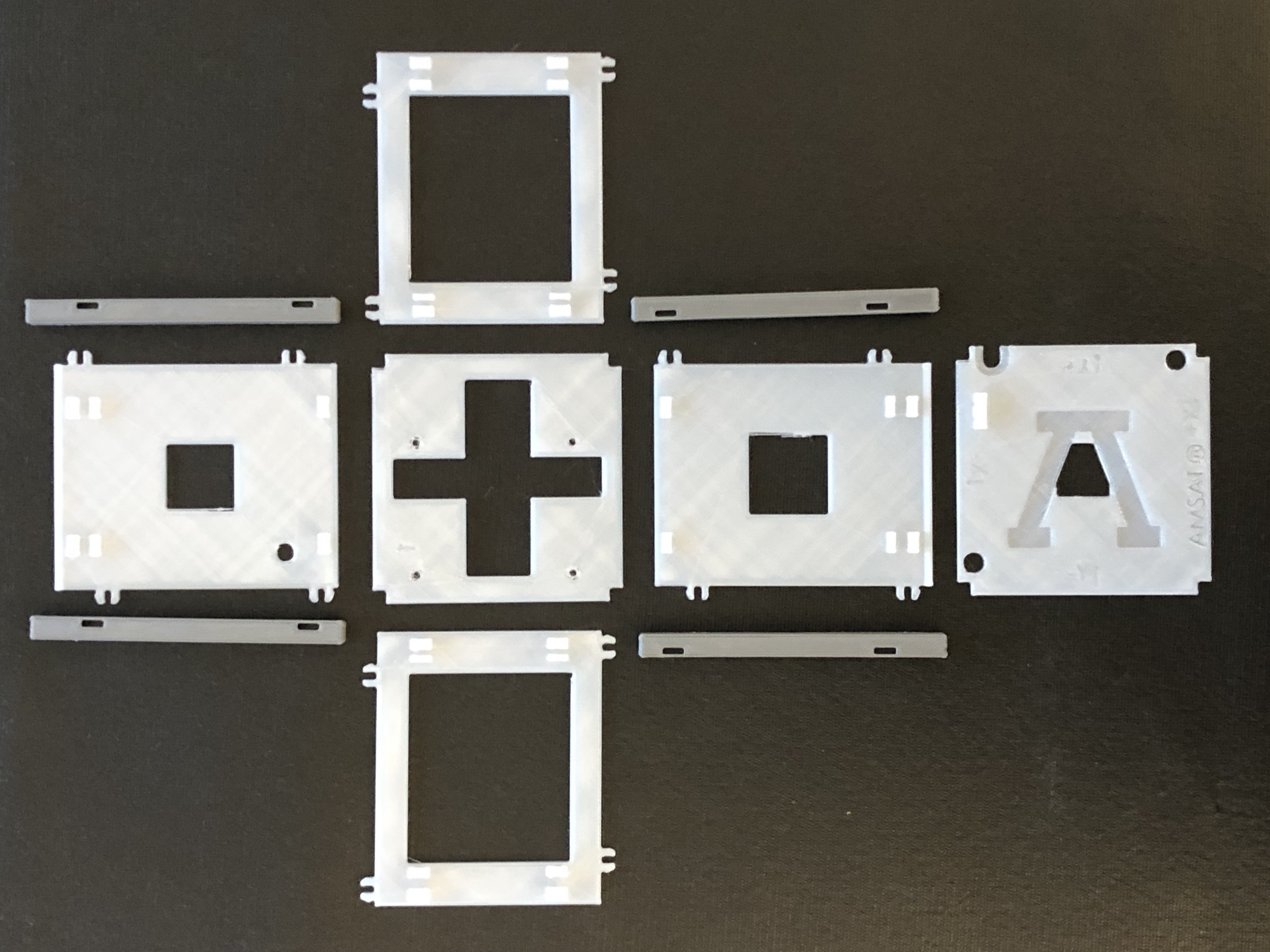
You will likely need to clean out some of the holes and notches with a knife or file before assembly.
Here are the steps for the a particular printer (Lulzbot TAZ 6) - the steps for your printer will be similar.
-
Download and install Cura for Lulzbot
-
When you run Cura the first time, it will prompt you to install a printer - select Lulzbot TAZ 6.
-
On the upper right side of screen, it should say Lulzbot TAZ 6. Under catagory choose All. Under Material choose PLA (Verbatim). Under Profile, choose Standard - 0.25mm
-
Download the STL files for frame. We print the rails in grey and the remaining sides, top, and bottom in translucent. Click on the Open File on the right hand side and select your downloaded file. You will most likely have to Rotate the part until it is flat (you can't print it standing vertically - it will fall over!). A 90 degree rotation on the X axis should do the trick. Place and arrange the parts. Make sure they are all on the bed - they will be a solid color when resting on the bed, and a grey cross hatched color when they are not.
-
Next to Print Setup, click the Custom button . Scroll down and click on Material. Scroll down and click on Support. Make sure support is not enabled.
-
Click Save to File and save your gcode file. Note down the print time - it is a good idea to put this in the filename as filename_xh_ym.gcode where it will take x hours and y minutes to print.
-
On the printer, load the PLA material (grey or translucent, depending on the part). If you need to change spools, set the Nozzle temperature to 240 degrees, loosen two clamp nuts, and move the wheel backwards to back out the existing material. Rewind remaining onto the spool and poke the end through a hole so it does not unwind. Feed in new spool, and push through nozzle until the right color comes out. Retighten two clamp nuts.
-
Put your gcode file on the SD card (you might need a USB SD Card reader) and insert in the printer. Select Print from SD and select your file.
-
Watch it start printing at least two layers to confirm that it is sticking to the bed properly before leaving. Come back in x hours and y minutes (noted from Cura or from the gcode filename) and remove the print and take off the spool.
Carefully identify the parts. The bottom has the + shaped opening, and the top is identified by a "T". The side with the "T" must face the side panel with the hole for the RBF switch in it. The sides snap into the post pieces after the bottom has been put in place. Once the four sides have been snapped in place, test fit the top, but do not finally snap it in place.
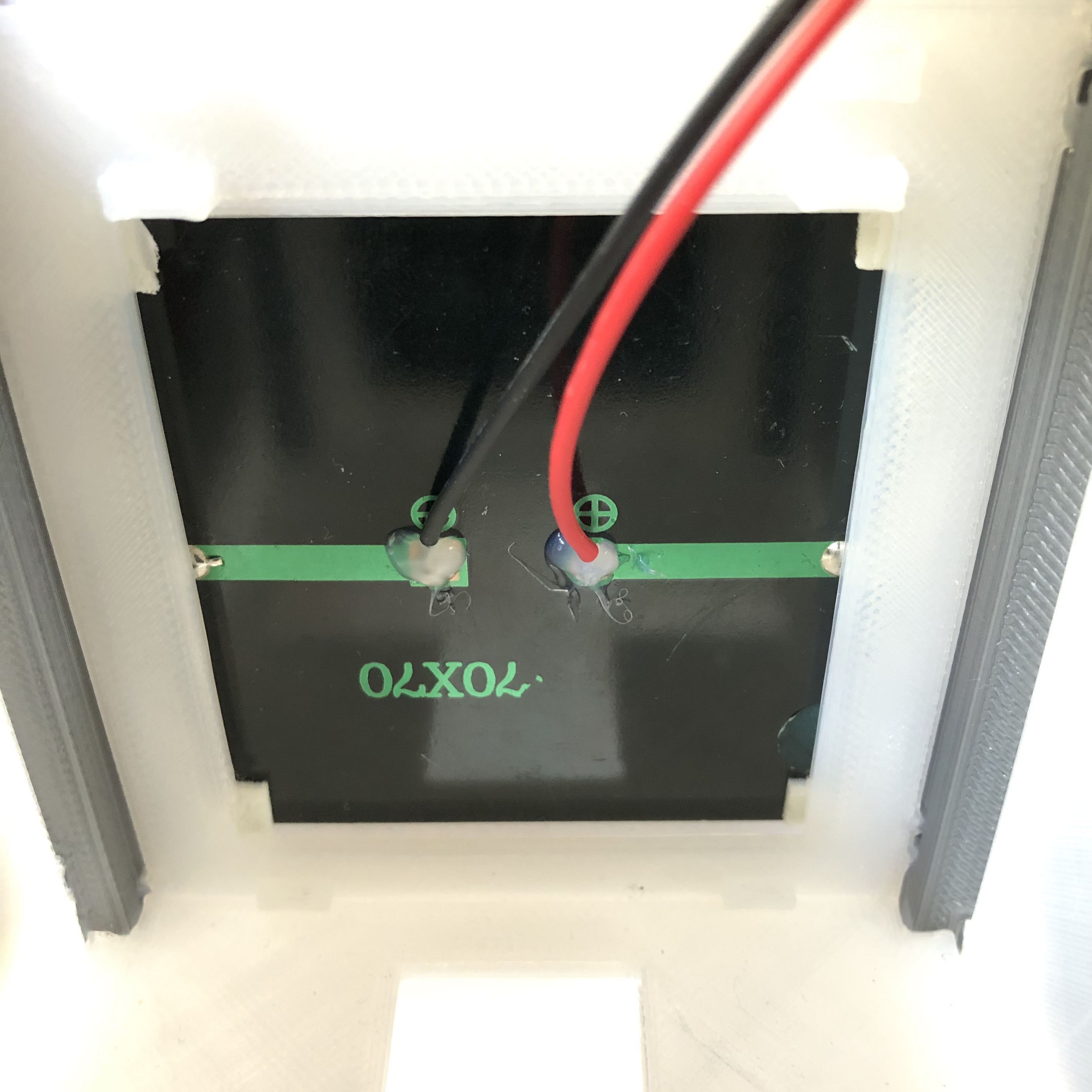
Solder the female JST RCY connectors onto each of the solar cells, red to +, black to - side. Hot glue the wire insulation to the solar panel - this will provide strain relief so the wires don't pull out. It should look like this when you look down into the frame:
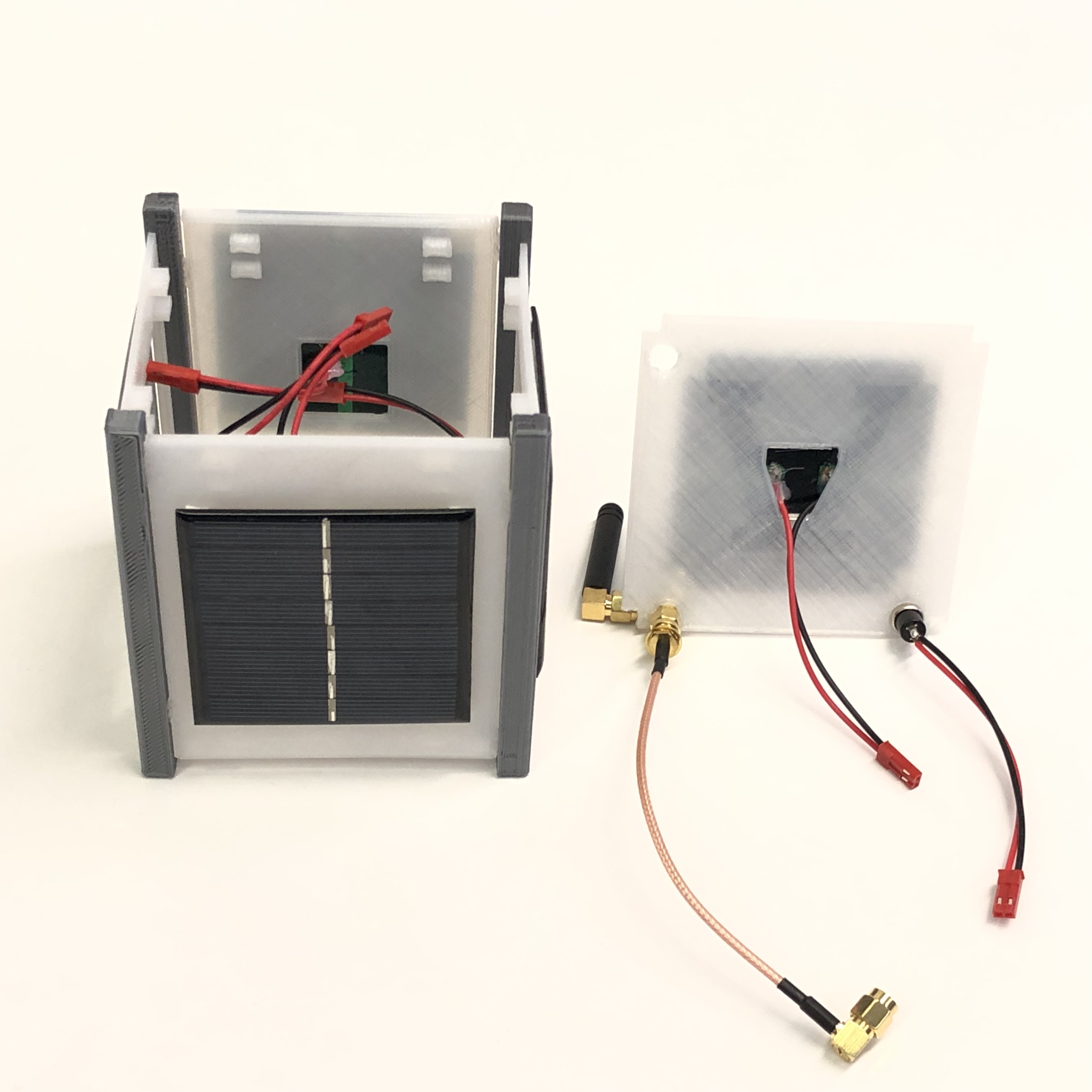
You might want to test the solar cells before soldering and mounting them. Cut four small 3mm square pieces of the mounting square for each cell and stick on the back of the four corners. Remove the paper and stick them onto the panel. The panels can be centered, except for the +X panel (with the hole for the RBF) which will need to be raised slightly or the holes will be covered. Also make sure the holes and slots on the top are not covered. The JST RCY connector wires should feed inside the frame.
Attach the SMA male to female coax and the right angle SMA adapter to the Digital Transceiver Board.
Solder the momentary push button switch to a female JST RCY connector, ready to plug into the MoPower board. The complete frame should look like:
Make sure the nut is not present on the RBF switch - it is not used.
Follow the Assembly Instructions