v1.3 6. Solar Panels and Frame - alanbjohnston/CubeSatSim GitHub Wiki
6.1 Assembling and Testing the Solar Panels
These instructions are for the Solar Panels.
You will need these tools:
- Safety glasses (to protect eyes while soldering or trimming leads)
- Soldering iron and solder (I use lead-free solder, but leaded solder is easier to work with)
- Side cutters (to trim leads)
- Wire strippers or a blade (to remove insulation from wires)
- Heat gun or hairdryer (to secure heat shrink tubing over connector wires)
Other tools that are helpful:
- Multimeter (to read solar panel voltage)
Video
Here is a video on the CubeSatSim Solar Panels:
Checklist
The BOM has a sheet "By Steps" which lists the parts needed for each step in order. If you have a Google account, you can make a copy of this spreadsheet ("File" then "Make a Copy") and check off each part as you install it.
For example, here is the checklist for this step:
Solar Panels
These instructions are for soldering, testing, and trial mounting on the space frame.
Video
Here is a video of this step.
Any solar panel that is 5V - 6V and less than 90mm (45mm if two panels are used) in length will work. For side with the camera and the side with the pushbutton, USB-C charging port, and the LEDs, the longest dimension of the solar panel is 45mm.
The recommended solar panels are 72mm x 45mm, and there are two mounted on each side, except the top and bottom that have just one. (You can also mount two solar panels on the top and bottom, although the solar panels are commonly sold in batches of 10.
Your set of solar panels may contain a mix of panels.
Solar Panel Soldering.
Before using any of your JST connector wires, make sure they have the correct polarity. There is no standard in the industry for red and black, unfortunately, and some suppliers will supply different polarities in different orders. Verify your polarity against this image, and swap if they are reversed:
The 10 solar panels need to have the JST 2.0 connectors soldered on:

Some liquid flux can be applied to each pad of the solar panels to make soldering easier. Also, hot glue can be used to stick the insulation of the wires to the panel to provide extra strength.

Here's how the panels look after the protective film is removed:

Solar Panel Testing
The solar panels are tested with the Digital Multi Meter (DMM). They should be tested in constant illumination such as from the LED lamp.
Open Circuit Testing
Open circuit testing measures the maximum voltage output. Put the DMM on the DC volts scale and measure while illuminated.
Test each panel to make sure they work.
Note down the maximum voltage for each size of solar panel.
Short Circuit Testing
Short circuit testing measures the maximum current output from the solar panel. Put the DMM in DC Current (or Amps) mode and measure across the red and black leads while illuminated.
Test each panel to make sure they work.
Note down the maximum voltage for each size of solar panel.
The Solar Panels are now ready for the next step V2 Frame
6.2 Printing the CubeSatSim Frame
Frame Print
Here are the v2 Frame STL files: https://github.com/alanbjohnston/CubeSatSim/tree/pico/hardware/framev2
You need to print two of each.
Frame Test Assembly with Solar Panels
In this step, we will do a Frame test assembly and mount some of the Solar Panels on the Frame.
Video
A video of this step is available here.
Here's the frame parts with the ten Solar panels, plastic screws and nuts, and velcro to secure the panels to the frame:
The 1U frame of the CubeSatSim has solar panels on each face, which are labeled by the Cartesian axes X, Y, and Z. For the sides that face in the direction of the axes (see https://en.wikipedia.org/wiki/Cartesian_coordinate_system#/media/File:Coord_system_CA_0.svg), they are labeled +X, +Y, and +Z. For the sides that face in the opposite direction, they are labeled -X, -Y, and -Z. The CubeSat Design Specification (CDS) standard also has drawings showing the X, Y, and Z sides of a 1U CubeSat https://www.cubesat.org/cds-announcement. Here is a figure from that document:
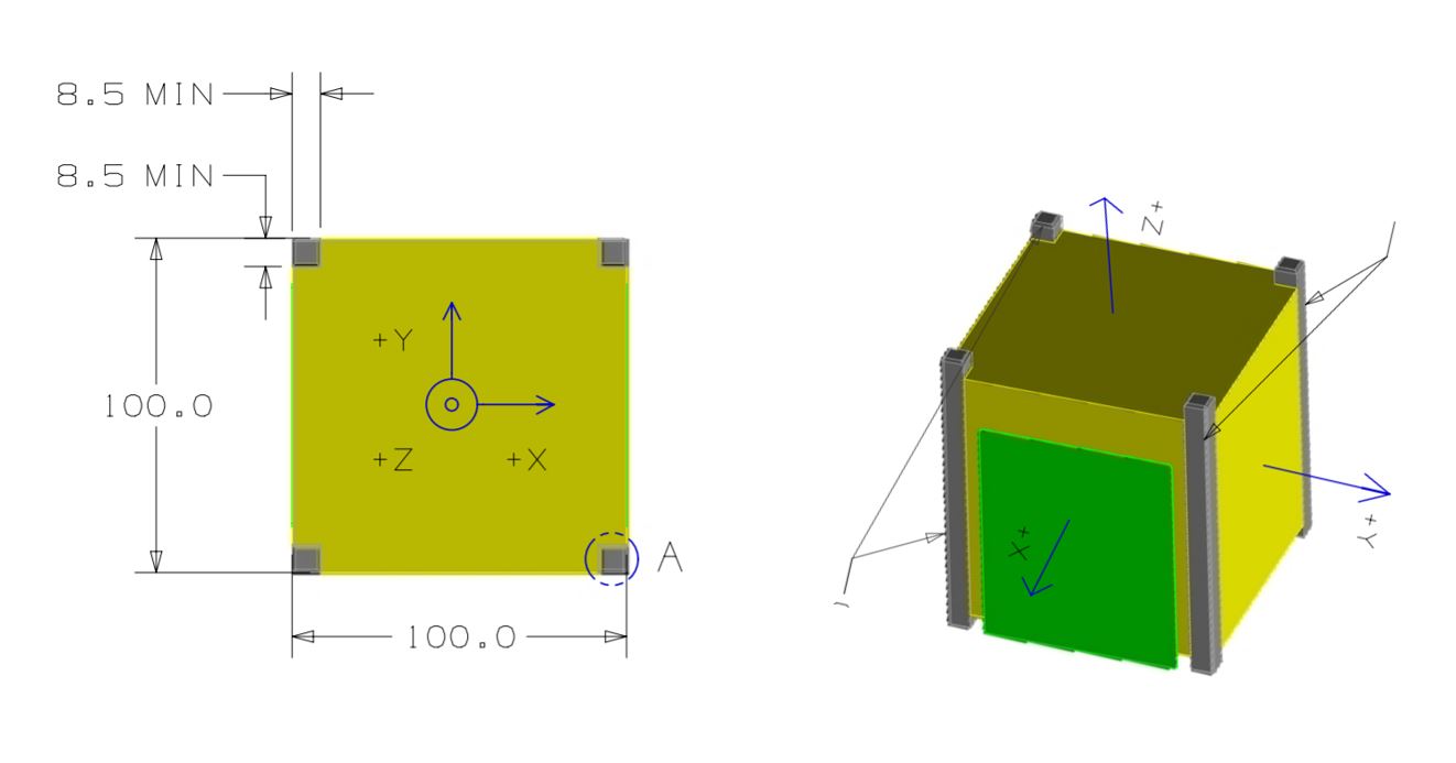
On the CubeSatSim, the +Z side is the top of the CubeSatSim, the +X side has the pushbutton, micro USB connector, and the LEDs. The Main printed circuit board has the axes labeled on it as well.
Start with the top and bottom of the frame (the +Z and -Z sides). One solar panel is mounted on each. Two strips of velcro or double stick tape are used to secure them, aligned with the ribs on the frame:

Here's how they look when mounted:

You can use a small amount of hot glue to mount the nuts in the top and bottom frame as you attach them. This prevents the screws from falling out when you disassemble the frame later in this step. However, be careful not to get glue in the threads.


Now get ready to attach the two sides to the frame bottom using the four plastic screws. Just start the screws - do not tighten them:
Attach the two sides to the frame bottom:

Here's how the solar panels will mount on the +X, -X, +Y, and -Y sides:

We will start with the +X side:

Attach the velcro or double stick tape to the horizontal frame parts:

Then attach the solar panels:

Now do the same for the -X side. Since it has the camera mount, only one panel can be attached:
If you are using the SMA antenna, mount the antenna and the coax on the +Z side as shown:


Put the +Z side on the frame and start the four screws.

We will mount the Solar Panels on the +Y and -Y sides when do our Final Assembly.
You can cut and attach the velcro to the frame sides for the +Y and -Y sides - just don't remove the film and stick to the +Y and -Y Solar Panels. This way, you will be ready to mount the +Y and -Y Solar Panels in the next step.
Remove the 8 screws holding the frame together and separate the four sides.
The frame is now ready for the Final Assembly in Step 8 Board Stack.
6.3 Pi Camera Instructions
Here are the parts you need for the Pi Camera:
- Side frame with camera mount
- Two small 80mm x 35mm solar panels (or 57mm x 28mm), wired in parallel
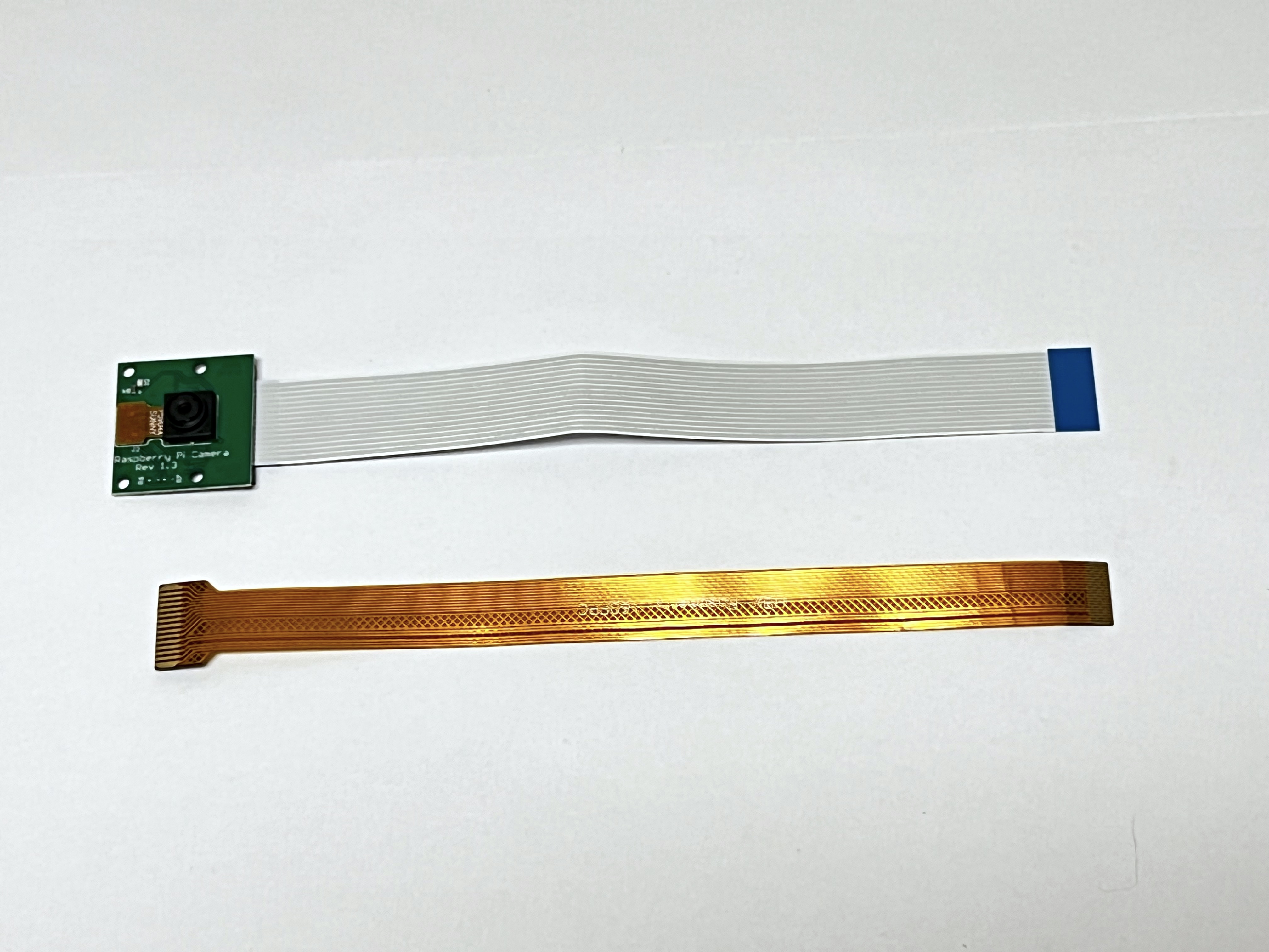
- Pi Camera
- 6.3 inch (16 mm) Camera cable for the Pi Zero W
Video
Here is a video on the Raspberry Pi Camera Installation: https://youtu.be/5ras2Y0Cfec
Most Pi Cameras come with the cable to connect to a full sized Pi, so you may need to buy a Pi Zero W Camera Cable as well:
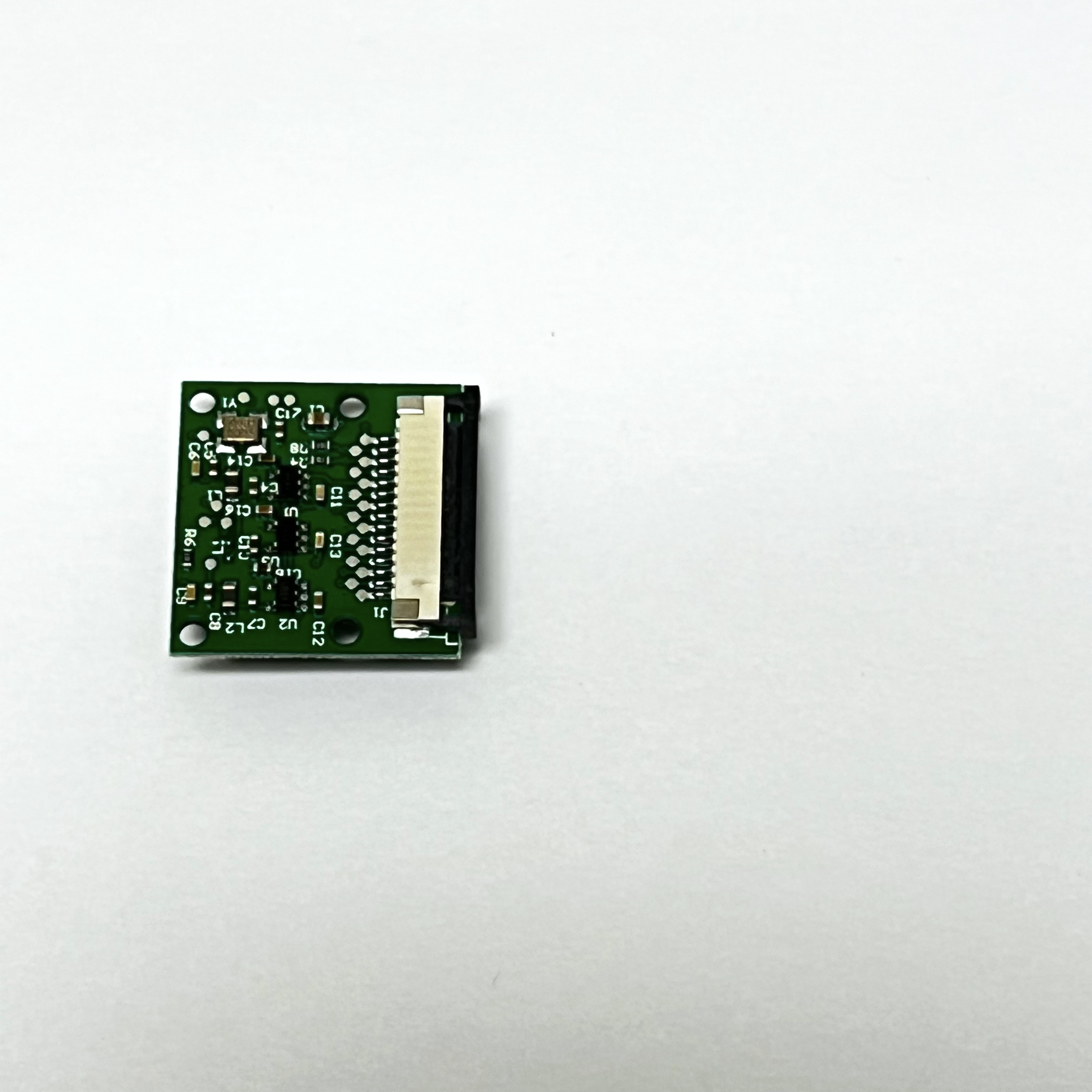
To disconnect the Pi Camera Cable, identify the slide lock on the connector on the back of the Pi Camera. In this photo it is the black plastic piece:
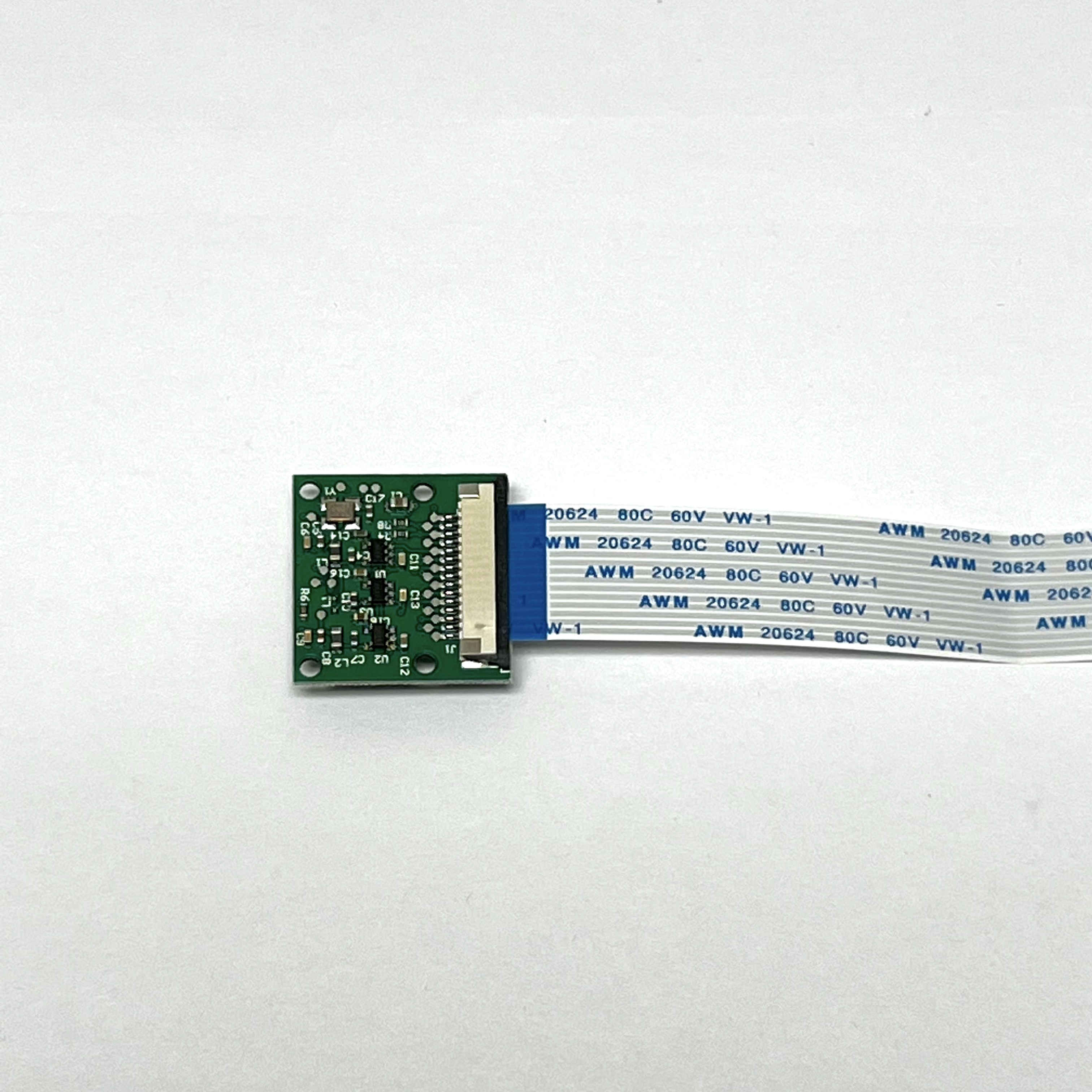
Carefully move the slide lock away from the board, to the left in this photo. You might need to move it a little on one side, then the other side. It only moves out a few millimeters and does not come completely off:
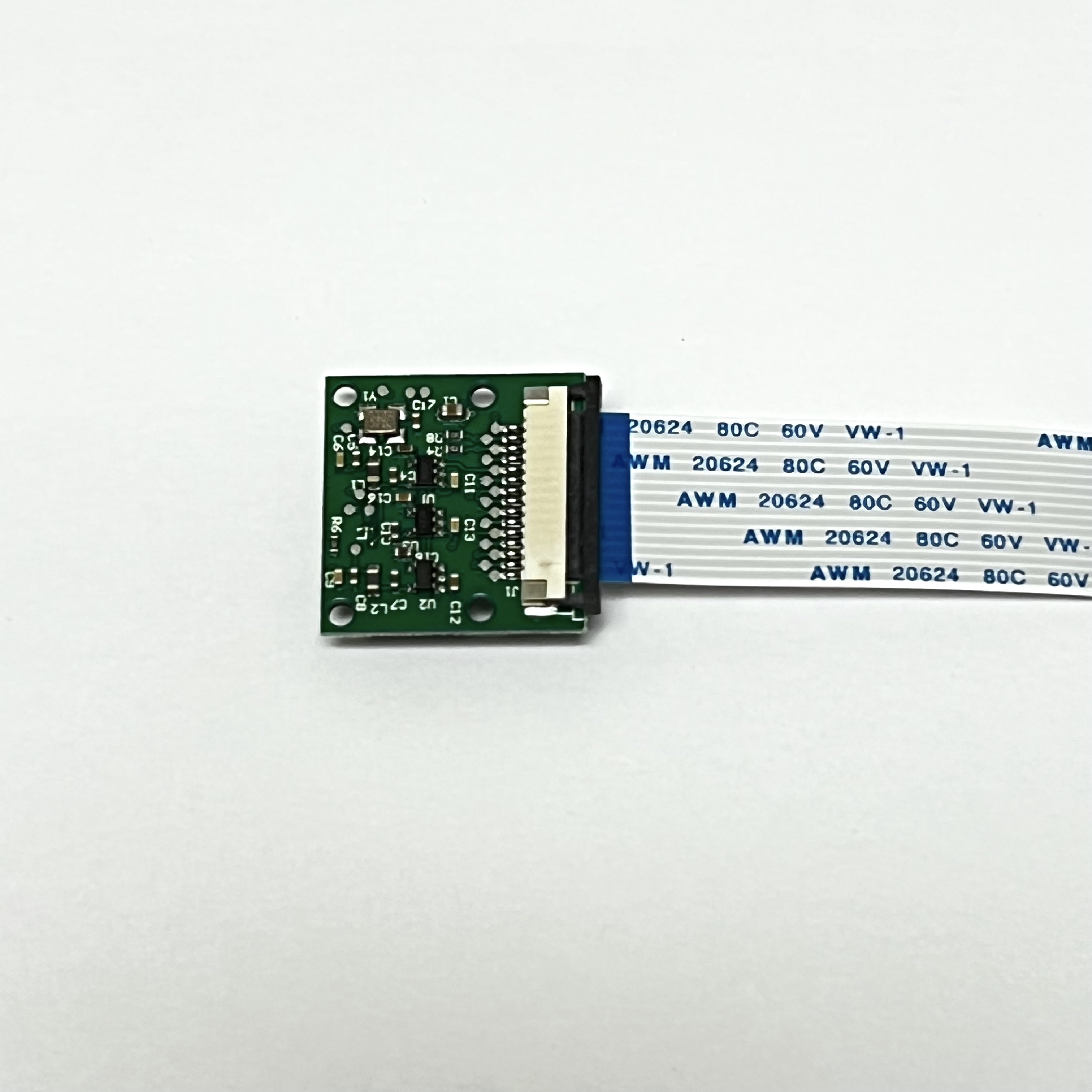
The cable will now be loose and you can slide it out and remove it.
Slide the 6.3 inch (16 mm) Pi Zero Camera Cable into the connector. Make sure the metal contacts on the cable are facing the PCB, in this photo the contacts face down:
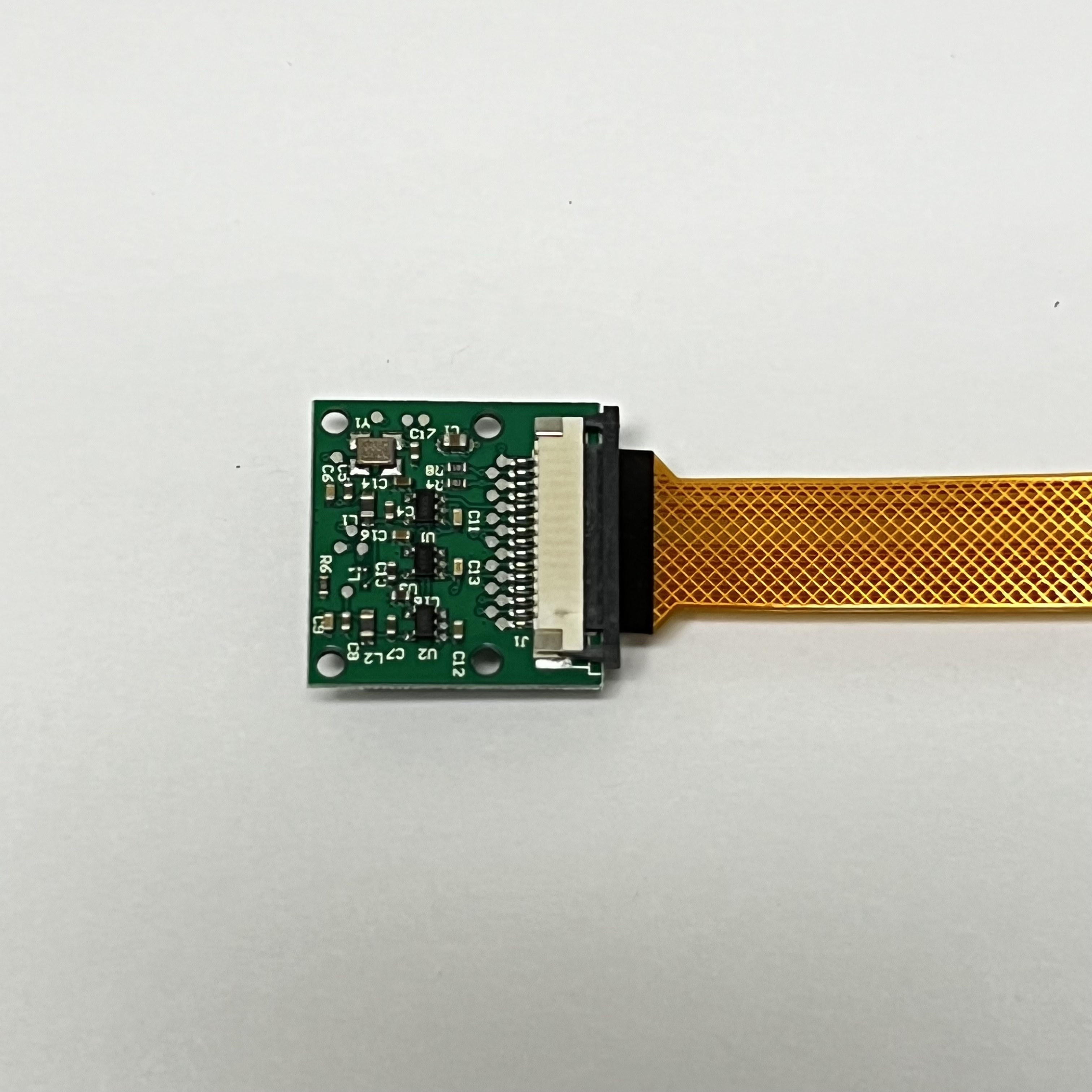
Carefully move the slide lock towards the board (to the right in this photo) to hold the cable securely. Make sure the cable doesn't slide over or get crooked:
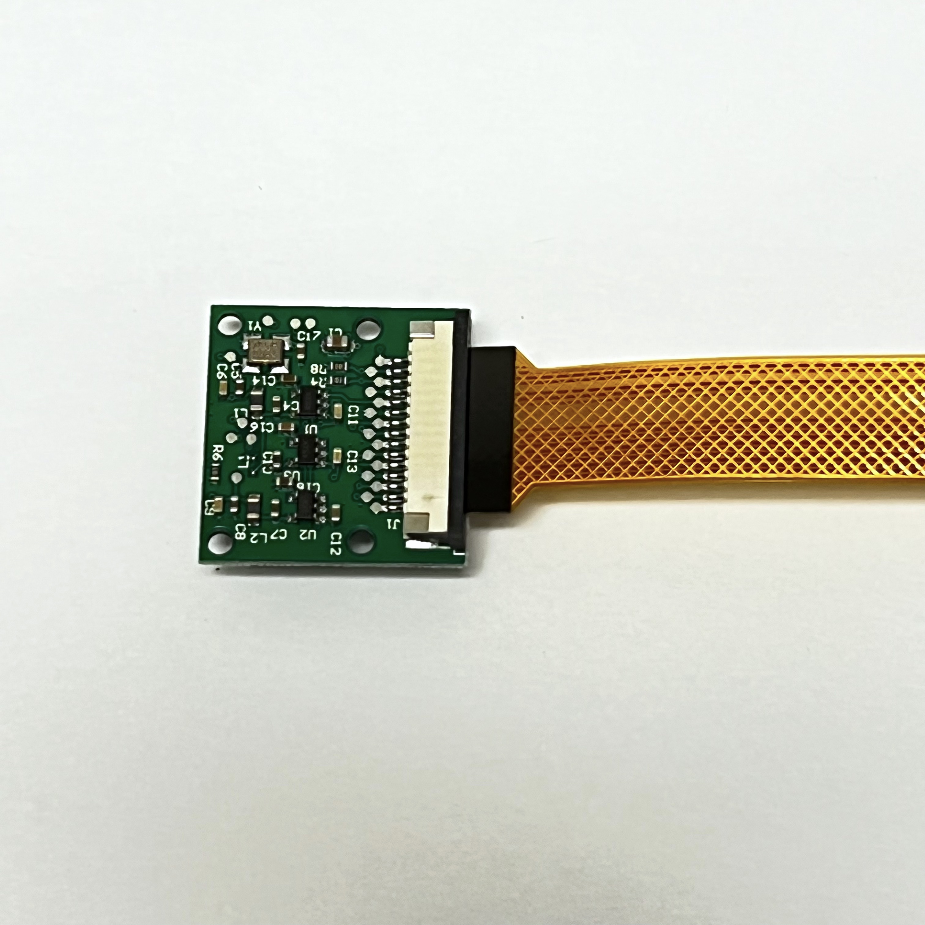
This is how it looks on the other side.
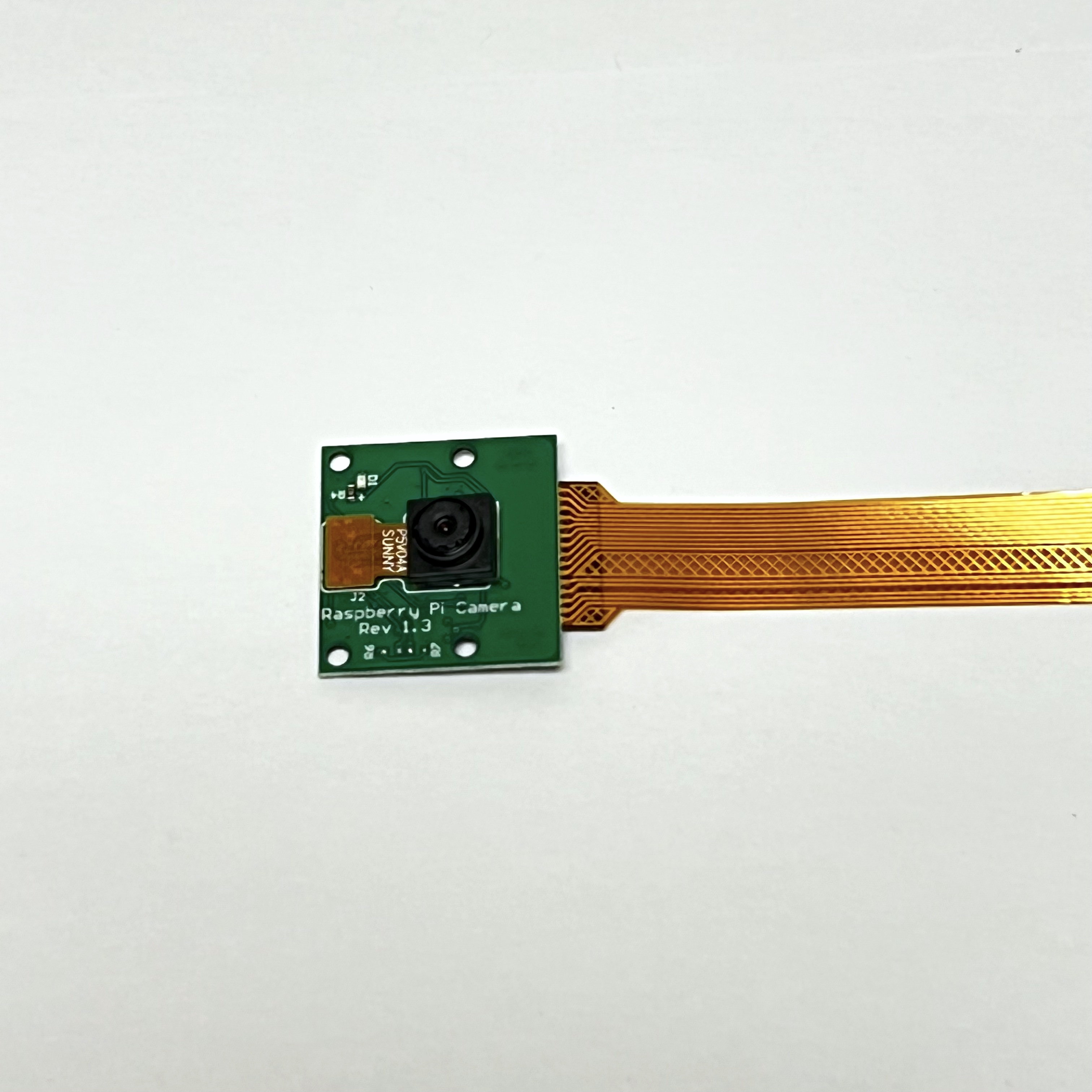
Don't forget to remove the plastic film over the camera lens!
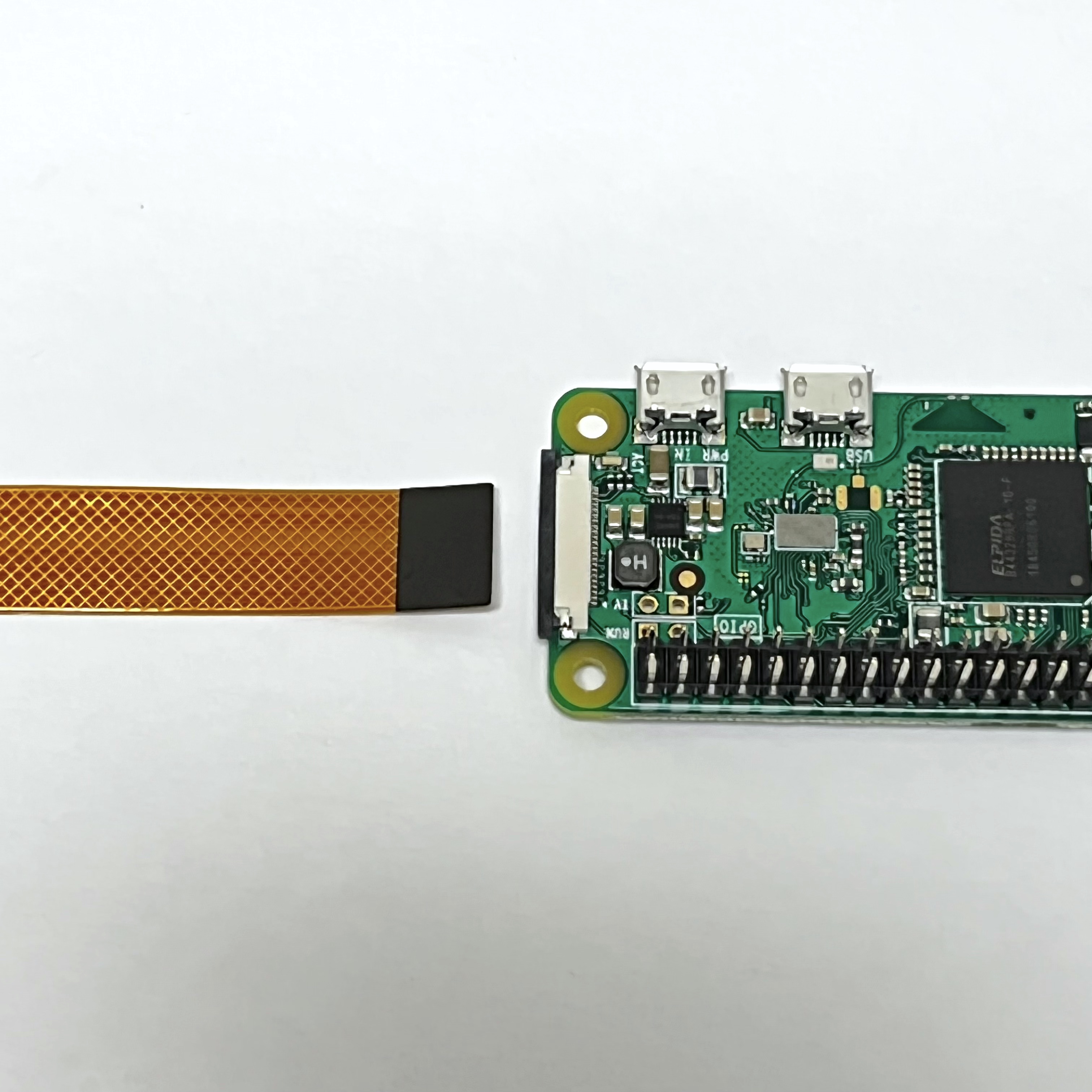
The camera cable plugs into the Pi Zero on the opposite side to the micro SD card. This is how the Pi Zero Camera Cable and the Pi look when ready to connect:
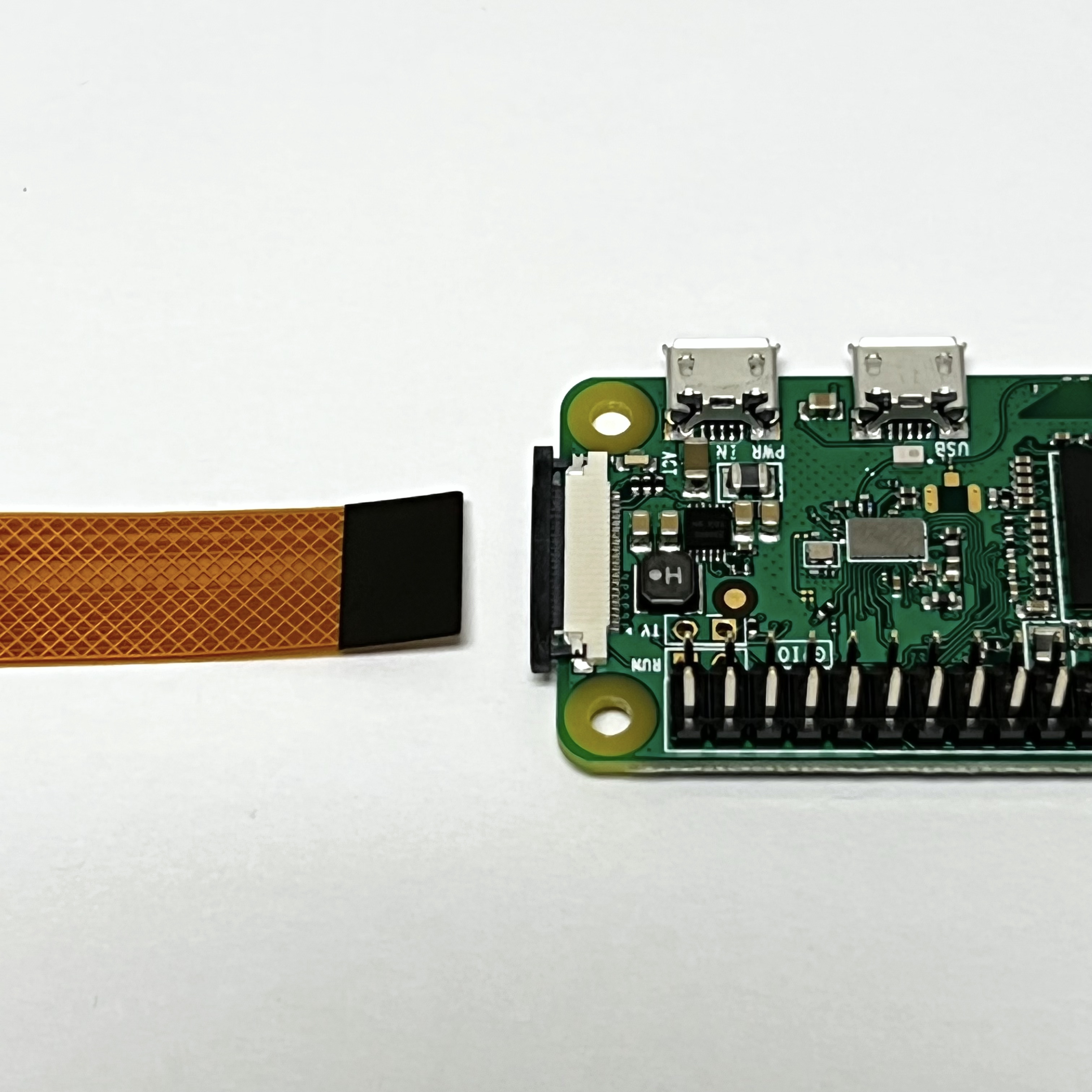
The other end of the Pi Zero Camera Cable connects to the Pi Zero WH on the opposite side to the micro SD card slot. Identify the slide lock, in this photo it is the black plastic:
Carefully move the slide lock away from the board, in this photo to the left. Be very very careful - it is very easy to break it. You might need to move it a little on one side, then the other side. It only moves out a few millimeters and does not come completely off. There may be a plastic "blank" in the slot - you can remove it.
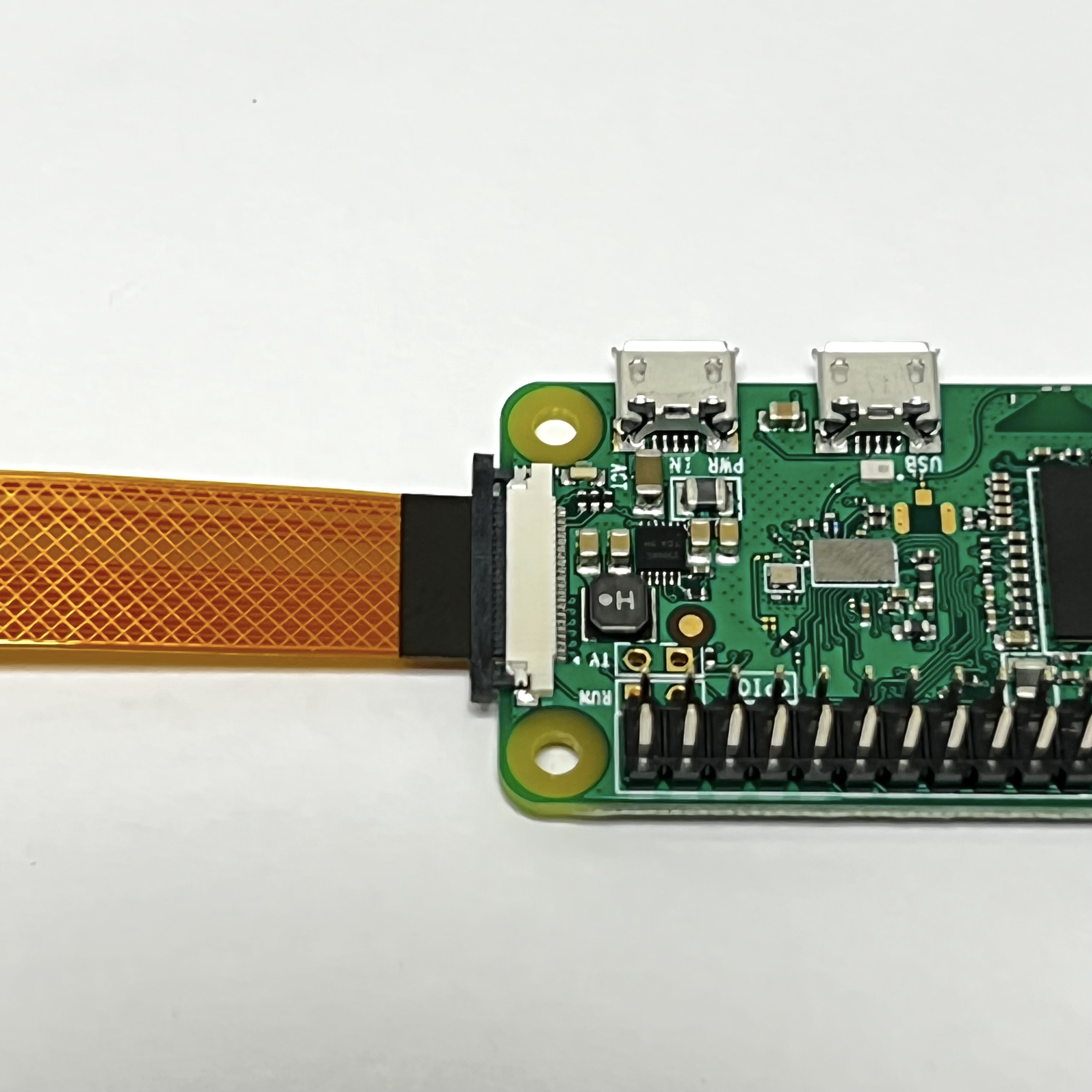
Insert the Pi Zero Camera Cable into the connector. Make sure the metal contacts are facing the PCB, in this photo facing down:
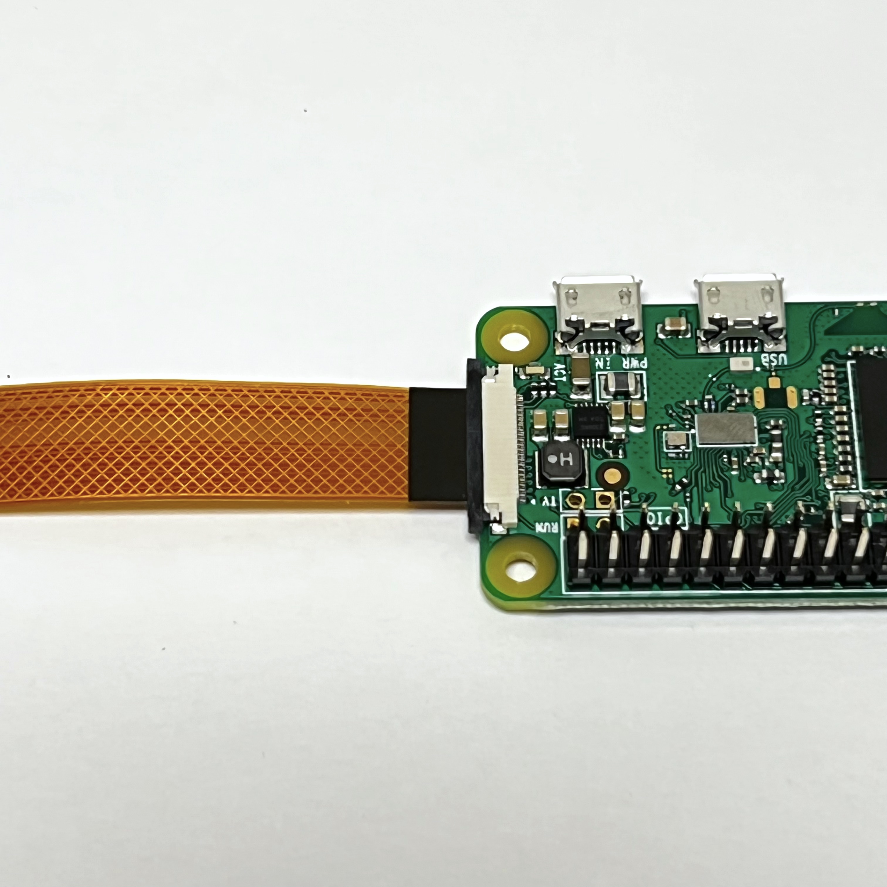
Carefully move the slide lock towards the board (to the left in this photo) to hold the cable securely. Make sure the cable doesn't slide over or get crooked.
Here is what the Pi Zero W and the Pi Camera look like:
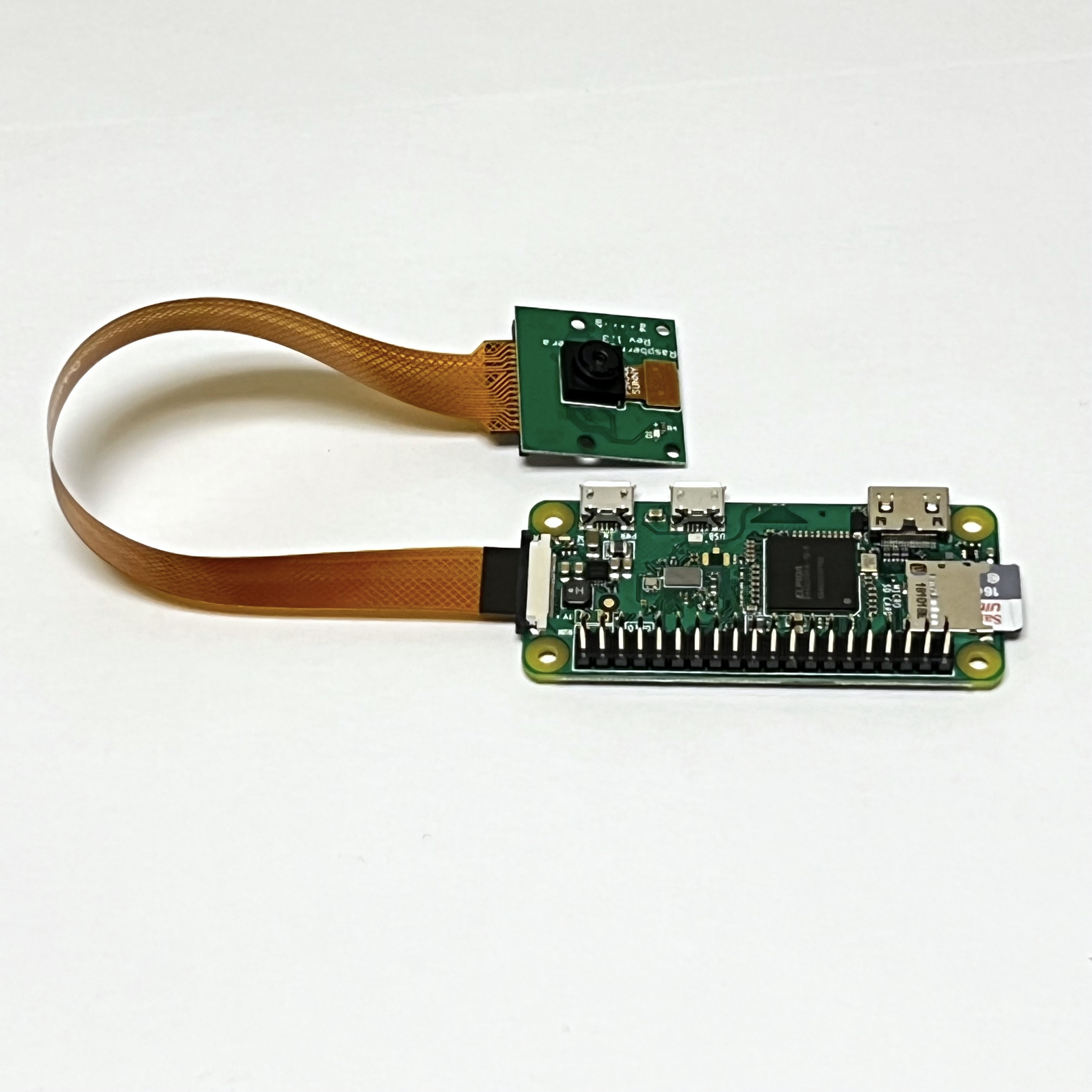
Note that the LED on the Pi Camera will blink once when the Pi Zero boots up and whenever it takes a photo.
The next step is to Step 7 Solar Board.