V2 Frame - alanbjohnston/CubeSatSim GitHub Wiki
Step 7b: Frame Print and Partial Assembly
If the images fail to load, download this PDF with all the images. http://cubesatsim.org/pages/beta/V2%20Frame.pdf
In this step, you will 3D print the CubeSatSim frame and partially assemble it.
Frame Print
Here are the v2 Frame STL files: https://github.com/alanbjohnston/CubeSatSim/tree/beta/hardware/frame/v1.3.2
You need to print two of the top/bottom part and one of each side part.
Frame Test Assembly with Solar Panels
In this step, we will do a Frame test assembly and mount some of the Solar Panels on the Frame.
Video
A video of this step is available here.
Note that the video and the photos here show velcro to attach the solar panels, the new recommendation is to use clear double stick tape https://www.amazon.com/dp/B00004Z4BU It is easier to remove with velcro, but with the double stick tape, the solar panels are held more securely.
Here's the frame parts with the ten Solar panels, plastic screws and nuts, and tape/velcro to secure the panels to the frame:
Here's the frame when it is put together:
The 1U frame of the CubeSatSim has solar panels on each face, which are labeled by the Cartesian axes X, Y, and Z. For the sides that face in the direction of the axes (see https://en.wikipedia.org/wiki/Cartesian_coordinate_system#/media/File:Coord_system_CA_0.svg), they are labeled +X, +Y, and +Z. For the sides that face in the opposite direction, they are labeled -X, -Y, and -Z. The CubeSat Design Specification (CDS) standard also has drawings showing the X, Y, and Z sides of a 1U CubeSat https://www.cubesat.org/cds-announcement. Here is a figure from that document:
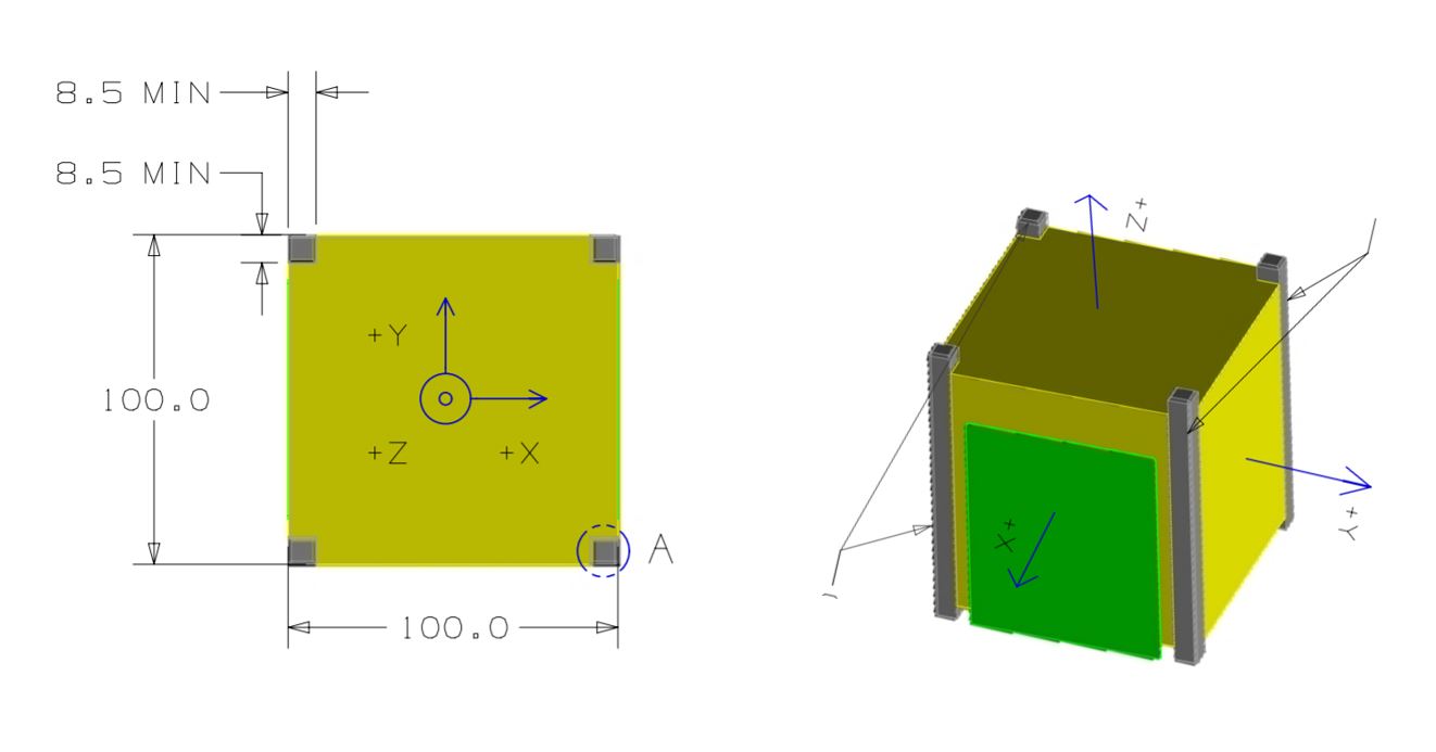
On the CubeSatSim, the +Z side is the top of the CubeSatSim, the +X side has the pushbutton, micro USB connector, and the LEDs. The Main printed circuit board has the axes labeled on it as well.
Start with the top and bottom of the frame (the +Z and -Z sides). One solar panel is mounted on each. Cut four strips of velcro or double stick tape. Peel the backing on one side and stick them on the ribs on the frame:
Peel the backing on the other side and stick the solar panels onto the frame, making sure the JST connectors go to the inside of the frame. Here's how they look when mounted:
You can use a small amount of hot glue to mount the nuts in the top and bottom frame as you attach them. This prevents the screws from falling out when you disassemble the frame later in this step. However, be careful not to get glue in the threads.


Attach the two sides to the frame bottom. Don't tighten the four screws since you are going to be taking the frame a part at the end of this step.
We will start with the -X side. Cut four pieces of velcro and peel one side of the backing and attach to the rows of the frame piece with the camera mount. Don't stick to the frame bottom, just the side frame:
Then peel the other backing and attach the solar panels, again making sure the JST cables go the inside of the frame:
Here's how the panels look if they are removed:
Now do the same for the +X side. Cut four velcro strips and attach to the frame. Then attach the solar panels to the frame:
We will mount the Solar Panels on the +Y and -Y sides when do our Final Assembly.
Remove the screws holding the frame together and separate the four sides.
The frame is now ready for the Final Assembly in V2 Final Integration