V2 Final Integration - alanbjohnston/CubeSatSim GitHub Wiki
Step 8: Final Integration
- If the images fail to load, download this PDF with all the images * http://cubesatsim.org/pages/beta/V2%20Final%20Integration.pdf
If you have completed all three boards, Flat Sat testing, and Stacking, you are ready for Final Integration
You will need:
- Board Stack of three boards, fully tested
- Frame parts and hardware and solar panels, with test fit complete
Video
A video of this step is available.
The Board Stack is now ready to go into the Frame.
Video
Here is a video of the frame assembly
The 1U frame of the CubeSatSim has solar panels on each face, which are labeled by the Cartesian axes X, Y, and Z. For the sides that face in the direction of the axes (see https://en.wikipedia.org/wiki/Cartesian_coordinate_system#/media/File:Coord_system_CA_0.svg), they are labeled +X, +Y, and +Z. For the sides that face in the opposite direction, they are labeled -X, -Y, and -Z. The CubeSat Design Specification (CDS) standard also has drawings showing the X, Y, and Z sides of a 1U CubeSat https://www.cubesat.org/cds-announcement. Here is a figure from that document:
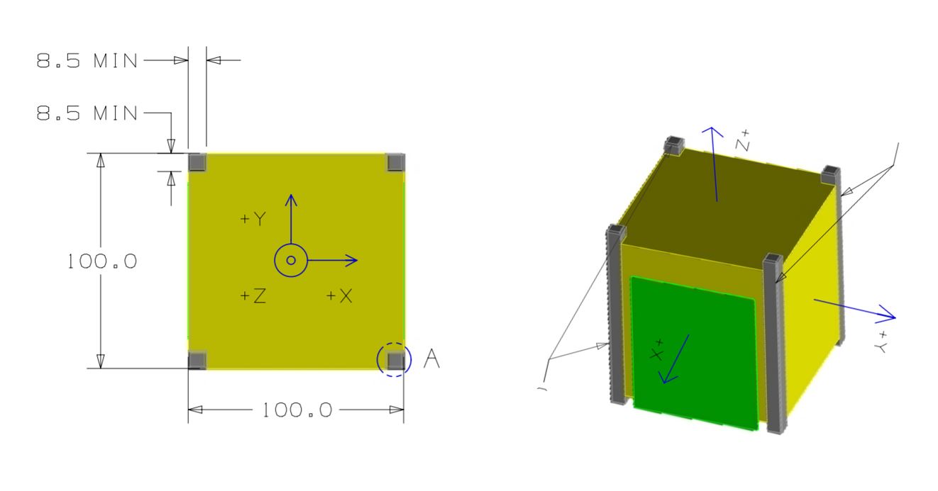
On the CubeSatSim, the +Z side is the top of the CubeSatSim, the +X side has the pushbutton, micro USB connector, and the LEDs. The -X side has the Camera. The STEM Payload printed circuit board has the axes labeled on it as well.
In the Step 6. Solar Panels and Frame you soldered the JST connectors to the solar panels, did a test fit of the frame parts, and mounted the solar panels on the top (+Z), bottom (-Z), and sides (+X and -X).
To build the frame, we will now attach the board stack to the bottom frame, then attach the two sides, then the top.
Four screws mount the bottom of the board stack to the frame bottom. In this photo, the LEDs and other connectors are facing to the left. The Pi Camera ribbon cable is routed as shown here:
Place the -Z frame on top and secure with four screws:
Flip it so the -Z frame is on the bottom. Here's how it looks from the +X side, the side with the LEDs and connectors.
The Pi Camera should face outward on the -X side opposite the LEDs and switches as shown here:
The solar panel JST connectors plug into the Solar board on the top of the stack. Start by plugging in the JST connector from the bottom frame into the -Z solar panel connector on the Solar board.
If you are using the SMA antennas, make sure the SMA coax cables are screwed into the STEM Payload board.
The first frame side to be mounted is the -X side which has the Pi Camera mount. We will mount the Camera using four M2 nylon screws and four M2 nylon nuts:
Here's how the Camera looks from inside and outside the frame when it is mounted.
Carefully stand up the frame, being careful not to stress the Pi Camera ribbon cable and snap into position on the bottom frame. Here's how it looks from the outside:
Here's how it looks from the top:
Secure the -X frame with two nylon screws and two nuts to the -Z bottom frame.
Here is how it looks from the the -X side:
Plug in the two -X solar panel JST cables into the Solar board.
The next frame side to be mounted is the +X side. We will use the frame without the camera mount and two nylon screws and two nylon nuts.
Snap the side frame onto the bottom frame:
Secure the side frame to the bottom frame with the two screws and nuts:
Plug in the two +X JST cables into the Solar board. Here's how it looks from the top with both sides attached and the solar panels plugged in:
Next, we will connect the top frame +Z, but we won't secure it with screws until all the solar panels have been plugged in:
If you are using the SMA antennas, remove the nuts from the coax and insert the coax through the frame, then put the nut on the other side to secure the coax. Plug in the +Z JST cable into the Solar board:
Then, carefully bend the coax so that you can put the top frame in place:
The two SMA antennas can now be screwed on:
Don't secure the top frame to the sides until all the solar panel connections have been made.
Note that the video and the photos here show velcro to attach the solar panels, the new recommendation is to use clear double stick tape https://www.amazon.com/dp/B00004Z4BU It is easier to remove with velcro, but with the double stick tape, the solar panels are held more securely.
Now we will attach the -Y solar panels with three pieces of tape/velcro for each panel:
Stick the tape/velcro to the frame as shown:
Plug the two -Y JST solar panel connections to the Solar board. If you need to, you can raise the top frame since it isn't secured yet:
Stick the two solar panels onto the frame:
Now do the same thing for the +Y solar panels. First stick the tape/velcro to the frame. Then connect the +Y JST connectors to the Solar board. Then stick the panels onto the frame.
Now you can secure the top frame using four plastic screws and four nuts
Here's how it looks:
Remove the RBF switch and verify operation.
Congratulations! Your CubeSatSimm is complete!

You should now test thoroughly your CubeSatSim by running these tests: V2 CubeSatSim Test Plan