v1.1 4. Main Board 2 - alanbjohnston/CubeSatSim GitHub Wiki
We can now start doing some intermediate tests on the board.
You will need these tools:
- Safety glasses (to protect eyes while soldering or trimming leads)
- Soldering iron and solder (I use lead-free solder, but leaded solder is easier to work with)
- Needle nose pliers (to bend leads and hold parts)
- Side cutters (to trim leads)
Other tools that are helpful:
- Blue mounting putty (to hold components in place while soldering)
The first part of this step is testing while the second part continues the assembly
Checklist
The BOM has a sheet "By Steps" which lists the parts needed for each step in order. http://cubesatsim.org/bom If you have a Google account, you can make a copy of this spreadsheet ("File" then "Make a Copy") and check off each part as you install it.
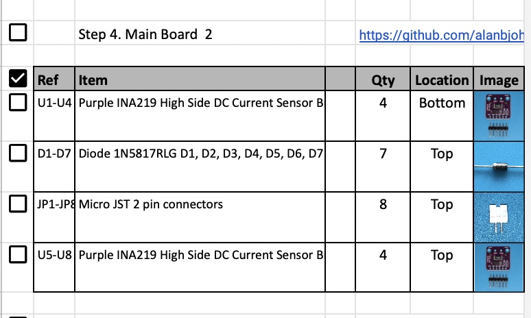
For example, here is the checklist for this step:
Testing
Video
Here is a video of the testing part of this step: https://youtu.be/gZgWQNDQo9U
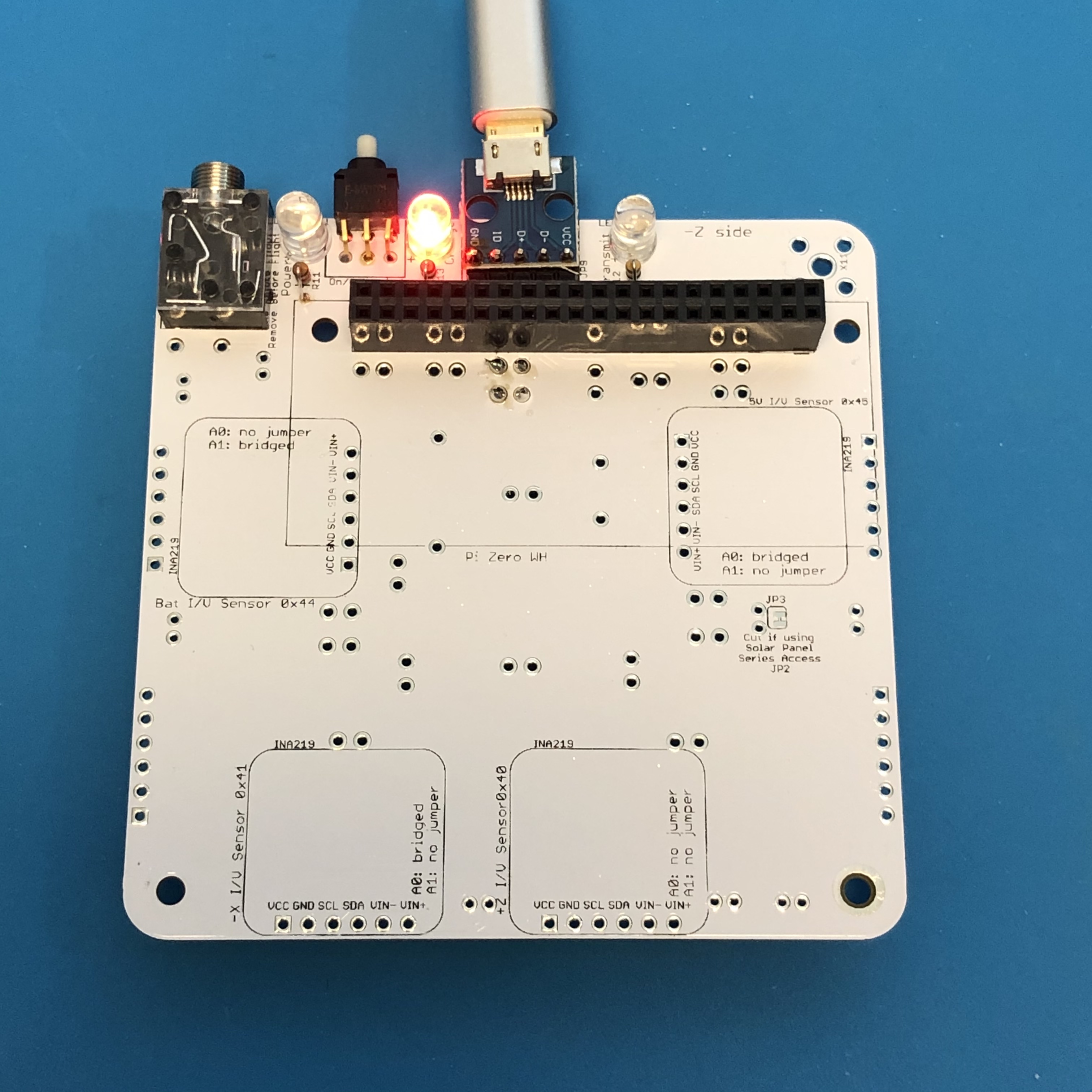
Charge LED Test
For this test, you will need the micro USB charging cable plugged into a computer or a power outlet to supply power. When the charging cable is plugged into the Main board micro USB connector (NOT plugged into the Pi micro USB!), the red Charge LED will illuminate.
If it doesn't illuminate, check the red LED LED3 polarity, resistor R13, micro USB connector, or your USB power cable.
Pi Blink Test
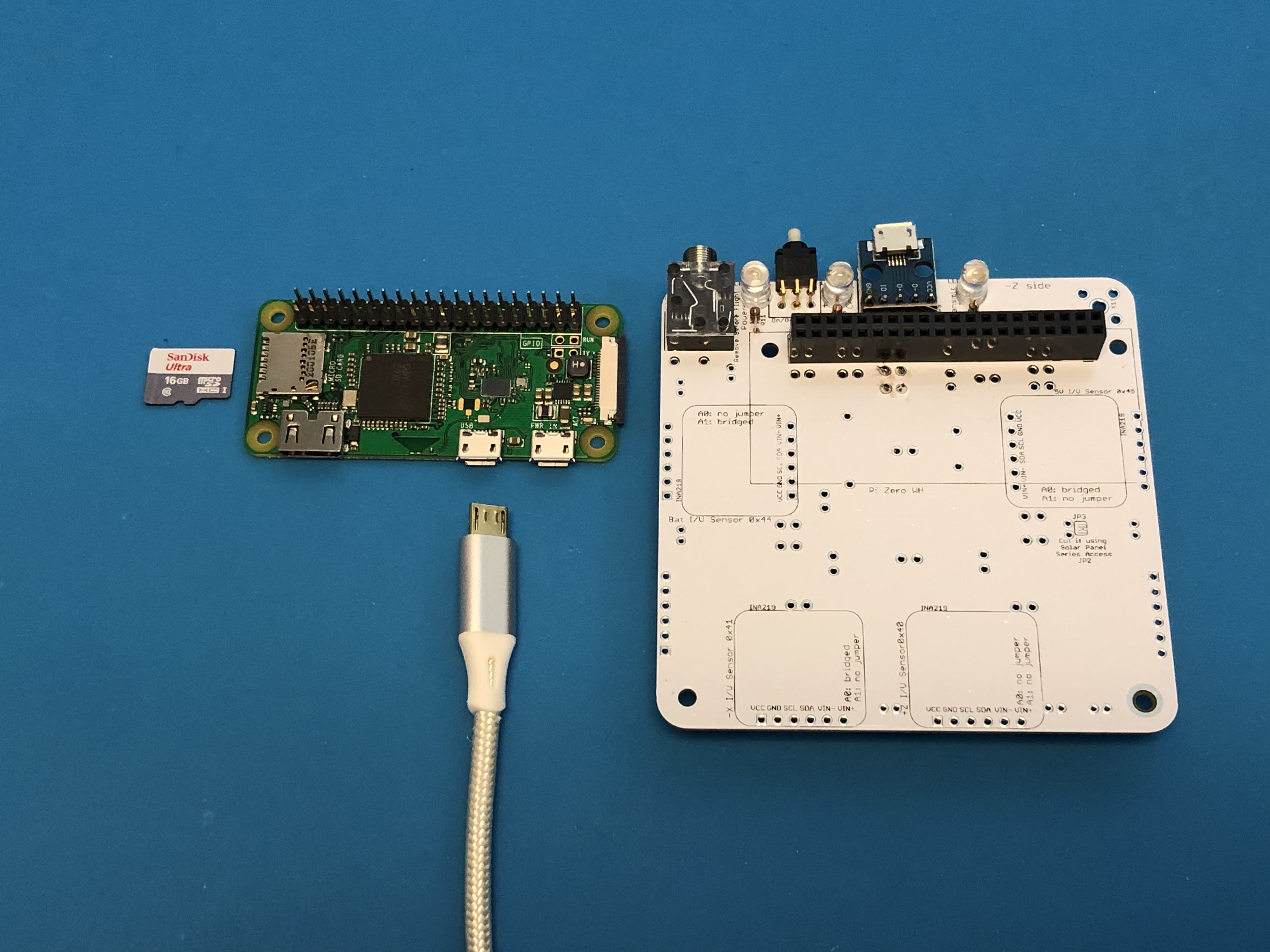
For the rest of these tests, you will need your Raspberry Pi Zero W or Pi Zero, a micro SD card with the CubeSatSim software installed (see the Software Install instructions), and the micro USB power cable.
If your Pi Zero W does not have the 2x20 pin header installed, you will need to carefully solder it in. The pins should stick up on the side that has the ICs and the SD card holder.
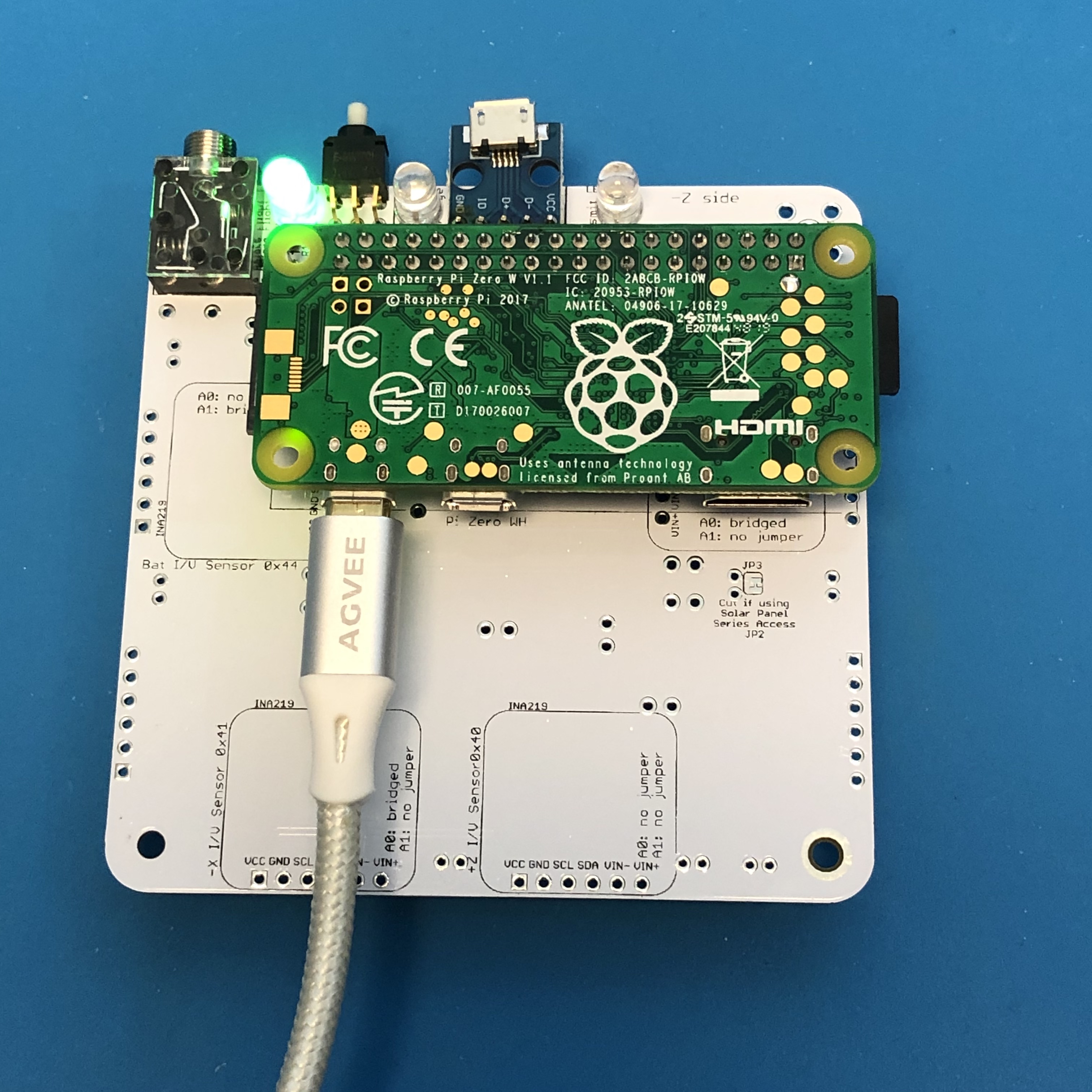
Flip the Pi upside down and plug it into the bottom of the board so that it looks like this:
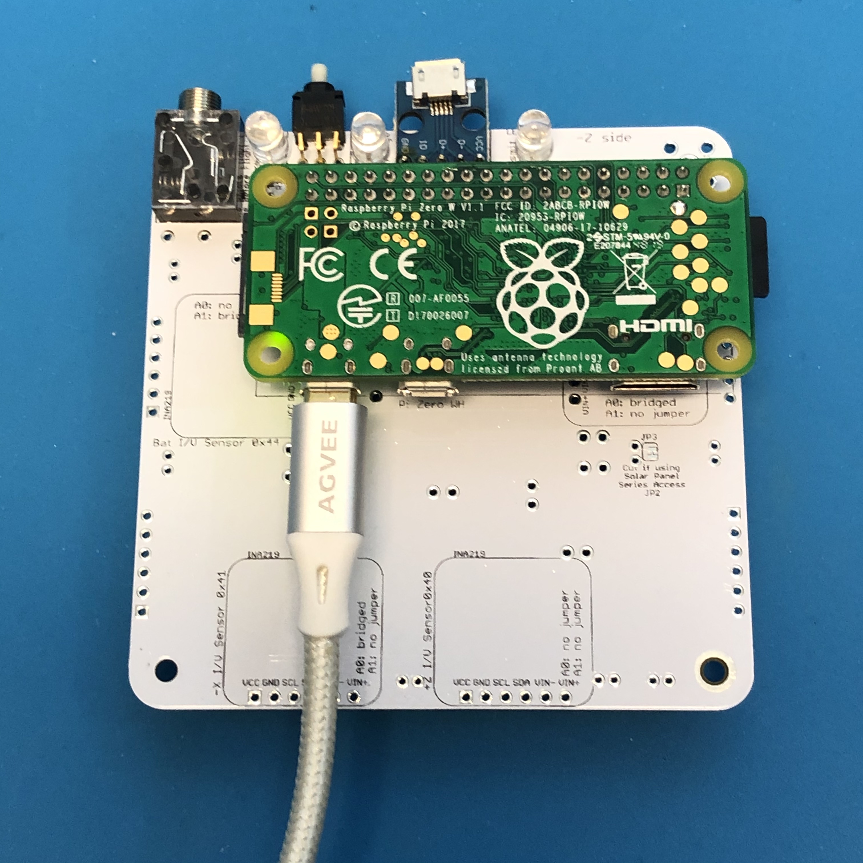
Plug your USB power cable directly via the Pi micro USB port (NOT the Main board micro USB connector like you did to illuminate the red LED). The Pi will turn on and the tiny green LED on the Pi will be on or blinking. Note that the LED is on the top of the Pi Zero W board, but you can see it through the lower left mounting hole, as shown in the photo above.
If you don't see this, make sure you have your micro SD card with the CubeSatSim software installed and the micro USB cable providing power to the Pi.
Power LED Test
With the Pi plugged into the main board and the power cable plugged into the Pi micro USB port, about 30 seconds after booting, the CubeSatSim software will run and turn on the green Power LED.
If the LED doesn't illuminate, it might mean there is a problem with the green LED LED1 or resistor R11 or that the CubeSatSim software isn't running.
Transmit LED Test
With the Pi plugged into the main board and the power cable plugged into the Pi micro USB port, after booting, the CubeSatSim software will run. When the CubeSatSim is transmitting, the blue Transmit LED will be illuminated, occasionally blinking. This indicates that the CubeSatSim is transmitting.
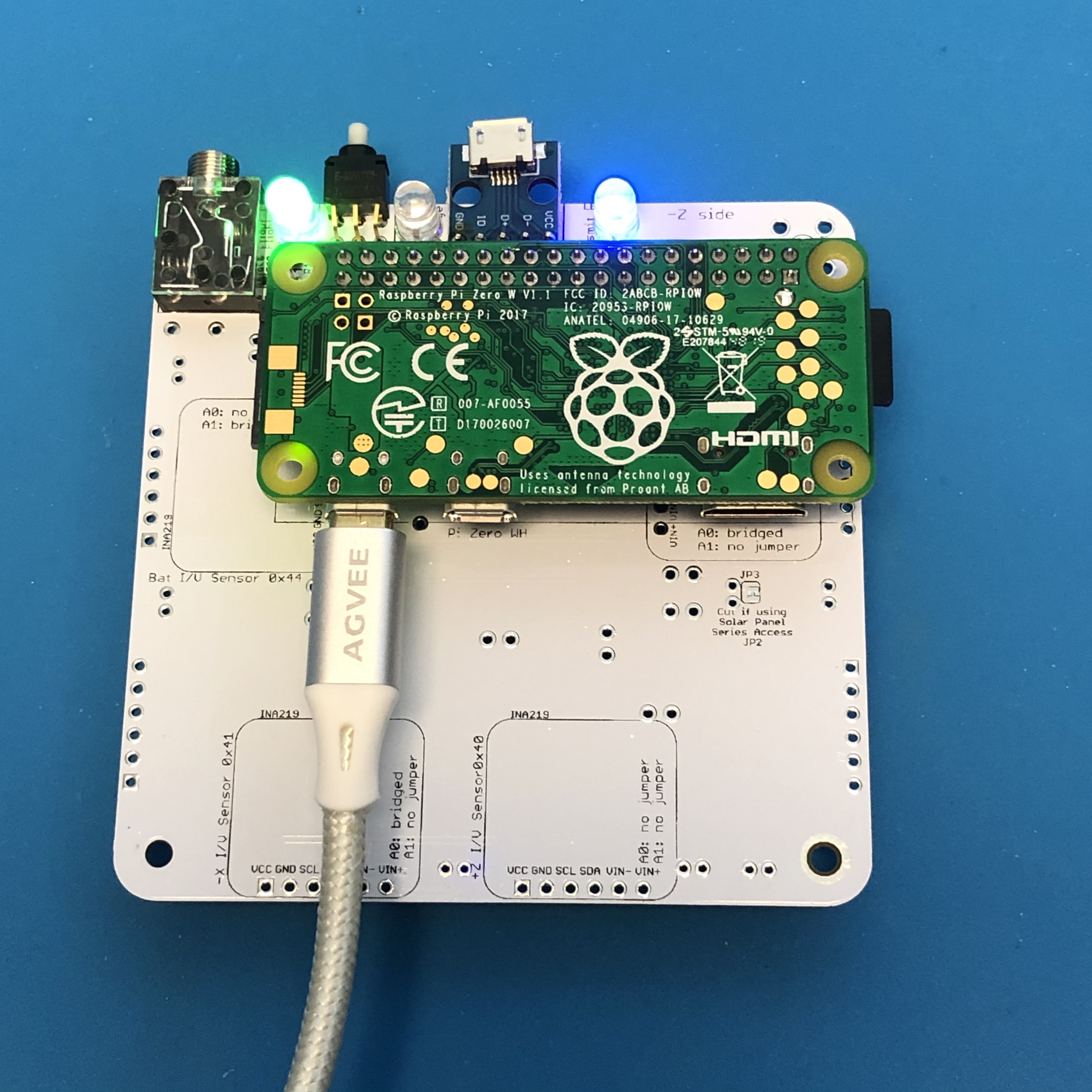
If the blue LED doesn’t illuminate, it might mean there is a problem with the blue LED LED2 or resistor R12 or the CubeSatSim software. If it only illuminates once, it might mean that the Band-Pass Filter is not detected by the presence of resistor R1 or R2 - check this resistor.
Transmit Test
If the blue LED is illuminated or blinking on and off, you can tune your radio or SDR to 434.9 MHz (+/- 15 kHz) to see and hear an FM signal. You don't have an antenna yet, but a close by radio will pick it up. If you have your FoxTelem ground station working (the Ground Station instructions are here), you can try to decode frames in FSK mode.
If your blue Transmit LED is illuminated but you don't see a signal, check your antenna on your radio or SDR, and the gain and frequency on your SDR or radio. Or there may be a problem with the CubeSatSim software, in particular the rpitx library.
Push Button Test
With the Pi plugged into the main board and the power cable plugged into the Pi micro USB port, after booting, the CubeSatSim software will run. When the push button is pressed and held, the green LED should blink rapidly in this sequence: 1 quick blink, 2 quick blinks, 3 quick blinks, 4 quick blinks, 3 slow blinks. Releasing the button after one of the quick blink sequences will put the CubeSatSim in that mode, and the green LED will stop blinking. For example, in this video, the push button is released after the 3 blinks, so the CubeSatSim is in Mode 3. http://countingfromzero.net/amsat/v1/blink.MOV The modes are: 1: APRS, 2: FSK, 3: BPSK, 4: SSTV, 5:CW.
- When pressed and immediately released, the Pi should reboot after about 30 seconds.
- When pressed and held until the green LED starts to blink slowly (see above for the LED blink sequence), the green LED will then blink slowly three times, then the Pi will shutdown (the green Power and blue Transmit LEDs will go out, then the tiny green LED on the Pi will flash rapidly for about 10 seconds then go out). You can release the button as soon as the LED starts blinking slowly. This video shows the button shutting down the Pi: http://countingfromzero.net/amsat/v1/shutdown.MOV After the Pi is shutdown (no LEDs are on or blinking), you can safely disconnect the micro USB power cable and unplug the Pi from the board to continue the build.
- When the Pi is off, pressing and releasing the push button will startup the Pi, as this video shows: http://countingfromzero.net/amsat/v1/power_up.MOV
If the green Power LED doesn’t blink, there might be a problem with the push button switch S1 or with the pi-power-button software.
Continuing the Build
Video
Here is a video of the assembly part of this step: https://youtu.be/9ZKbU2a29TQ
If all your test results are "nominal" (expected results), you can continue your build after shutting down the Pi as described in the Power Button Test (by holding the push button until the green LED blinks slowly then releasing) and unplugging the Pi from the board.
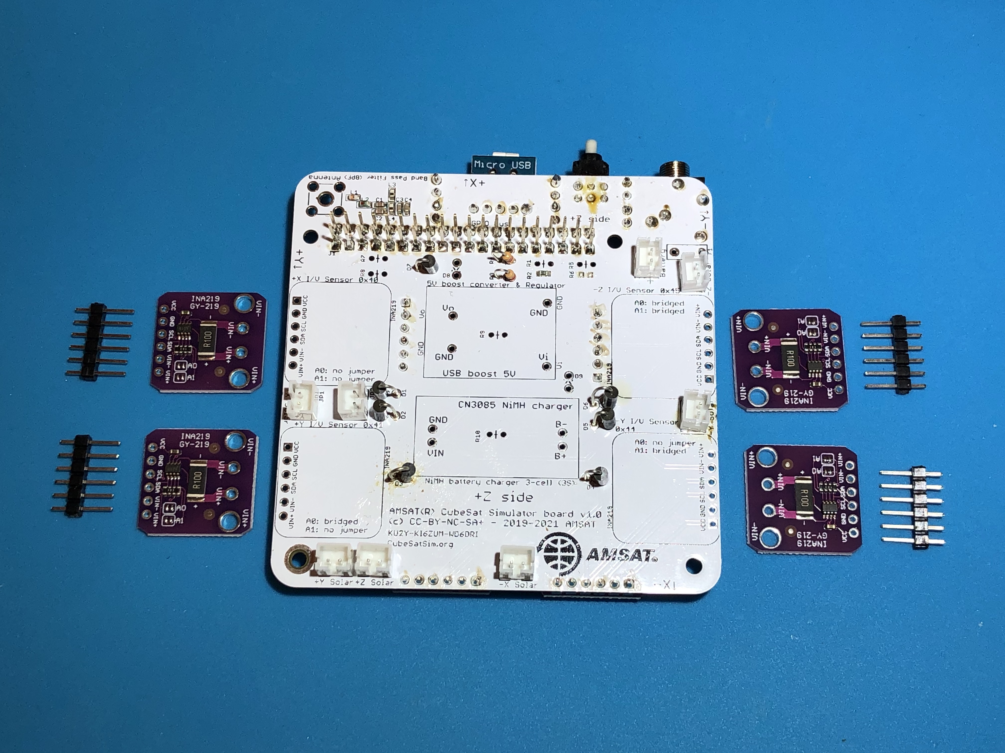
INA219 Install
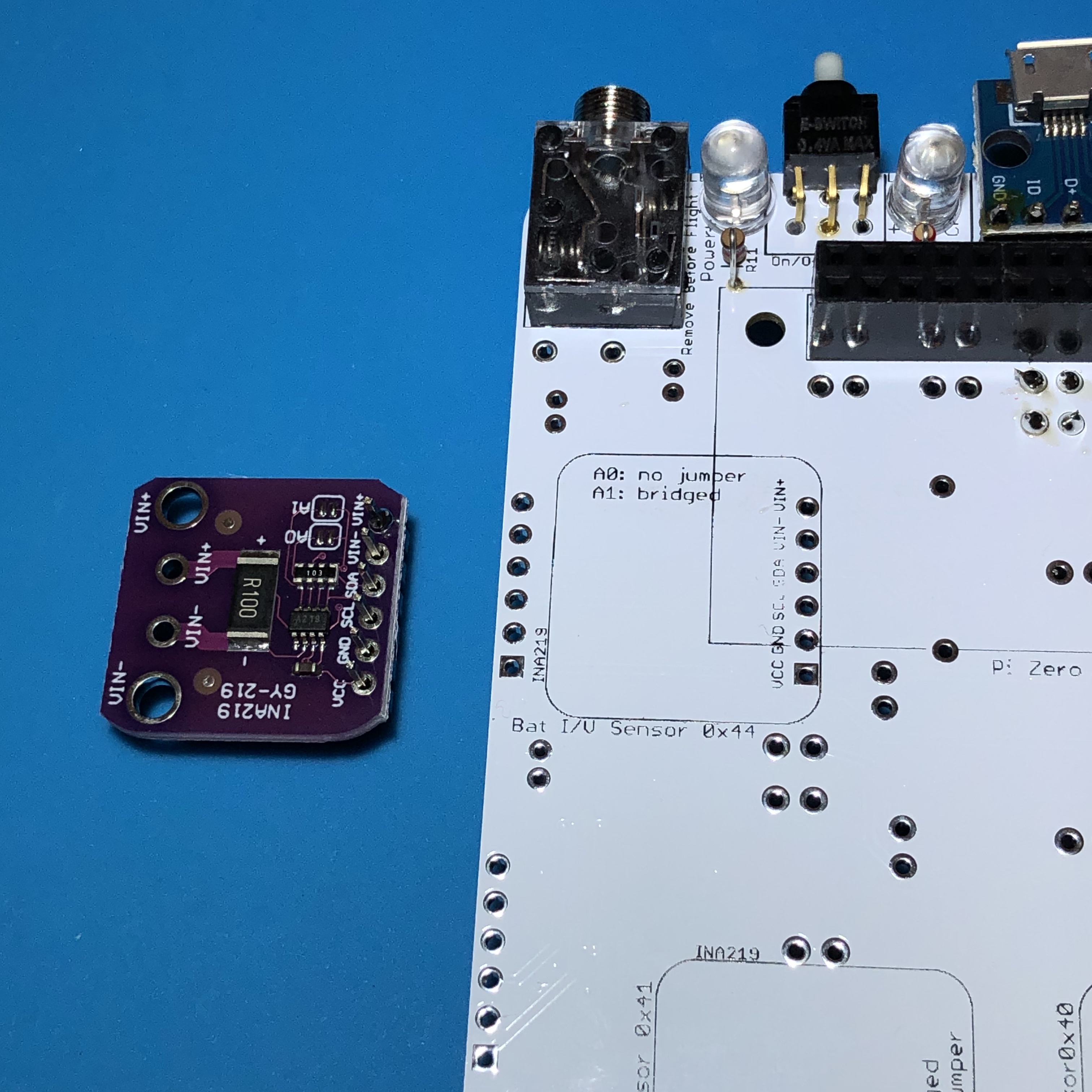
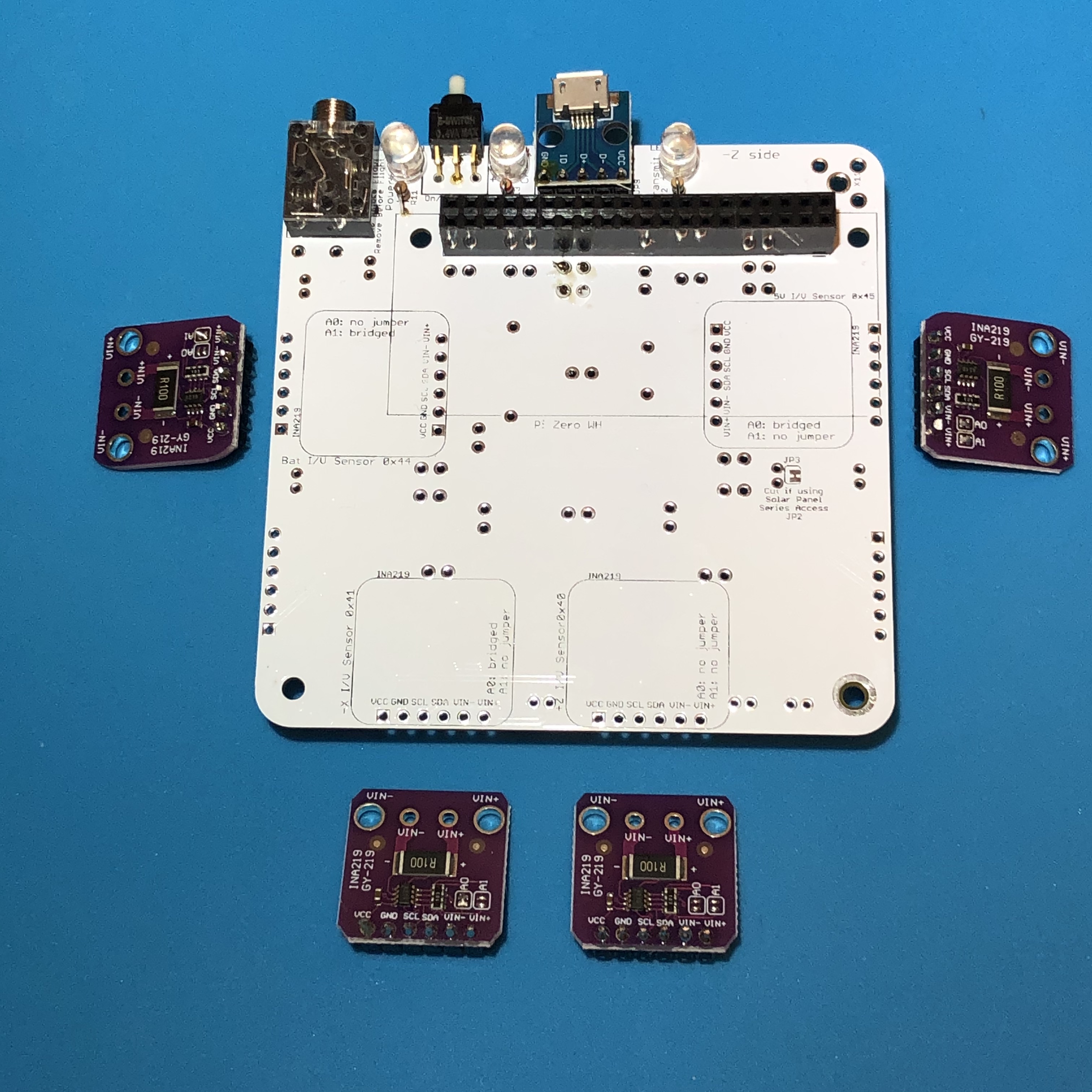
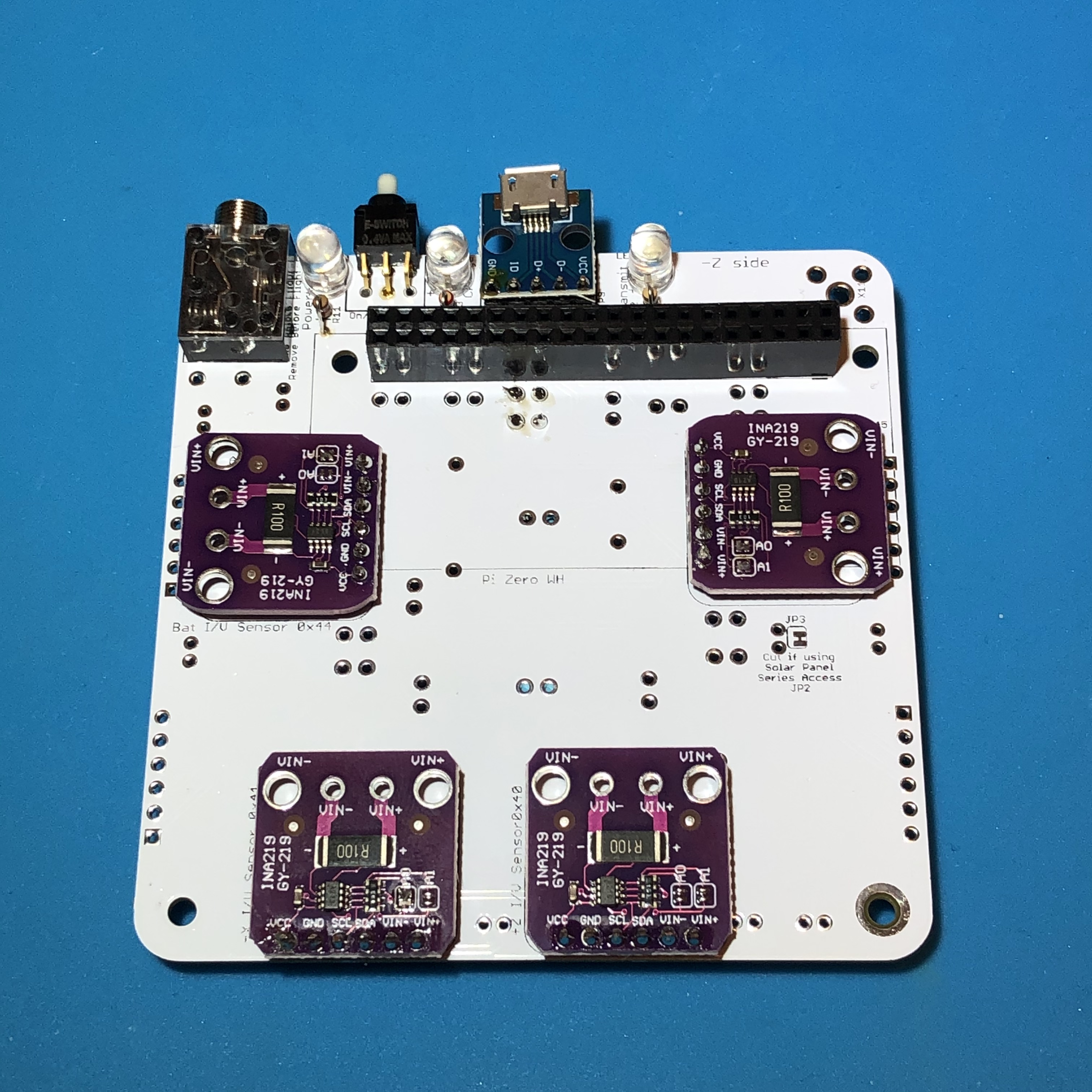
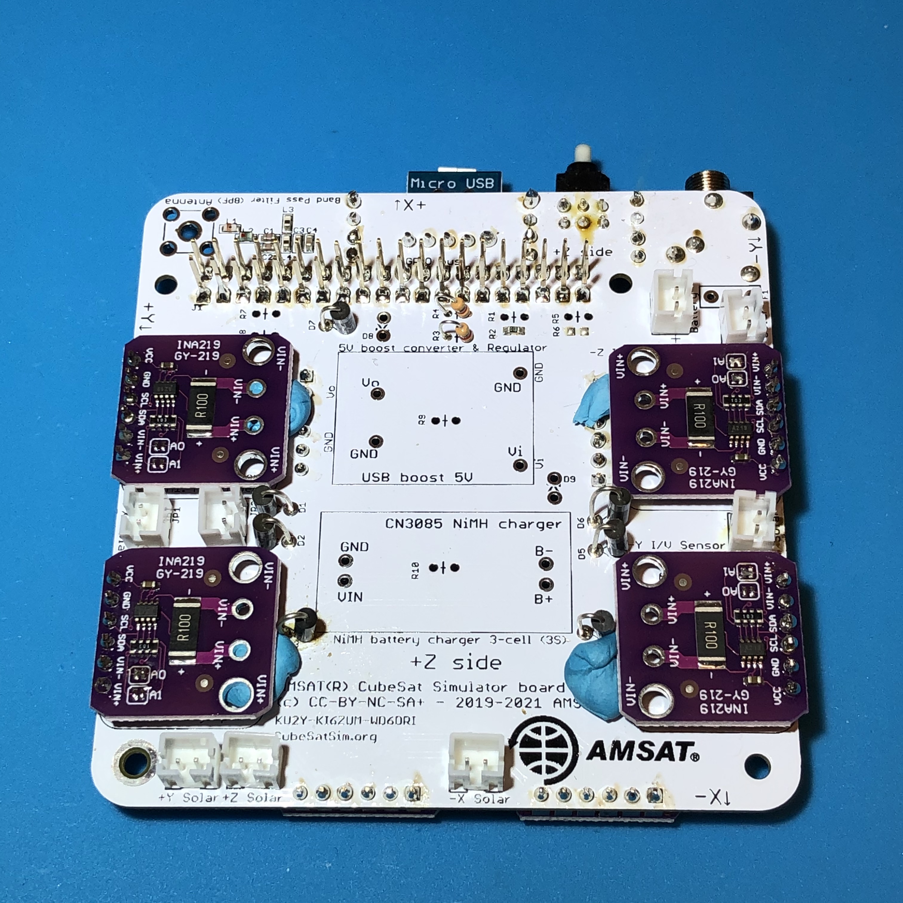
Next you will install four INA219 purple boards on the bottom of the PCB:
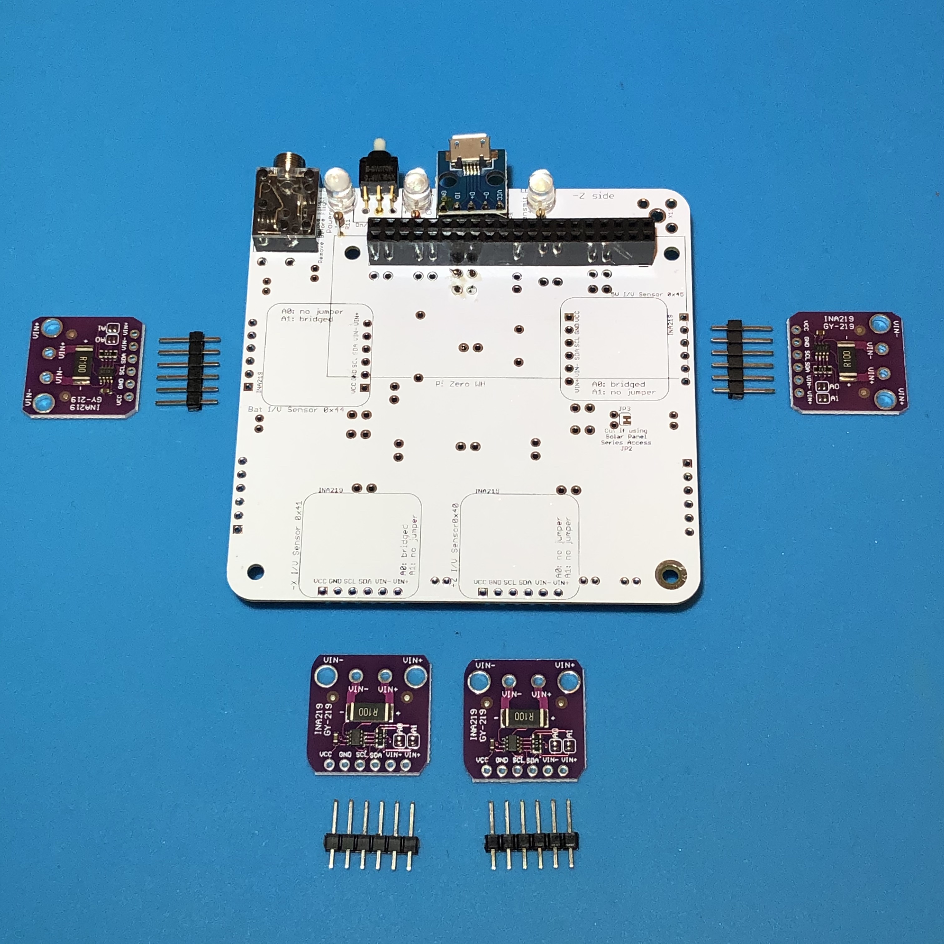
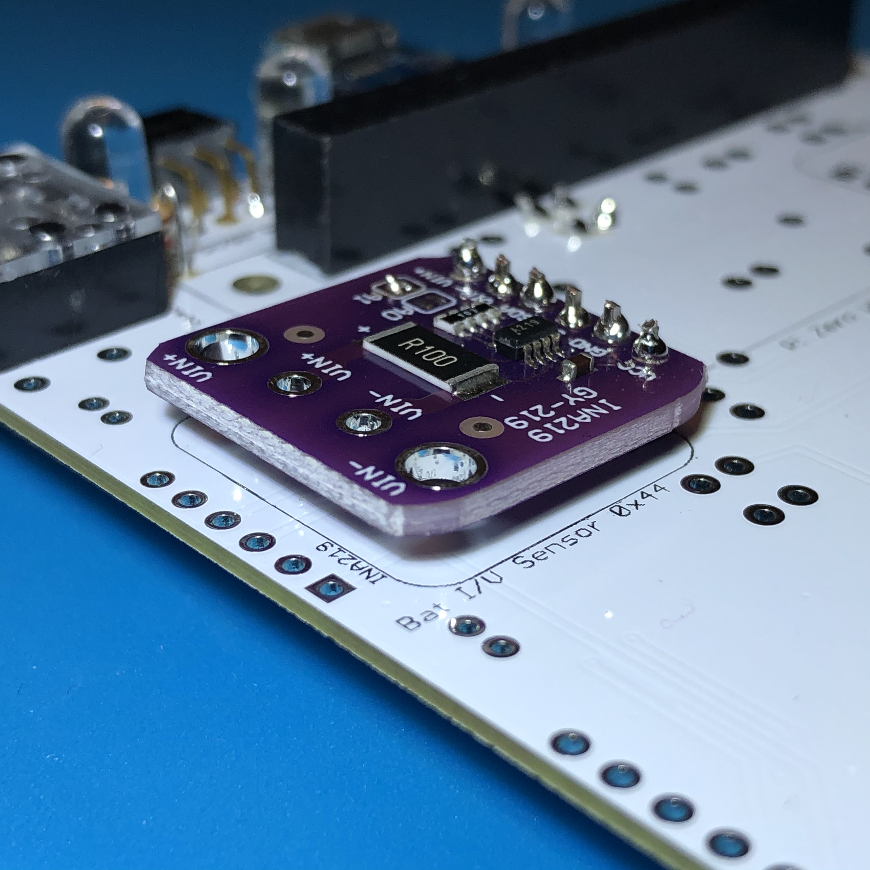
These boards are current and voltage sensors that are on the Pi I2C bus so that the Pi can query them and read the values to include in the housekeeping telemetry decoded in FoxTelem. The design is based on an Adafruit board described here https://learn.adafruit.com/adafruit-ina219-current-sensor-breakout. On the bottom of the PCB, the sensors are on the battery, 5V bus, -X solar panel, and +Z solar panel. Consider the one in the top left for the battery. First insert the 1x6 pin header into the purple board with the longer side of the pins facing up as shown:
Solder one of the pins with the pin header flush against the board and straight. Most INA219 board also come with a screw terminal, but we don't use it in this application.
Check the straightness before soldering the rest of the pins. Cut off the excess pin length from the top.
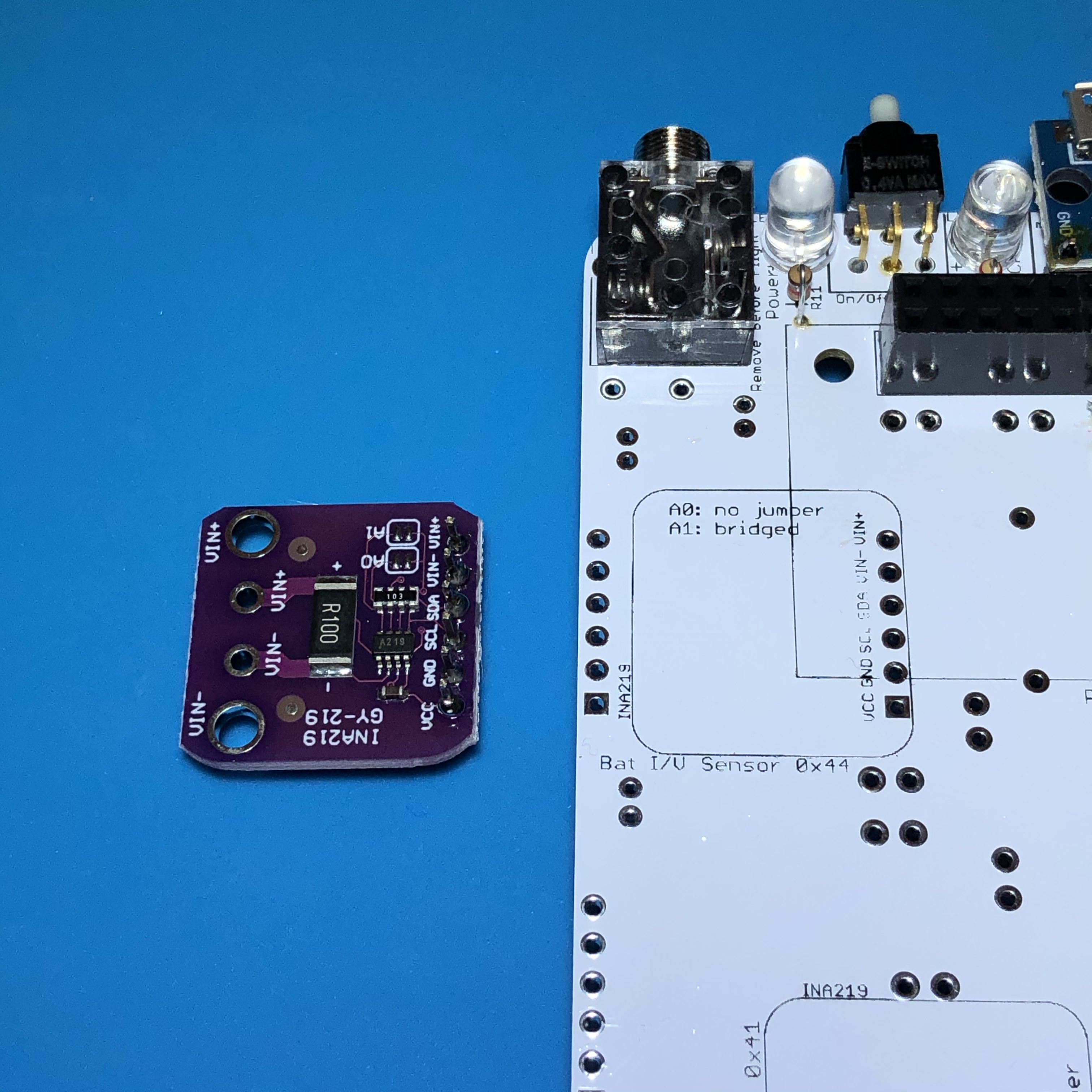
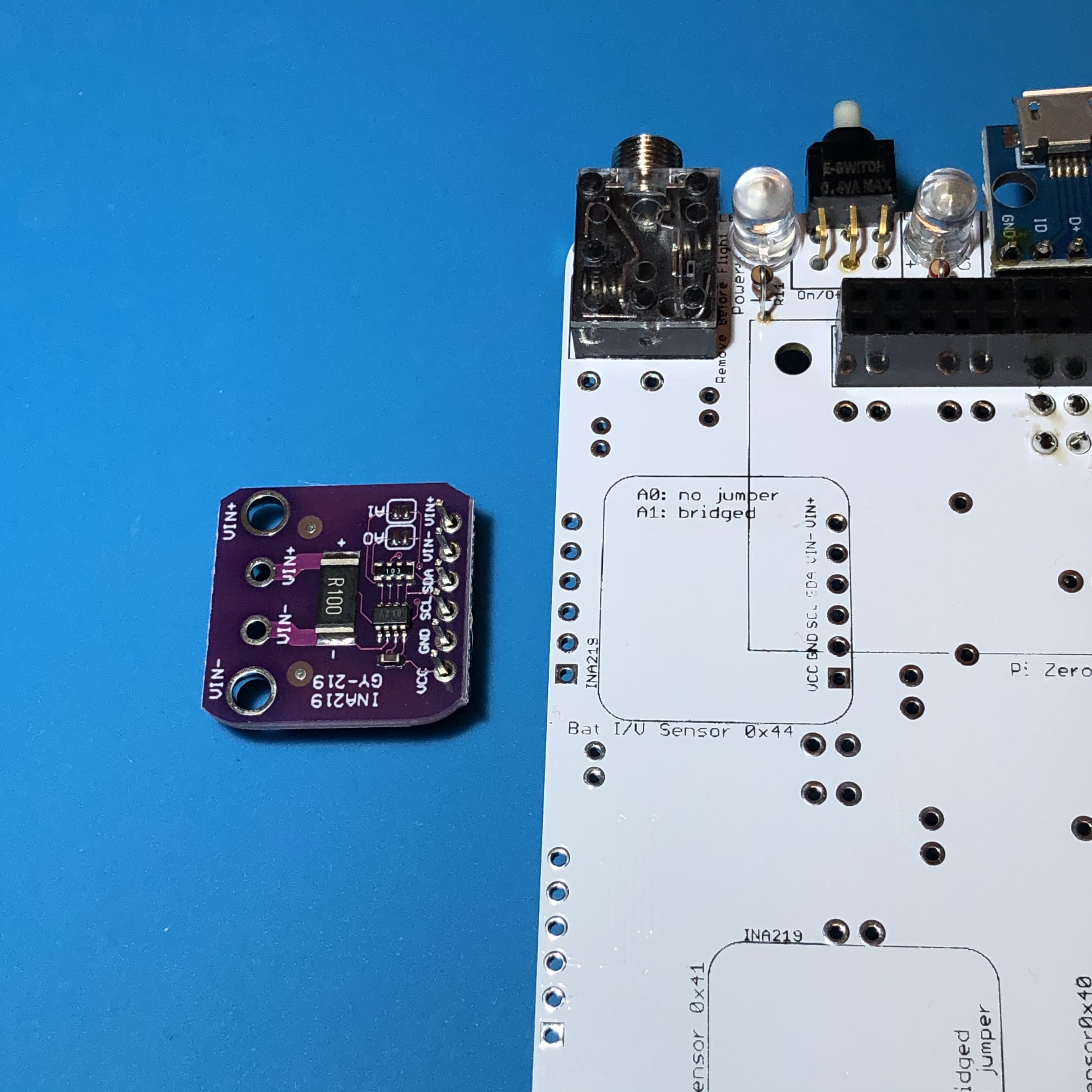
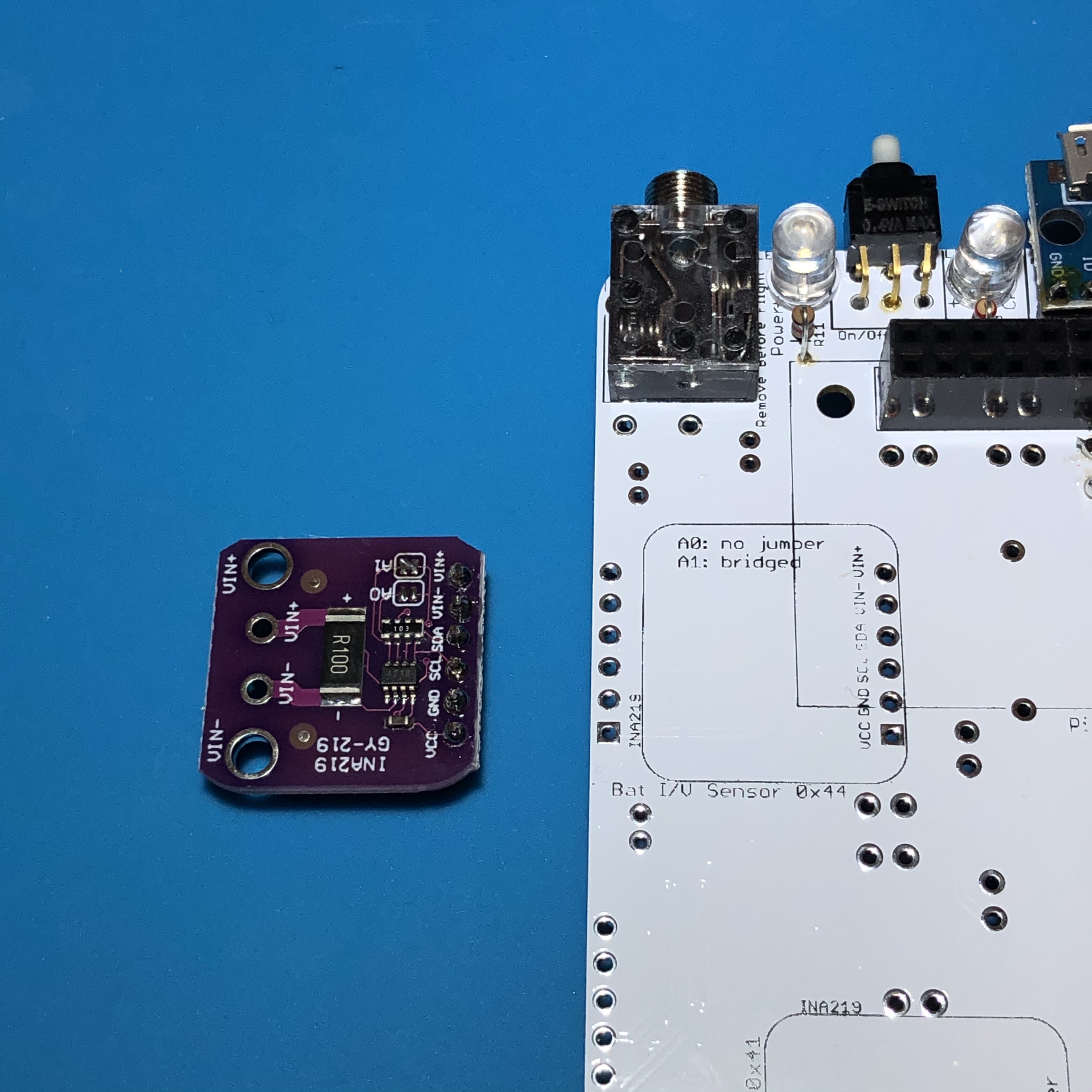
Each sensor needs to have an I2C bus address set by the jumper pads A0 and A1. For this sensor, the address 0x44 is set by having A0 with no jumper and A1 bridged with a small blob of solder (this is written on the PCB for your reference). In this photo, you can see A1 has a solder bridge while A0 does not:
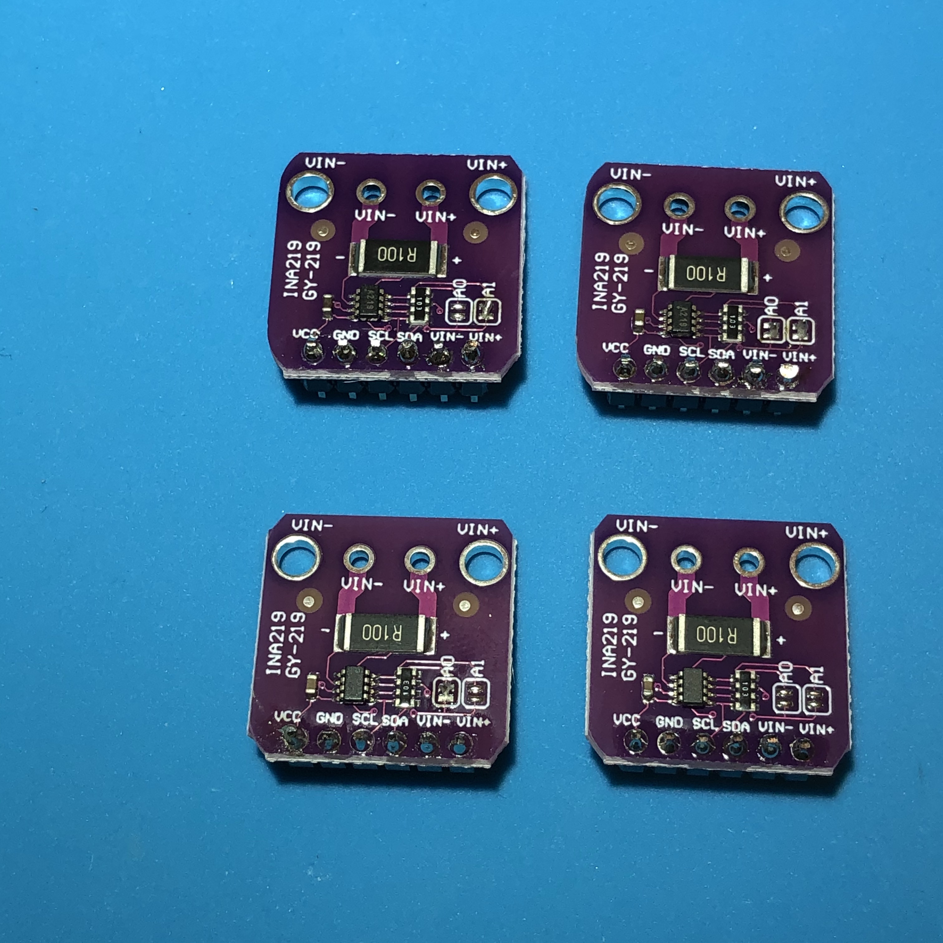
The other three sensors have all the other permutations of jumpers on A0 and A1. This will give four I2C addresses as follows:
- 0x40 (no bridges)
- 0x41 (A0 bridged only)
- 0x44 (A1 bridged only)
- 0x45 (A0 and A1 bridged) as shown:
The four sensors are arranged like this:
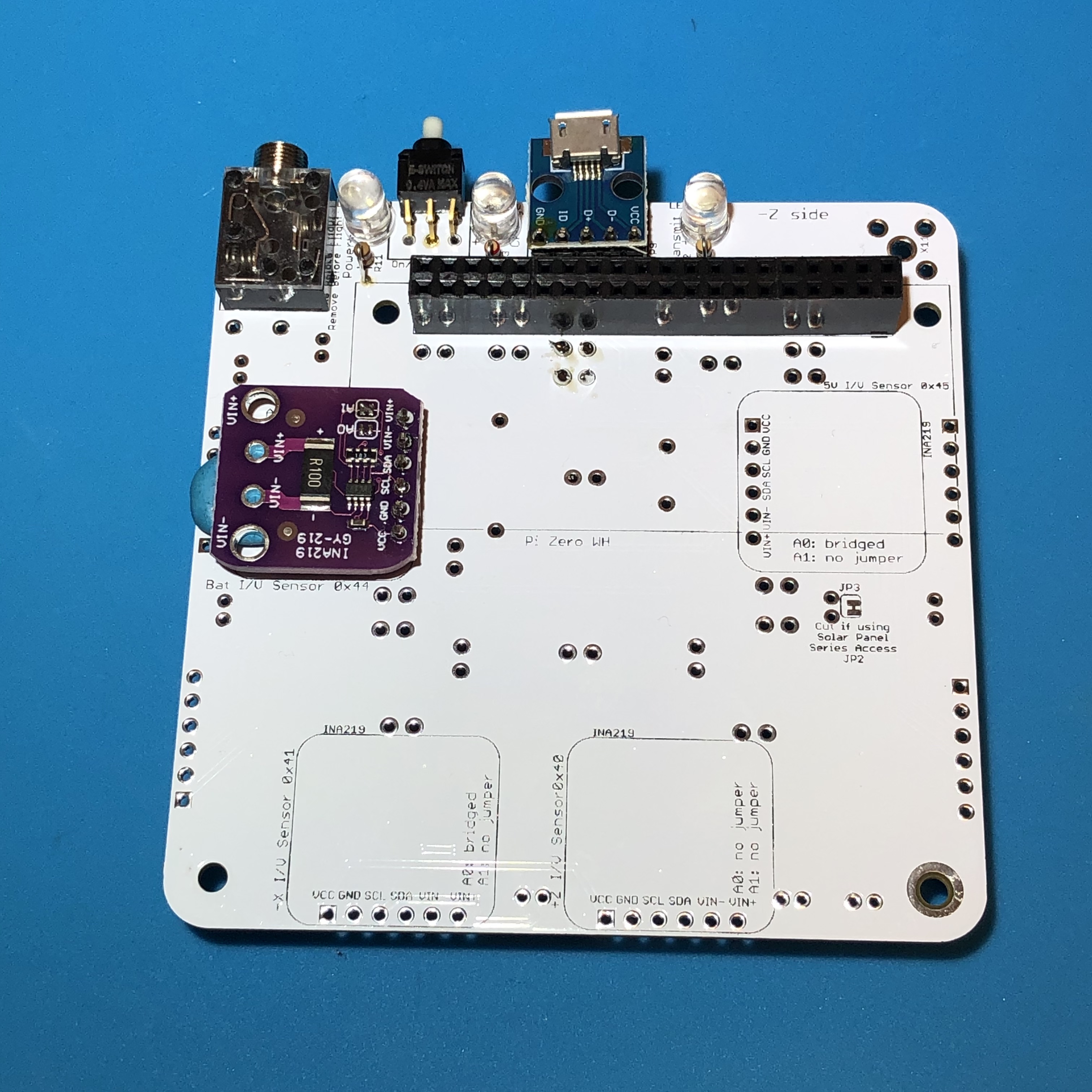
The sensor set to 0x44 is first mounted on the top left using blue mounting putty to keep it level.
Flip the board over and solder the pins on the top of the PCB. When it is soldered, it should look like this on the bottom of the PCB:
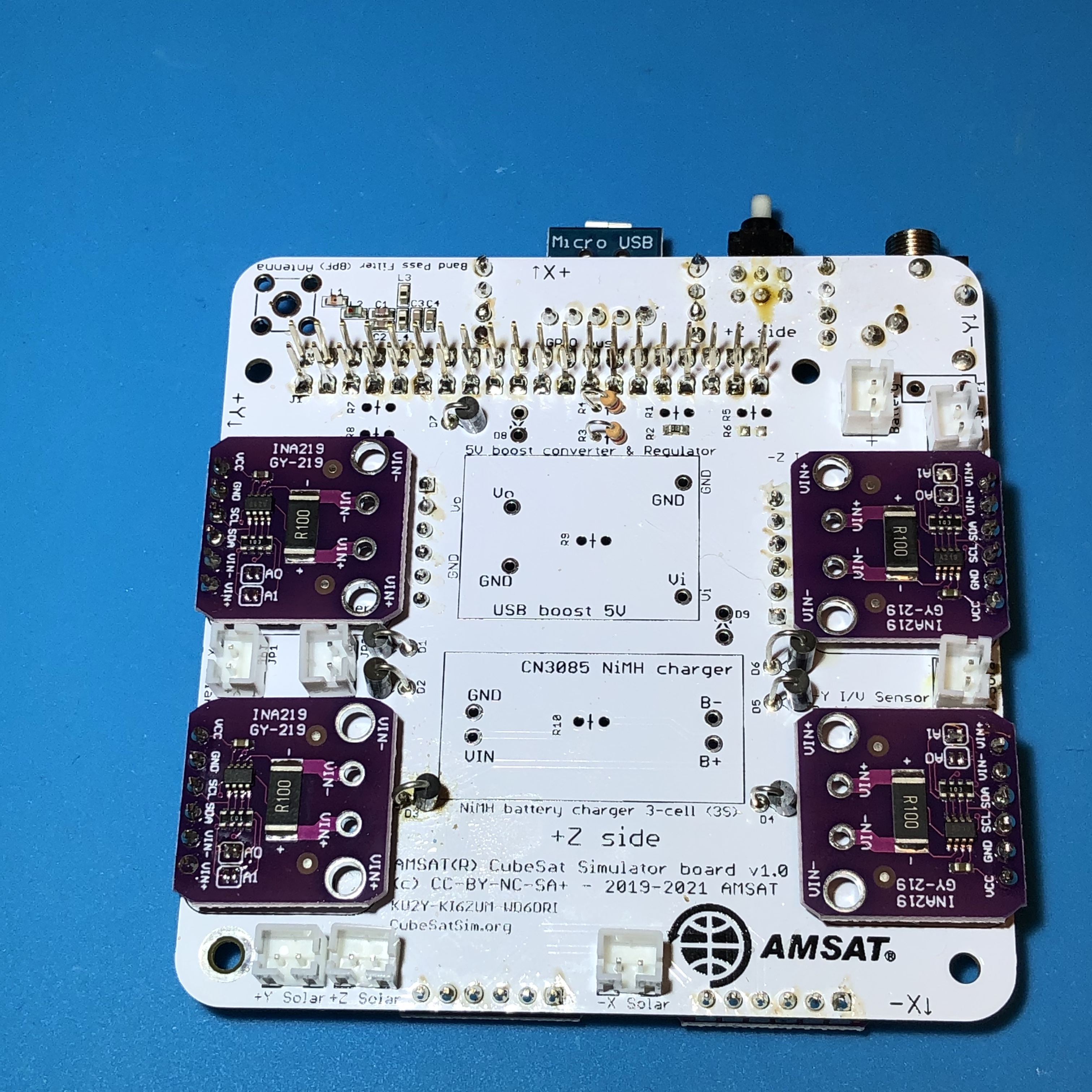
The other three sensors are then mounted:
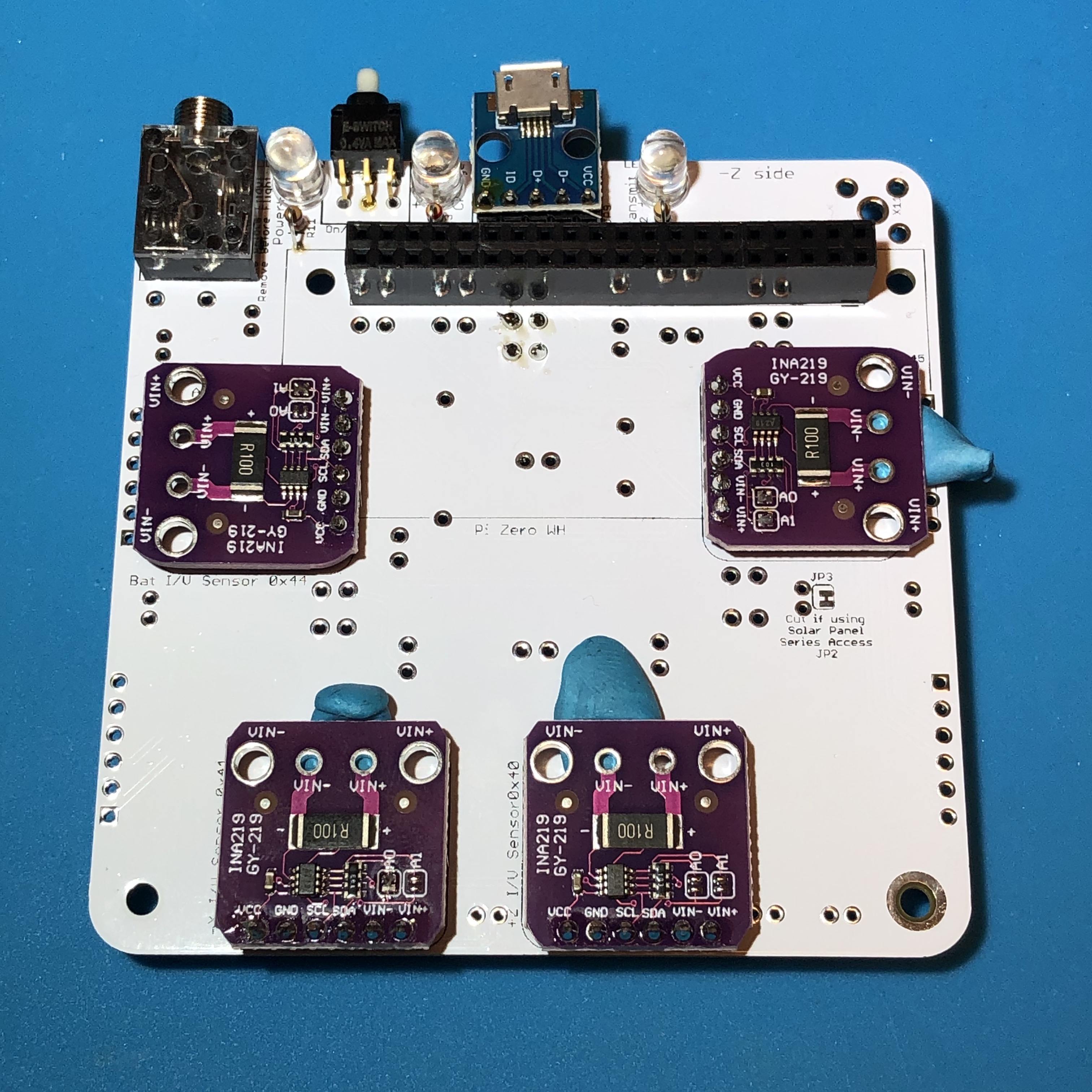
Giving this when they are done:
This completes the bottom of the PCB.
Diode Install
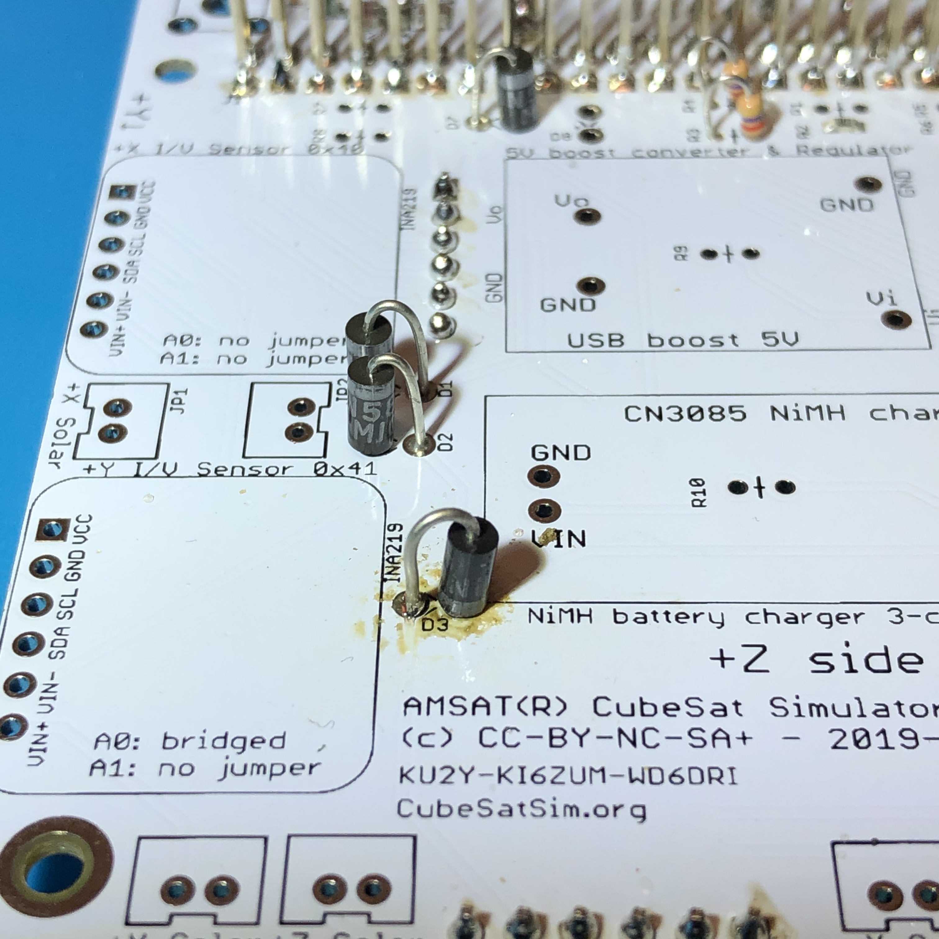
Next, we will mount the 7 1N5817 diodes D1, D2, D3, D4, D5, D6, and D7 on the top of the PCB:
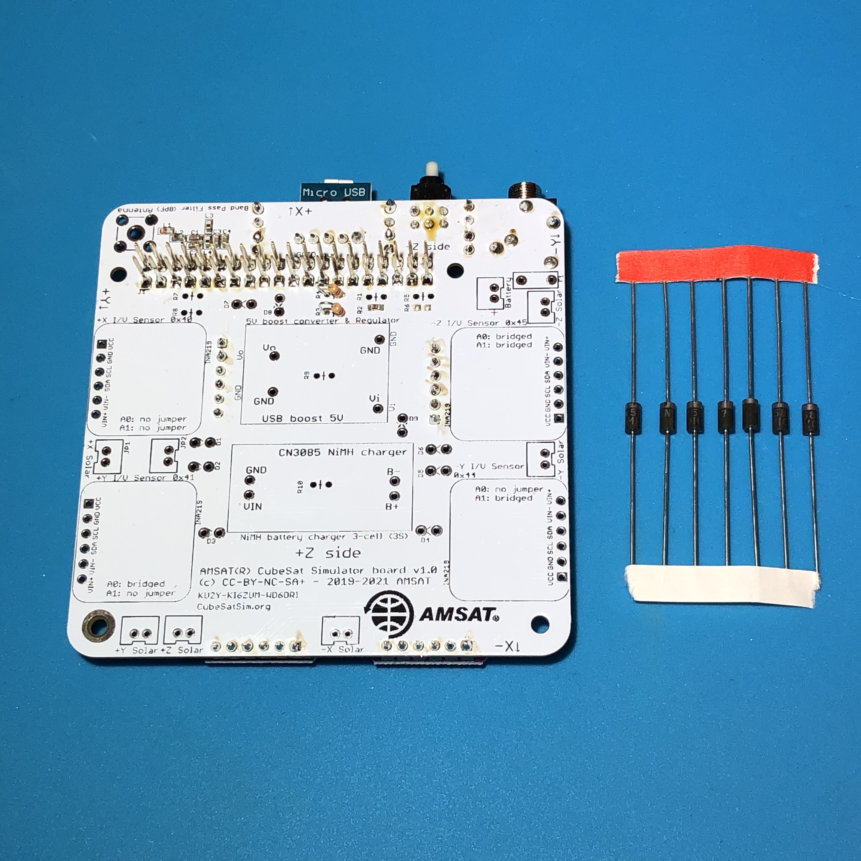
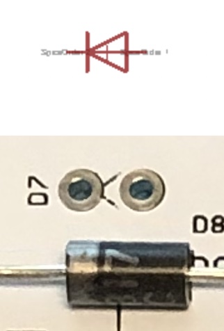
Note that the diodes have a polarity indicated by a grey band on one side. These diodes only allow current to flow from the solar panel to the battery or from the USB charger to the battery and block current from flowing in the other direction. This image shows the diode schematic symbol, the PCB printing, and the marking on the 1N5817 diode.
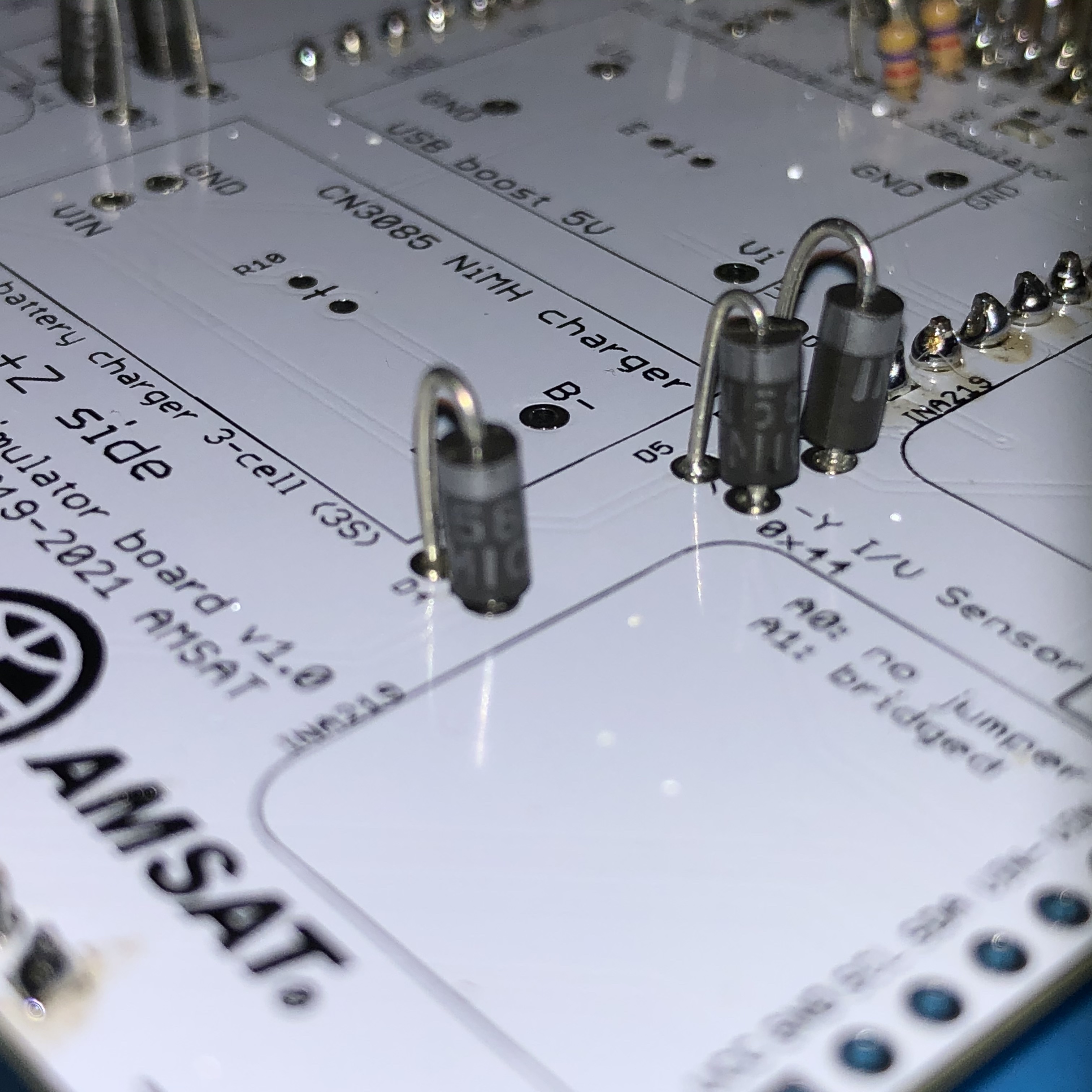
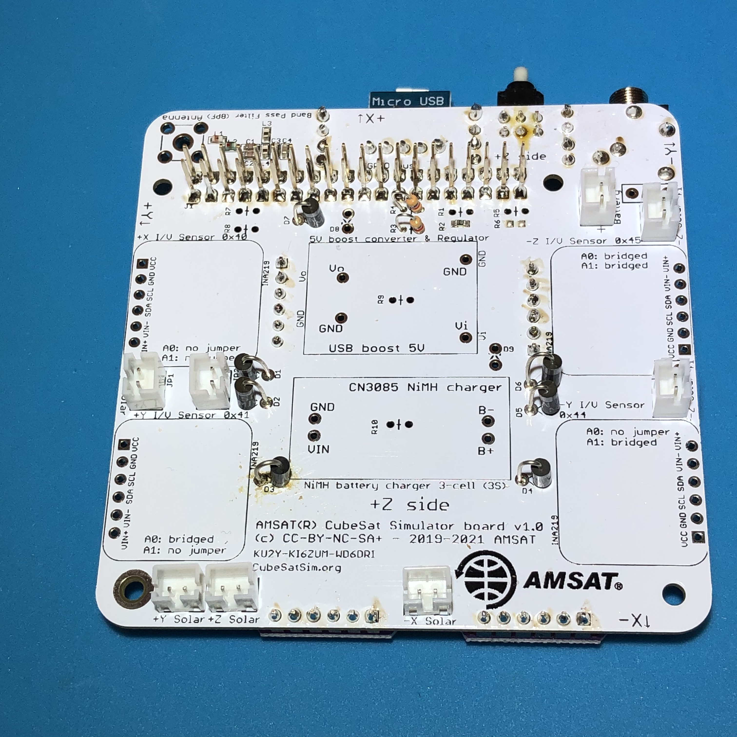
Pay attention to the polarity of the diodes by referring to the photos below. DO NOT install a diode in D8 yet as it is a different type of diode! With all 7 diodes soldered in, the board looks like:
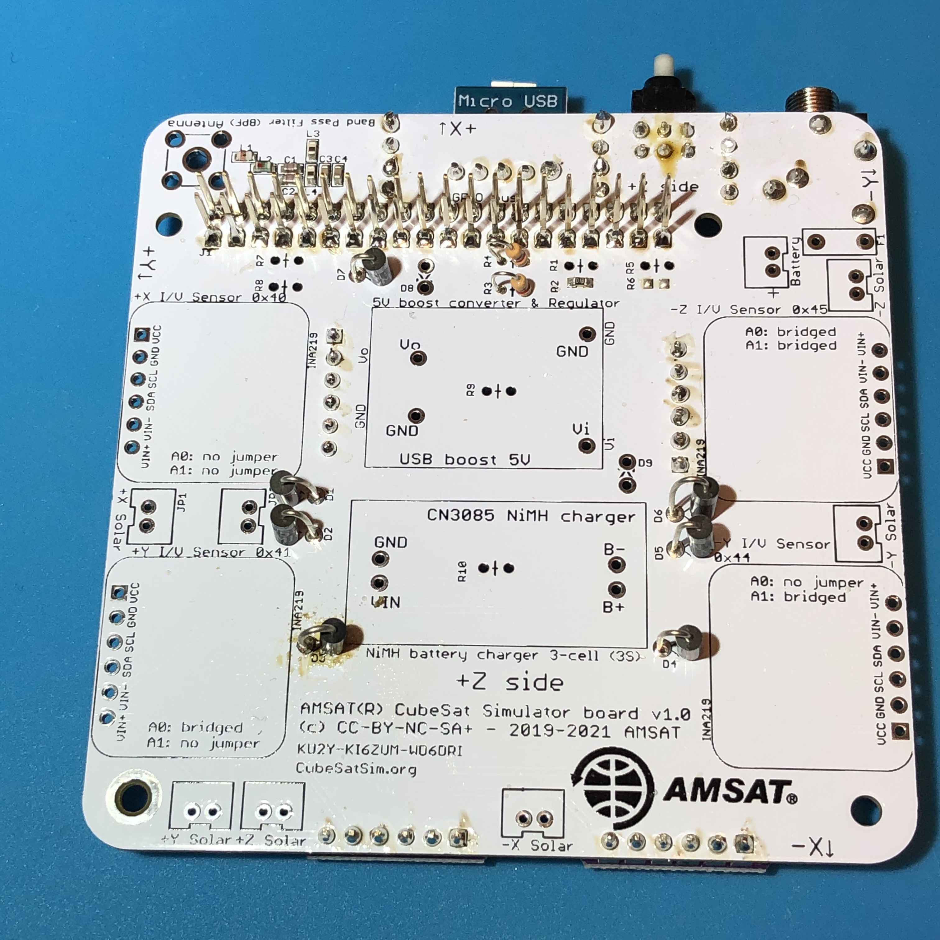
Here are some closeups showing the correct polarity. Note that D3 needs to be mounted upside down compared to the others or it might get in the way of the INA219 board next to it.
JST 2.0 Connectors
Next, solder the 8 JST 2.0 connectors (note: JP5 is optional and can be left off). Pay attention to the polarity as indicated by the notch in the outline that lines up with the slot in the connector.
Then, prepare four more INA219s, setting the four possible addresses as before. Solder them in, paying attention to the jumper A0 and A1 labels on the PCB:
The next step is to build the Battery board.