V2 STEM Payload 2 - alanbjohnston/CubeSatSim GitHub Wiki
Step 4a: Building the CubeSatSim SMT PCB Part 2
These are Part 2 of the instructions for building the STEM Payload Board.
These instructions are for the through hole components after the all the SMT components have been installed and reflowed.
- If images fail to load, download this PDF of the page with all images * http://cubesatsim.org/pages/beta/V2%20STEM%20Payload%202.pdf
STEM Payload Board PCB
These are the instructions for building the STEM Payload board with SMT Components.
Here's the v1.3.2.1 PCB:


Schematic
Here's the schematic for the v1.3.2.1 STEM Payload board for reference:
Video
Here is a video of this step.
Installing the Through-Hole Components
First, we will solder the essential through hole components and then test the board. These components are:
- Red LED (LED5), Green LEDs (LED3) and Blue LEDs (LED4)
- Switch S1
- RBF Switch X1
- Stacking GPIO header J1
- PCB from Part 1 Assembly
First, install the LEDs, being careful not to mix up the colors. The LEDs have a polarity which is indicated by the positive lead being longer than the other lead. In the photo above, the positive lead is indicated by a + which is also marked on the PCB. Also, if you look carefully on the lens, you will see the negative lead has a flattened edge. For all the LEDs, the positive lead is furthest from the edge of the PCB, and the flattened edge is on the side of the edge of the PCB.
Insert the three LEDs on the top of the PCB, being careful not to mix up the colors! Also insert the switch S1 and RBF switch X1.
Flip the PCB over and bend the leads slightly so they are held in position
Solder one pin on each component
Flip the PCB over and make sure the LEDs are fully inserted and straight. If they aren't, apply gentle pressure to the LED lens as you reheat the pin.
Solder the other pin and trim the leads with the side cutters:
Here's how it looks:
Flip the PCB over again to the bottom and insert the stacking GPIO header J1:
Flip it over the to the top again and it should look like this:
Solder only one pin on each side of the header:
Check carefully that it is fully inserted and straight:
Solder the rest of the pins, being careful to use a minimum of solder and don't bridge any pins:
You are now ready for some initial testing!
Initial Testing
Video
Here is a video of this part of the step.
Red LED Test
For this test, you will need the PCB and the USB-C charging cable.
Plug in the USB-C charging cable into the USB-C connector. If the cable is plugged into a power plug or a computer, the red LED should illuminate.
Green and Blue LED Tests
For this test, you will need the PCB, the USB-C charging cable, the Raspberry Pi Zero W with the programmed SD card inserted.
To do these tests, the Raspberry Pi Zero needs to have the software already installed. If your Pi Zero W hasn't been programmed yet, follow theses instructions first V2 Pi Zero Software.
Plug in the Pi Zero W into the bottom of the PCB
Connect the USB-C charging cable to the PCB and to a computer or USB plug to power the board. You will see the red LED immediately illuminate, then the green LED after a few seconds along with the green LED on the Pi Zero underneath. After about 30 seconds, the blue LED should flash a few times then go on and off slowly.
To see the green LED on the Pi Zero, you have to look underneath
When the blue LED is illuminated, the board is transmitting radio signals. If you have a radio or SDR tuned to 434.9 MHz, you will hear the signal.
Next, test out the pushbutton by pressing and holding the pushbutton until it blinks slowly, then release the pushbutton, as shown in this video: https://countingfromzero.net/amsat/BlinkSequence.MOV
After waiting 30 seconds for the Pi Zero to shut down, plug in the RBF switch plug into the board, and all the LEDs should go out except for the red LED.
Unplug the USB-C cable and Pi Zero W to continue soldering.
Assemble the Remove Before Flight (RBF) plug by screwing the black cap onto the 3.5mm plug and inserting the split ring of the RBF tag into the cap:


Finish Through Hole Soldering
Then solder the rest of the through hole components including:
- Female sockets 1x20 J2 and J3
- Female socket 1x8 for the BME280 J5
- BME280 sensor with 1x4 male pin header
- Female socket 1x4 for the MPU6050 J4
- MPU6050 sensor with 1x8 male pin header
- Green LED1 and Blue LED2
- JST connector
- Qwiic adapter board
- Male 1x4 pin header
- Raspberry Pi Pico microcontroller
- micro USB cable, or micro USB adapter for USB-C cable
Start with J2 and J3 the female 1x20 sockets for the Raspberry Pi Pico microcontroller. They need to be installed vertically and with the right spacing, otherwise the Pico won't plug in. Use blue putty and the Pico to help hold the sockets in place as shown:
Flip the PCB upside down and solder one pin on each header:
Look carefully from the side to be sure it is vertical and spaced correctly:
Carefully solder the remaining pins, being careful not to bridge any pins:
Pico Testing
For this test, you will need the PCB, the Raspberry Pi Pico which has been programmed, and a micro USB cable plugged into your computer with the Arduino IDE software installed. If your Pico hasn't been programmed yet, follow theses instructions first V2 Pi Zero Software.
Plug the Pico into the PCB with the micro USB towards the edge of the PCB and connect the micro USB cable
The green LED on the Pico should blink once a second.
The software continuously writes a log file to the serial port. You can view it on a Computer with the Arduino IDE by running the Serial Monitor.
The board selected doesn't really matter. It could be the Raspberry Pi Pico or Pico W if you have it installed. If you don't, you could just select the Arduino Uno board.
You will need to select the Port after you plug the Pico in with the micro USB cable to your computer.
Click on the Serial Monitor icon to open it. You should set the baud rate to 115200 using the drop down menu.
Here's what you will see from the start when the Pico boots up not plugged into anything (the version number may be slightly different):
OK BME280 26.15 991.59 181.94 31.96 MPU6050 -0.07 0.00 0.04 -0.00 -0.06 0.98 XS2 0.0000 0.0000 0.00 MQ 170
Squelch: 1
OK BME280 26.15 991.62 181.65 31.87 MPU6050 -0.07 -0.33 0.04 0.00 -0.06 0.99 XS2 0.0000 0.0000 0.00 MQ 170
Squelch: 1
OK BME280 26.15 991.63 181.56 31.83 MPU6050 0.16 -0.18 0.02 0.00 -0.06 0.99 XS2 0.0000 0.0000 0.00 MQ 170
Squelch: 1
Finish Through Hole Soldering
You will next solder the BME280 and MPU6050 sensors and the female sockets J4 and J5:
Insert J4 and J5 and hold in place with blue putty.
Solder one pin on each and check to make sure it is fully inserted and straight.
For example, from the side:
Solder the remaining pins. Then insert the male pin headers into each socket and place the sensor board on top. The blue MPU6050 sensor will have all the components on top. The purple BME280 will have the sensor module (silver square) on the top. The hole should be on the left side as shown:
Make sure the board sits horizontal, using blue putty to hold it while soldering.
Finally, solder the two LEDs, the JST connector, and the Qwiic connector and the 1x4 male pin header:
First insert the 1x4 male pin header into the top of the PCB:
Solder the four pins on the bottom of the PCB. Then on the top of the PCB, place the red Qwiic connector on top of the pin header and solder the pins.
Here's how the board looks when complete:
Step 8b: Antenna Installation
There are two options for the antenna - either an SMA antenna or a tape measure antenna.
SMA Antennas
To connect antennas using SMA connectors, you just need to solder two SMA connectors onto the STEM Payload board.
This part takes a lot of heat, so make sure your iron is set to high heat. You might also want to apply liquid flux to the pins to help solder it.
Which gives this:
You will connect SMA coax cable and a rubber duck antenna to each SMA connector when you put the frame together.
Tape Measure Dipole Antenna
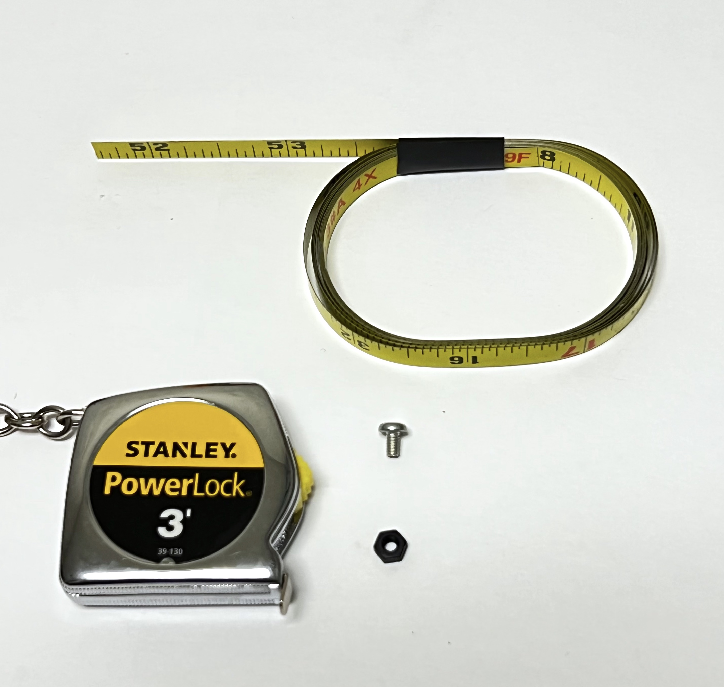
Alternatively, you can make a tape measure dipole or monopole (vertical) using these parts:
-
1/4" Tape measure (3/8" and larger ones work too)
-
Two metal M2.5 screws (nylon will not make electrical contact)
-
Two M2.5 nuts, nylon or metal since it is just a spacer to keep the tape measure from touching the PCB.
Extend all the tape out of the measure before cutting or the remaining tape will retract inside and you will need to break open the case. Be careful of sharp edges, and put electrical tape over the cut edges immediately.
For the dipole antenna, you will need two 1/4 wavelength lengths of tape measure, each with a hole drilled in it. Drilling the hole can be tricky, so drill the hole first, then cut the tape to length. Also, using a punch or small screwdriver to dent the tape in the middle can help prevent the drill from moving around. Also, start with the smallest drill bit you have, ending up with a 3/32" drill bit. It doesn't matter if the hole is slightly off center. Using sand paper or emery cloth, remove the paint from the tape around the hole on the bottom (no numbers) side of the tape measure. Cut to length after you have successfully made the holes, approximately 6.5 inches:
Put the screw through the hole in one of the tape lengths. Then screw the nut onto the screw but don't tighten it all the way.
Press down with the screwdriver as you screw the screw into the PCB and the screw will cut threads into the center hole of the antenna connector as shown. It can be easier to start the screw in the hole without the tape measure at first to begin cutting the threads.
The two tape measure antennas will go through the gap between the solar panels in the frame.
The STEM Payload board is now ready for the next step V2 STEM Payload Testing