V2 STEM Payload Testing - alanbjohnston/CubeSatSim GitHub Wiki
Step 4b: STEM Payload Board Test with Pico, Sensors, Pi Zero, and Ground Station
- If the images fail to load, download this PDF with all the images * http://cubesatsim.org/pages/beta/V2%20STEM%20Payload%20Testing.pdf
For this test, you will need the STEM Payload PCB, the Raspberry Pi Pico which has been programmed, and the Pi Zero with the SD card which has also been programmed. If your Pico or Pi Zero W hasn't been programmed yet, follow theses instructions first V2 Pico Software and V2 Pi Zero Software.
Video
A video of this step is here.
Pico Testing
You can now test that the Raspberry Pi Pico can communicate with the two sensor boards.
You will connect a micro USB to the Pico and to your computer which has the Arduino IDE installed. A green LED on the MPU sensor will illuminate and the LED on the Pico will blink once per second.
In the Arduino software, open the Serial Monitor by clicking on the magnifier icon in the top right of the window. In the Serial Monitor window, make sure 115200 baud is set in the lower right. You should see a response displayed similar to this, updated about once per second:
OK BME280 24.89 1003.96 77.61 21.13 MPU6050 -0.85 -2.48 -1.09 0.19 -0.15 1.02 GPS 0.0 0.0 0.0 TMP 21.0
The OK is the status response. The four numbers after the BME280 are the temperature in Celsius, pressure in hPa, altitude in meters, and humidity in percentage read from the purple BME280 sensor. The six numbers after the MPU6050 are the X, Y, and Z axis angular rotation in degrees per second and the X, Y, and Z axis acceleration in g. If you get a series of zeros after a sensor, it means it was not successfully read by the Pro Micro. The three numbers after XS are extension sensor fields that you can set in the code by setting the Sensor1, Sensor2, and Sensor 3 variables.
If you get all zeros for a sensor, you need to determine if it is a hardware or software problem. Running an I2C bus scanner program will tell you if the sensor can be accessed on the I2C bus.
The blue MPU6050 should be at address 0x68 while the purple BME280 should be at address 0x76. If neither device is present on the I2C bus, make sure resistors R1 and R2 are soldered in and are 4.7k in value. If one sensor shows up but not the other, it might be due to soldering on the sensor pins or due to a bad sensor board.
If both sensors show up on the I2C bus but you get zeros in the Serial Monitor, this indicate a software problem.
Pi Zero Testing
Plug the Pi Zero W into the bottom of the PCB and plug the Pico in the top with the micro USB facing the edge of the PCB. Plug in the USB-C power cable and remove the RBF plug to power it up:
The red LED should immediately illuminate, followed by the green LED, then the blue LED should go on and off. The Pico green LED should blink about once every second.
When the Pi Zero is plugged into the STEM Payload board, the Pi will read the sensor data over the UART and report the data in telemetry.
Push Button Test
When the push button is pressed and held, the green LED should blink rapidly in this sequence: 1 quick blink, 2 quick blinks, 3 quick blinks, 4 quick blinks, 3 slow blinks. Releasing the button after one of the quick blink sequences will put the CubeSatSim in that mode, and the green LED will stop blinking. For example, in this video, the push button is released after the 3 blinks, so the CubeSatSim is in Mode 3. http://countingfromzero.net/amsat/v1/blink.MOV The modes are: 1: APRS, 2: FSK, 3: BPSK, 4: SSTV, 5:CW.
- When pressed and immediately released, the Pi should reboot after about 30 seconds.
- When pressed and held until the green LED starts to blink slowly (see above for the LED blink sequence), the green LED will then blink slowly three times, then the Pi will shutdown (the green Power and blue Transmit LEDs will go out, then the tiny green LED on the Pi will flash rapidly for about 10 seconds then go out). You can release the button as soon as the LED starts blinking slowly. This video shows the button shutting down the Pi: http://countingfromzero.net/amsat/v1/shutdown.MOV After the Pi is shutdown (no LEDs are on or blinking), you can safely insert the Remove Before Flight plug to power the CubeSatSim off.
If the green Power LED doesn’t blink, there might be a problem with the push button switch S1 or with the pi-power-button software.
If you don't hear anything or see anything for the FM modes (APRS, SSTV, and CW), try listening on 450.000 MHz for the signal. If you hear the signal there, it means the FM Transceiver module hasn't had its frequency set to 434.9 MHz by the Pi Zero software. Try powering down everything and then powering up again.
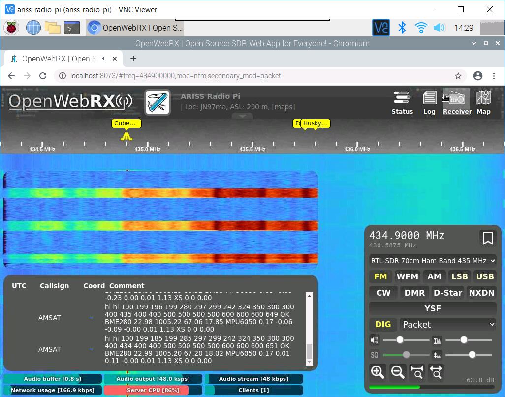
Put the CubeSatSim into APRS mode by pressing and holding the push button until the green power LED blinks once, then release it. Or, you can log into the Pi Zero and enter the command CubeSatSim/config -a then return. The CubeSatSim will reboot and start up in APRS mode. Set your Ground Station to decode APRS, either by using Direwolf or the Web SDR set to Digital Packet mode. You should decode an APRS packet every 30 seconds, and you should see the sensor string added to the end of the data.
Put the CubeSatSim into FSK mode by pressing and holding the push button until the green power LED blinks twice, then release it. Or, you can log into the Pi Zero and enter the command CubeSatSim/config -f then return. The CubeSatSim will reboot and start up in FSK mode.
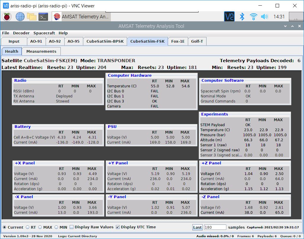
Run FoxTelem in your Ground Station in DUV/FSK mode and you should see the signal. Once payloads are received, look under the CubeSatSim-FSK tab Health tab, Experiment box, you should see STEM Payload OK and numbers for the other fields. In addition, the rotation and acceleration will also be displayed under the +X, +Y, and +Z boxes.
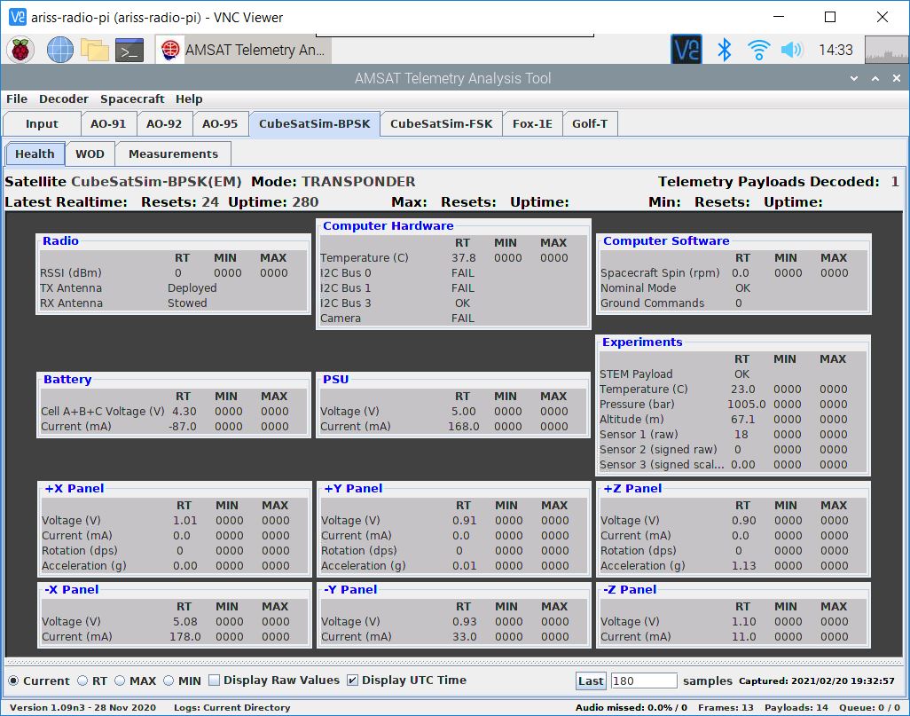
Using the pushbutton, you can switch the CubeSatSim to BPSK mode by pressing and holding the push button until it blinks rapidly three times. Or, you can log into the Pi Zero and enter the command CubeSatSim/config -b then return. The CubeSatSim will reboot and start up in BPSK mode. Then, if you run FoxTelem in BPSK mode, you can look under the CubeSatSim-BPSK tab and see:
On the spinning turntable, you should see 7-10 degrees per second of rotation and the blue LED on the STEM Payload board illuminated. If the CubeSatSim is accelerated greater than 1.2g, the green LED will illuminate on the STEM Payload board.
Camera Testing
Put the CubeSatSim into SSTV mode by pressing and holding the push button until the green power LED blinks four times, then release it. Or, you can log into the Pi Zero and enter the command CubeSatSim/config -s then return. The CubeSatSim will reboot and start up in SSTV mode.
Set your Ground Station to SSTV mode by running either QSSTV on a Raspberry Pi or MMSSTV on Windows. Select the frequency for your CubeSatSim and you should be able to decode the Scottie 2 image.
The first image will be a stored image, but the second and images after that will be Pi Camera photos.
Payload Serial Connection Troubleshooting
If you get the right output in the Serial Monitor in the Arduino IDE, but you don't see the payload data in the APRS packet or FoxTelem says STEM Payload FAIL, here are some things you can check.
Login to your Pi and type these commands:
cd
CubeSatSim/log | grep ayload
The use of ayload instead of payload will give you the log entries for Payload and payload.
You can also send commands over the serial port like you did with the Arduino IDE using these commands:
sudo apt-get install -y minicom
sudo systemctl stop cubesatsim
minicom -b 115200 -o -D /dev/serial0
Now you should see the same output you saw in the Arduino Serial Monitor.
To exit, you have to type Control-A then z then x then hit Return.
Adding Additional Sensors
Here's how to add more sensors to your STEM Payload board.
Additional Sensor Info
The BME-280 Temperature Humidity Barometric Pressure Sensor (small purple board):
https://lastminuteengineers.com/bme280-arduino-tutorial/
Here is some code that displays all the values:
https://github.com/alanbjohnston/CubeSatSim/tree/master/stempayload/bme280test
The MPU-6050 (GY-521) 3-Axis Accelerometer and Gyro (larger blue board with green LED):
Here is some code that displays all the values:
https://github.com/alanbjohnston/CubeSatSim/tree/master/stempayload/GetAllData