5. Battery Board - alanbjohnston/CubeSatSim GitHub Wiki
If the images fail to load, you can download a PDF of the page.
5. Battery Board
These instructions are to build and test the Battery board version v2.1.

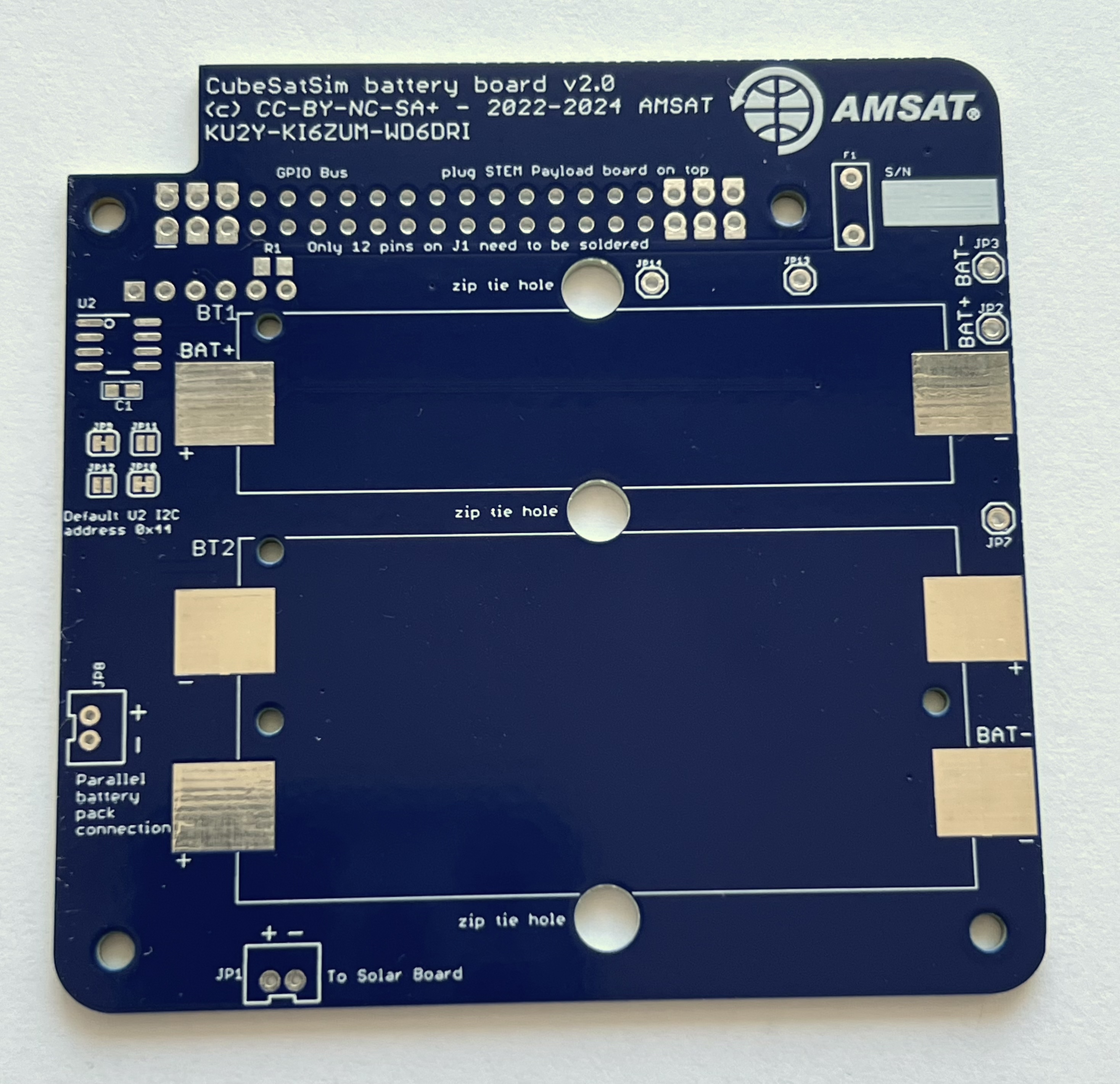
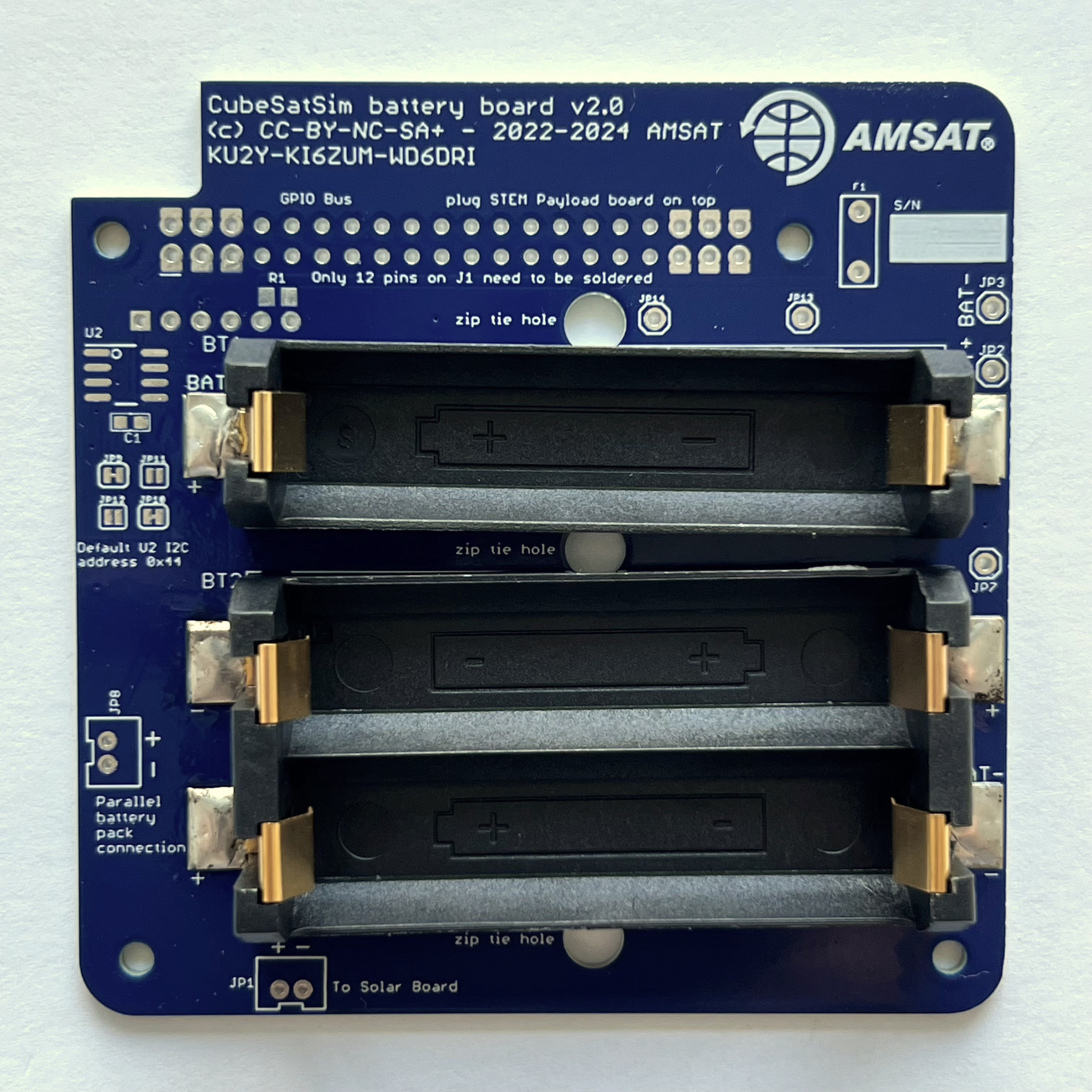
Here is the v2.1 PCB top and bottom:
Here is the schematic:
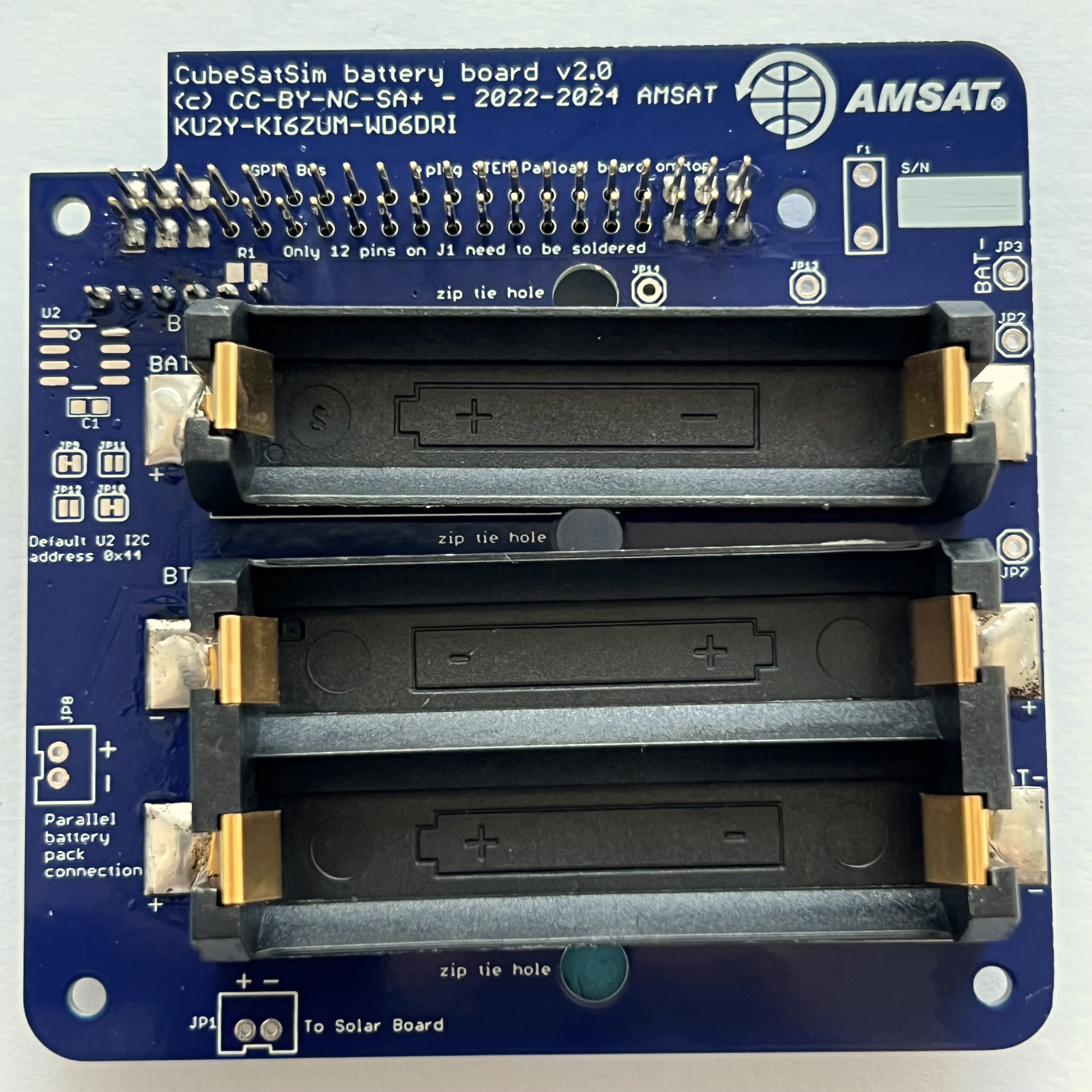
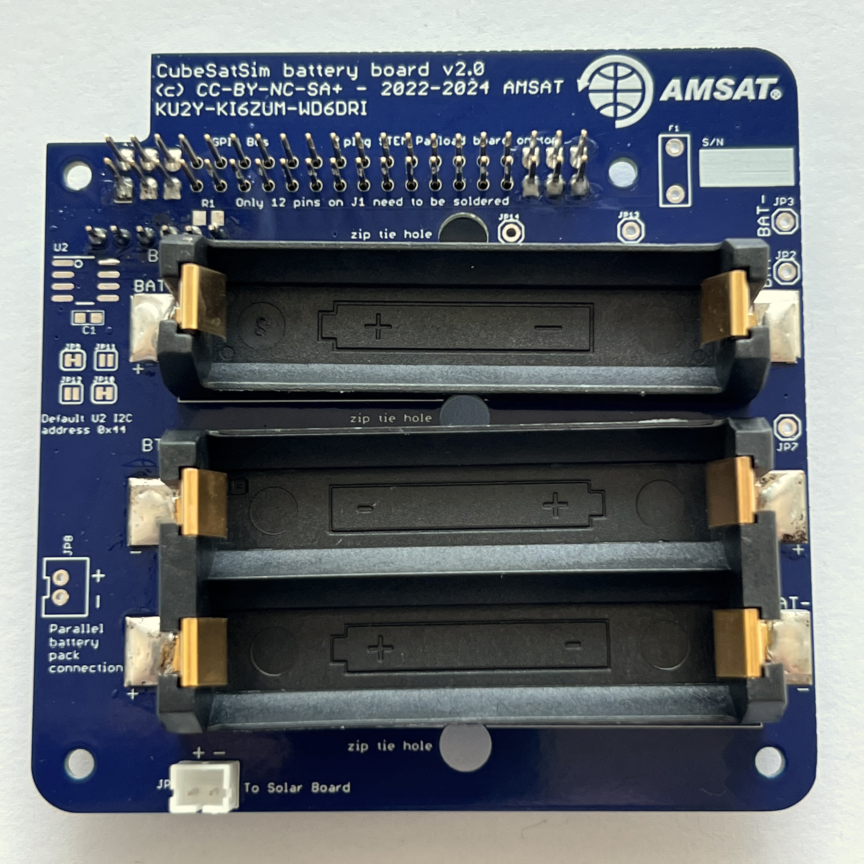
Here is the board with the top on the left with the AMSAT logo and the bottom on the right:
You will need these tools:
- Safety glasses (to protect eyes while soldering or trimming leads)
- Soldering iron and solder (I use lead-free solder, but leaded solder is easier to work with)
- Liquid flux, either in a bottle or pen
Other tools that are helpful:
- Multimeter (to read battery voltage)
- Blue mounting putty(to hold components in place while soldering)
Checklist
The BOM has a sheet "By Steps" which lists the parts needed for each step in order. https://cubesatsim/bom If you have a Google account, you can make a copy of this spreadsheet ("File" then "Make a Copy") and check off each part as you install it.
For example, here is the checklist for this step:
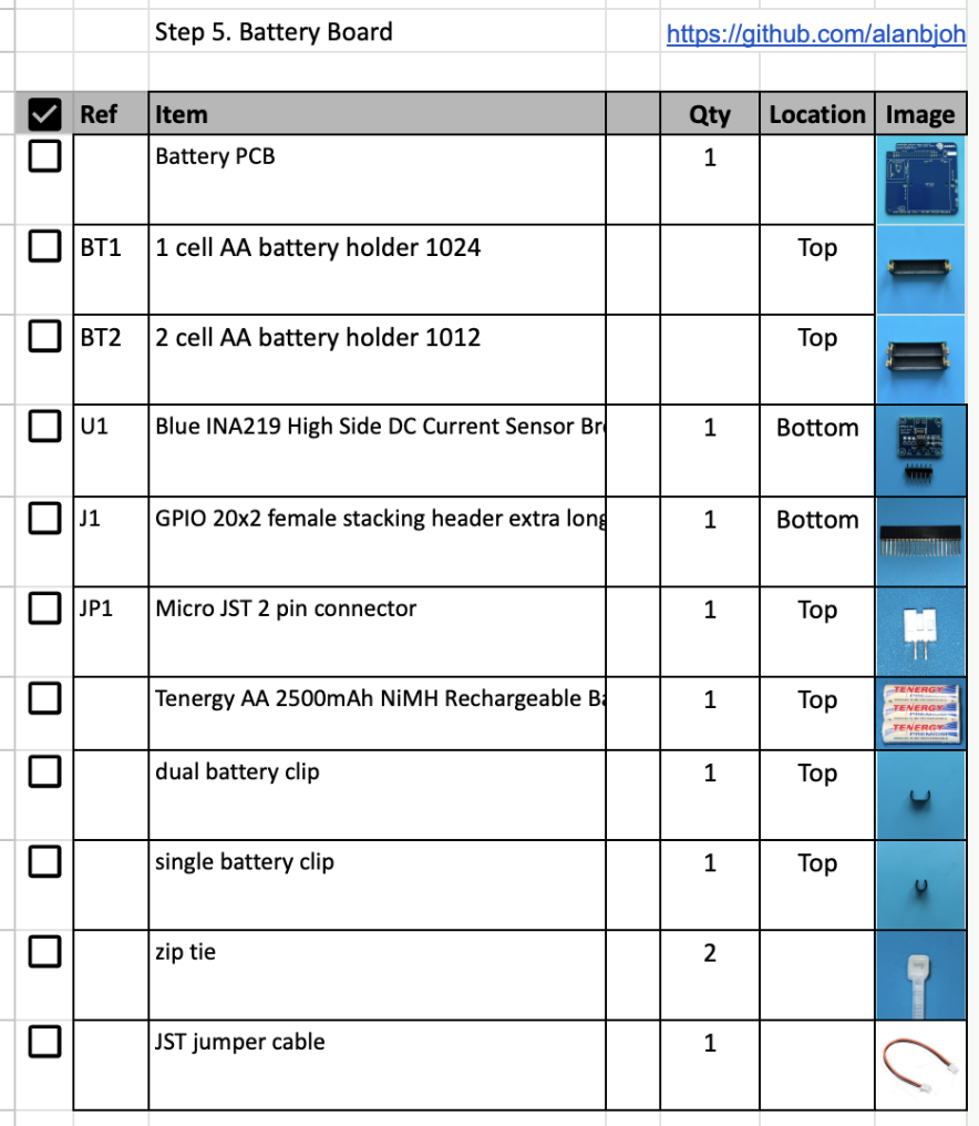
Note: you can use either the black 2800 mAh batteries or the white 2500 mAh batteries. Both will work, but the black batteries will last a little longer.
Battery Board Instructions
Video
Here is a video of this step.
Assembly
Note that the photos show the v2.0 Battery board, but the assembly is identical.
The Battery Board stacks on top of the Pi Zero and under the Main Board.
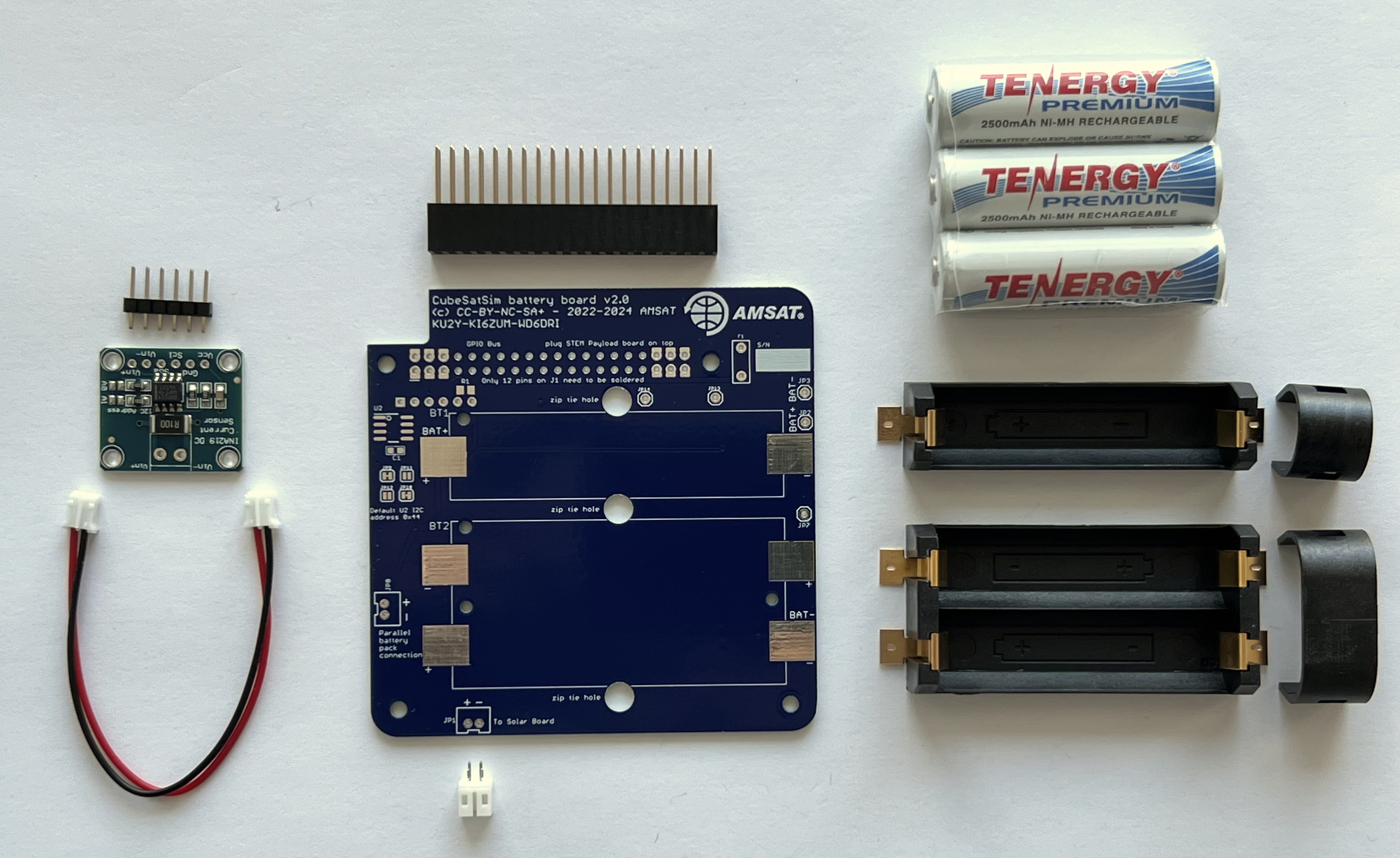
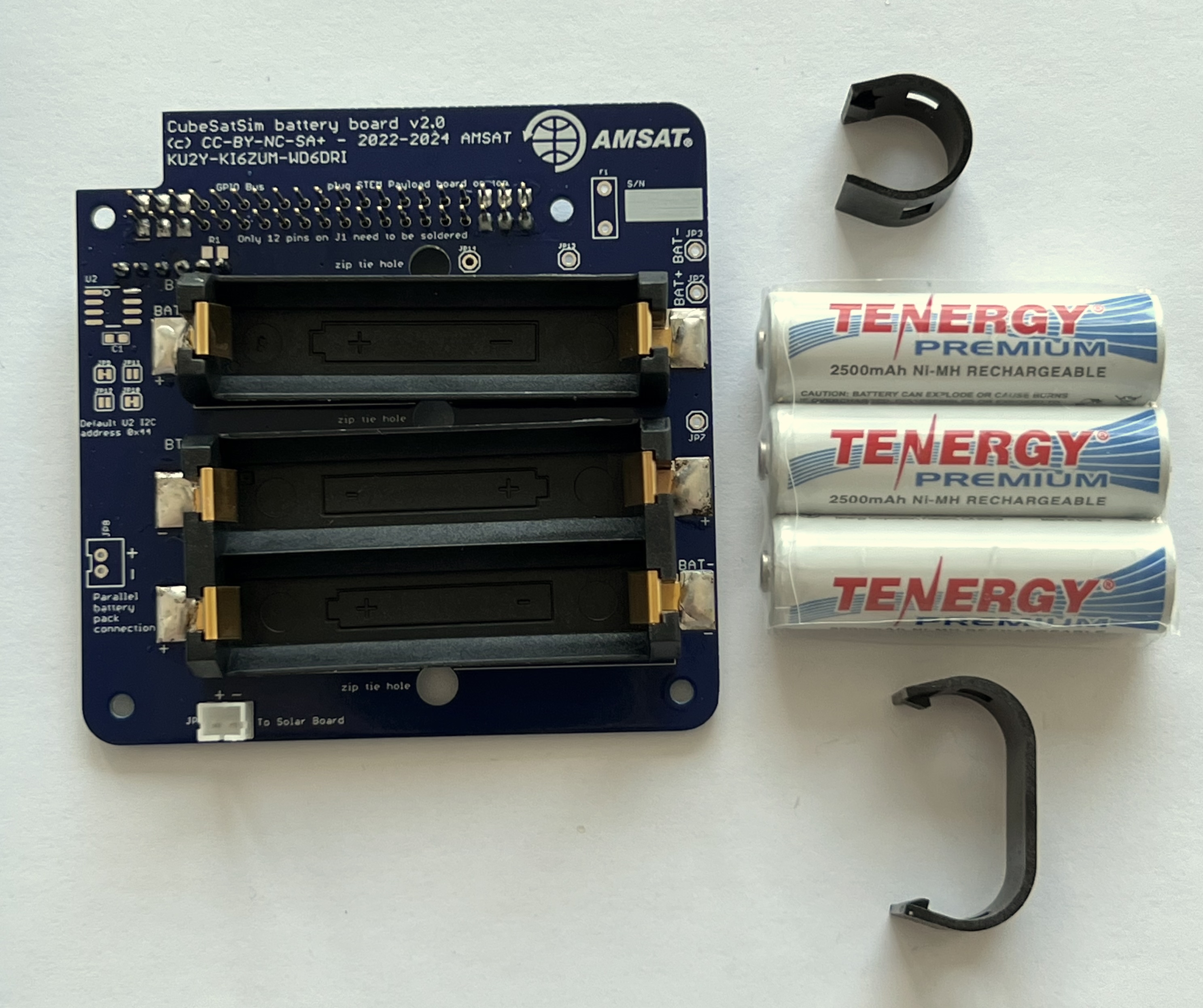
You will need the following parts to make the Battery board as described in the BOM https://cubesatsim.org/bom:
- Battery PCB
- Stacking GPIO header J1
- Three Nickel Metal Hydride (NiMH) cells (AA size)
- Battery holders (AA size) BT1 and BT2 (Note: if the double holder is out of stock, you can use three single holders).
- INA219 blue voltage and current sensor board CJMCU-219 U1
- JST 2.0 jumper cable
- JST 2.0 connector JP1
- Two small zip ties
The parts are shown here:
If you are using three single battery holders, here's how it looks:

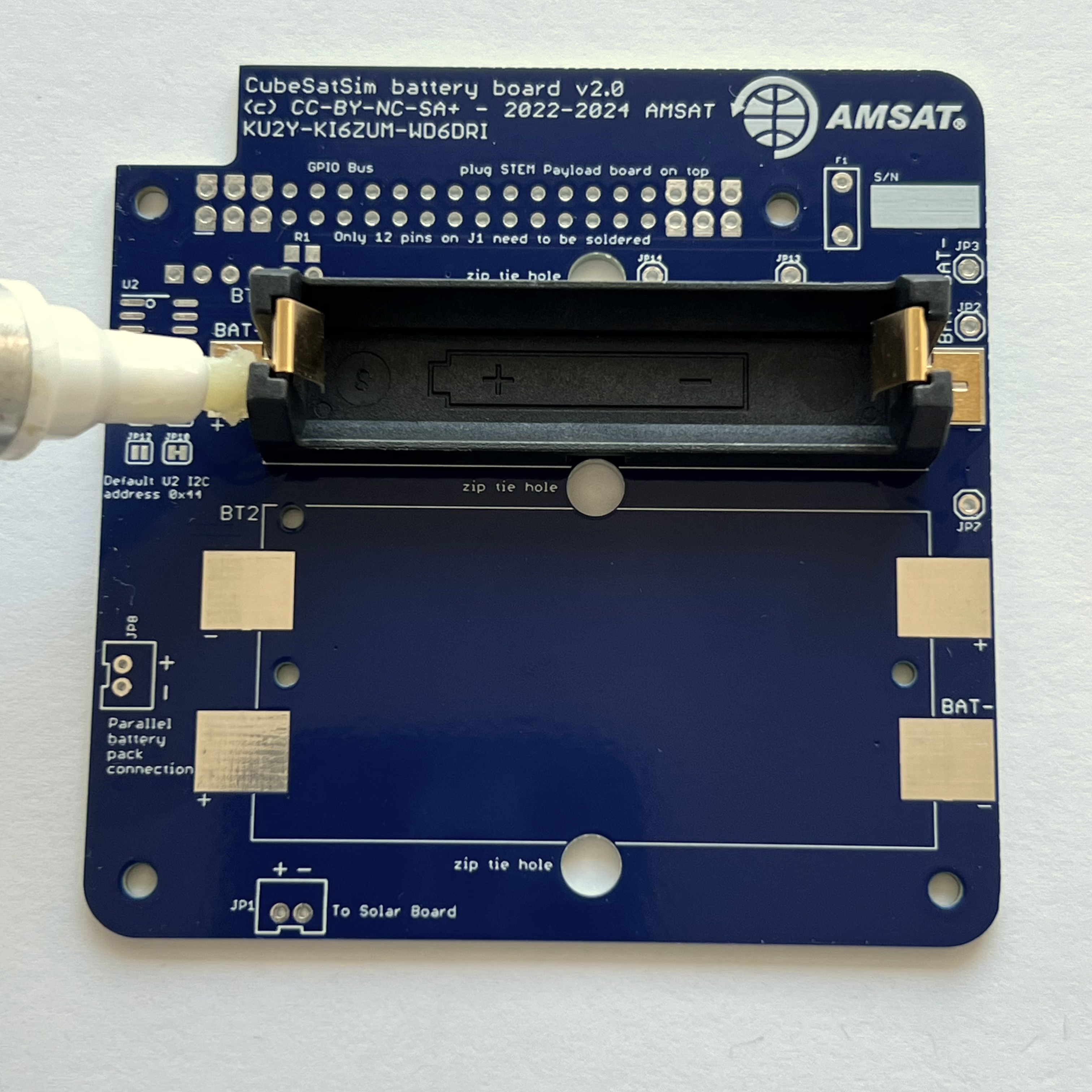
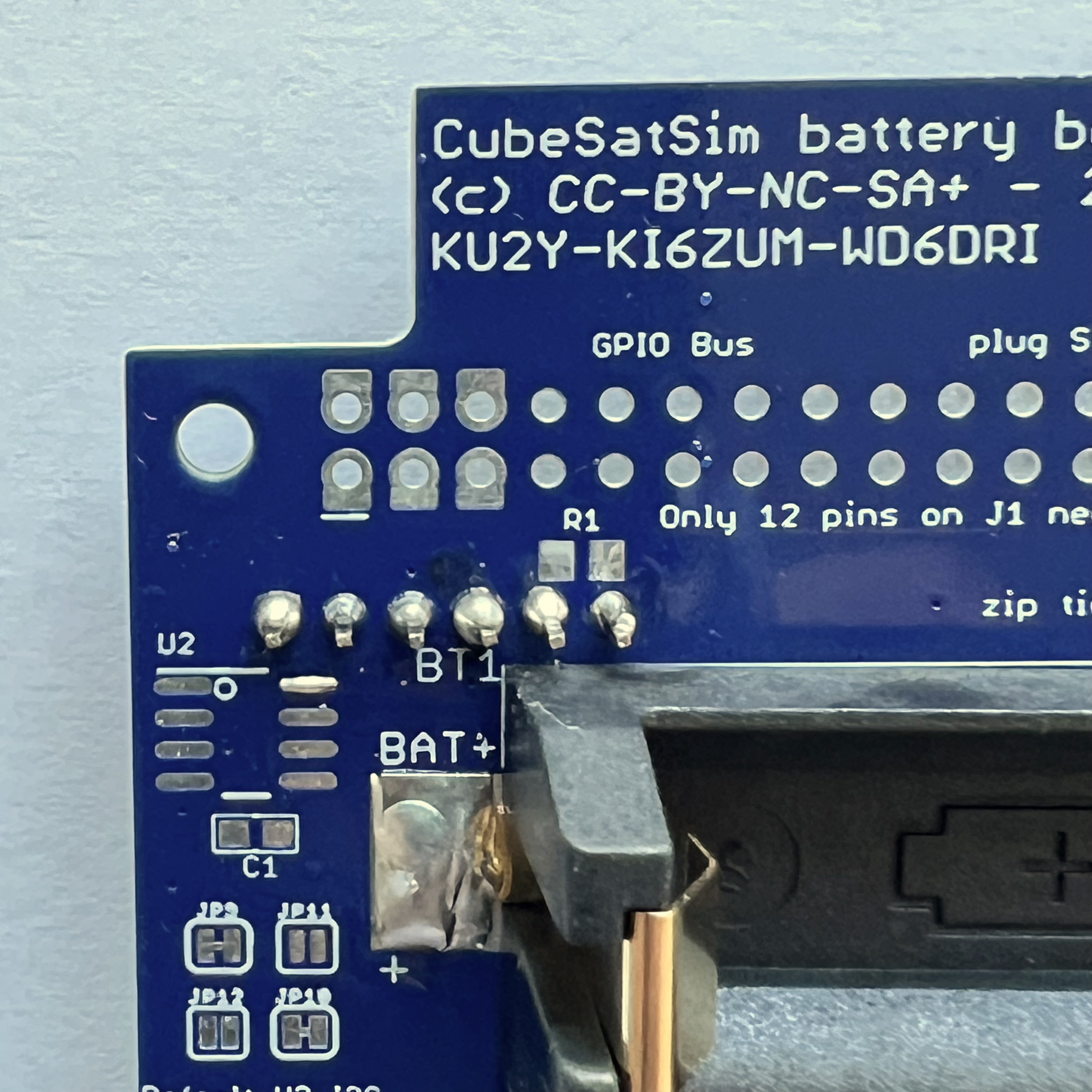
On the top of the PCB, apply liquid flux to the six pads for the battery holders:
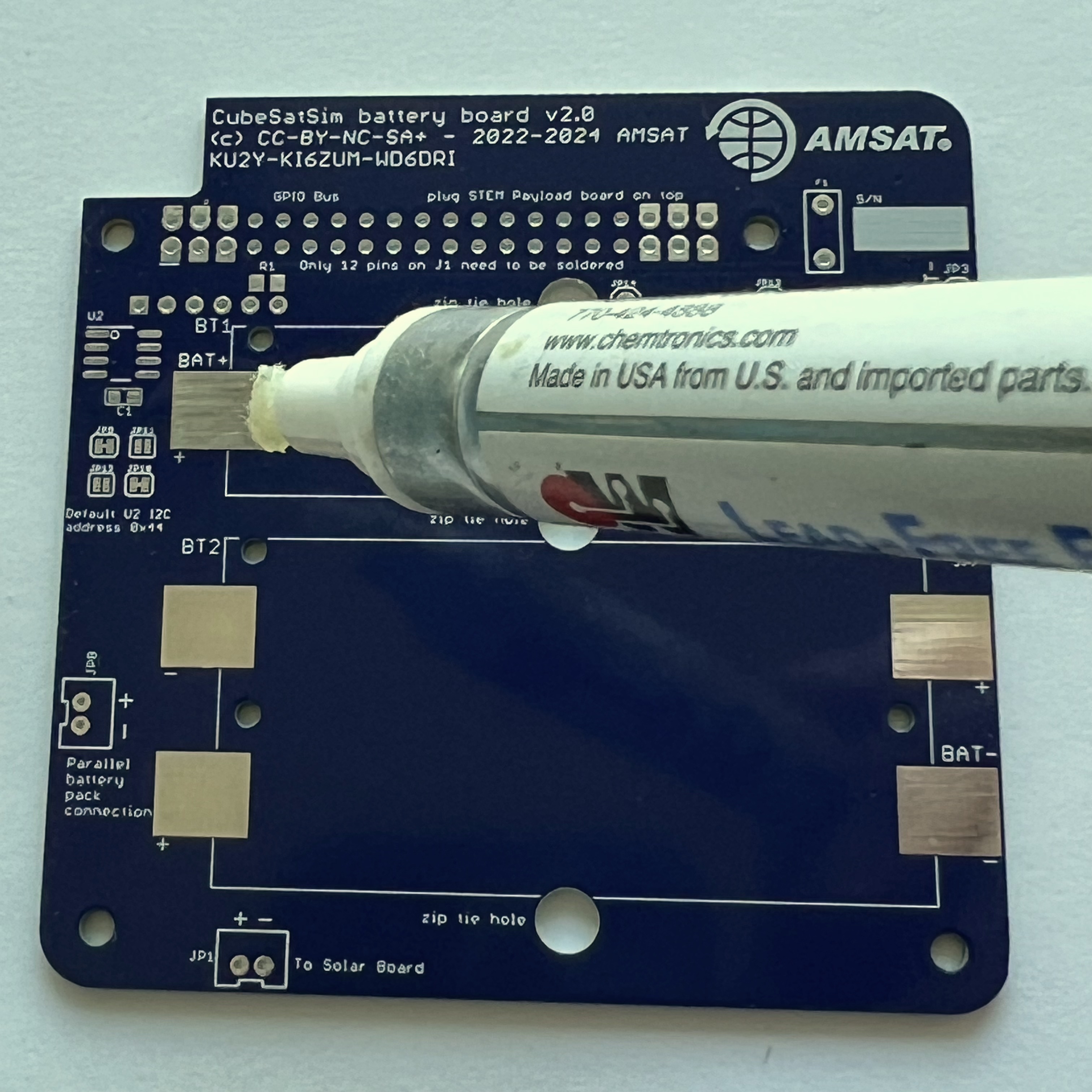
Then mount the battery holder BT1. There is a small tab on the bottom of the battery holders that fits in a hole in the PCB - make sure it is inserted so the battery polarity is correct and the holder is flat against the PCB. Apply more liquid flux on part:
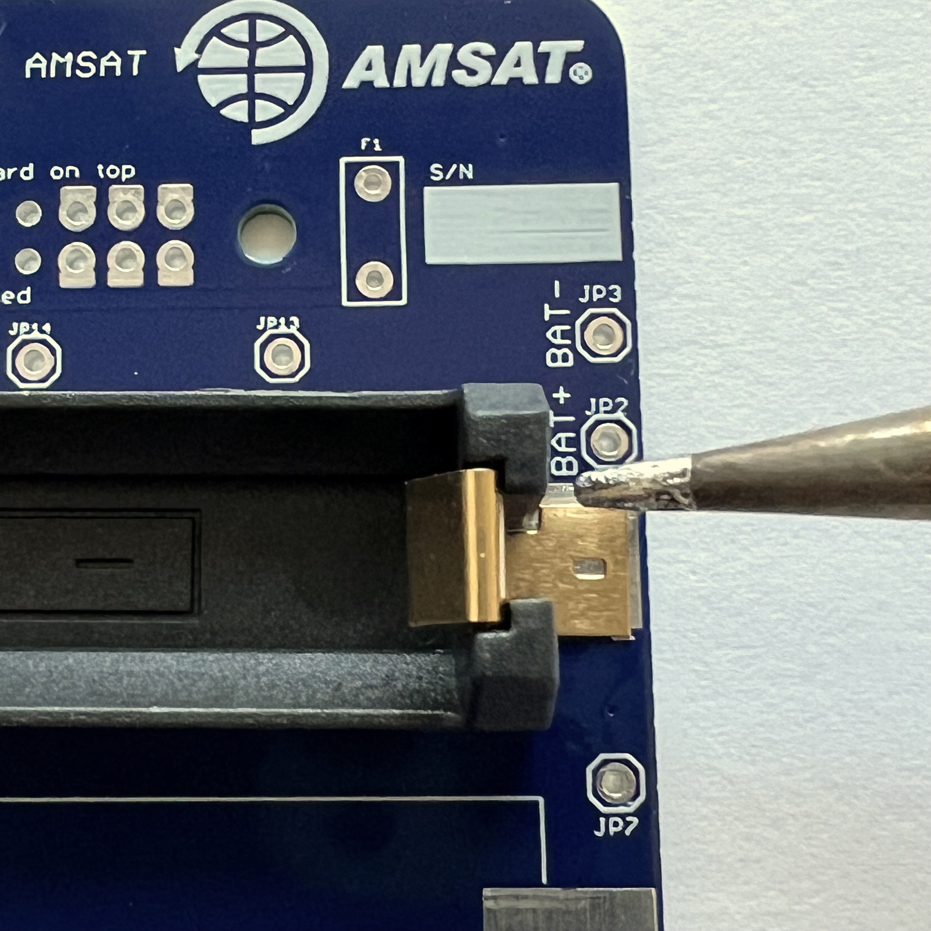
When soldering, make sure you apply some heat to the PCB, not just the part. This will ensure that the solder flows around and under the part
Here's how it looks when the pad is soldered:
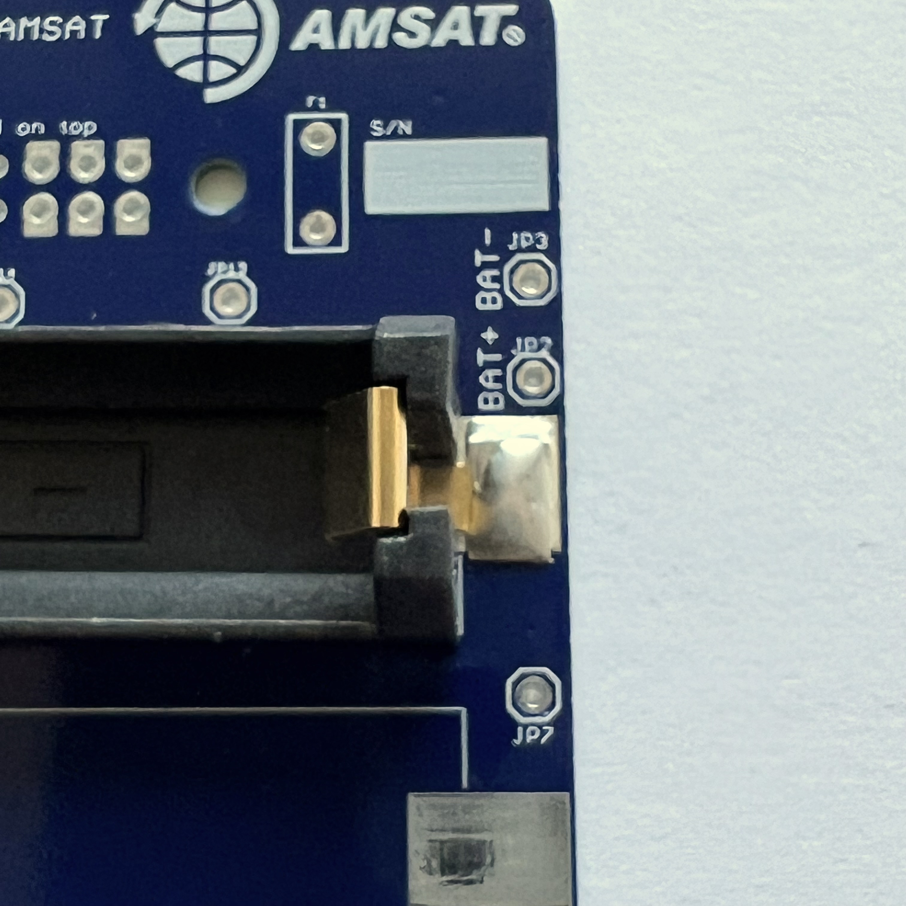
Solder the other pad (note this part is a little crooked):
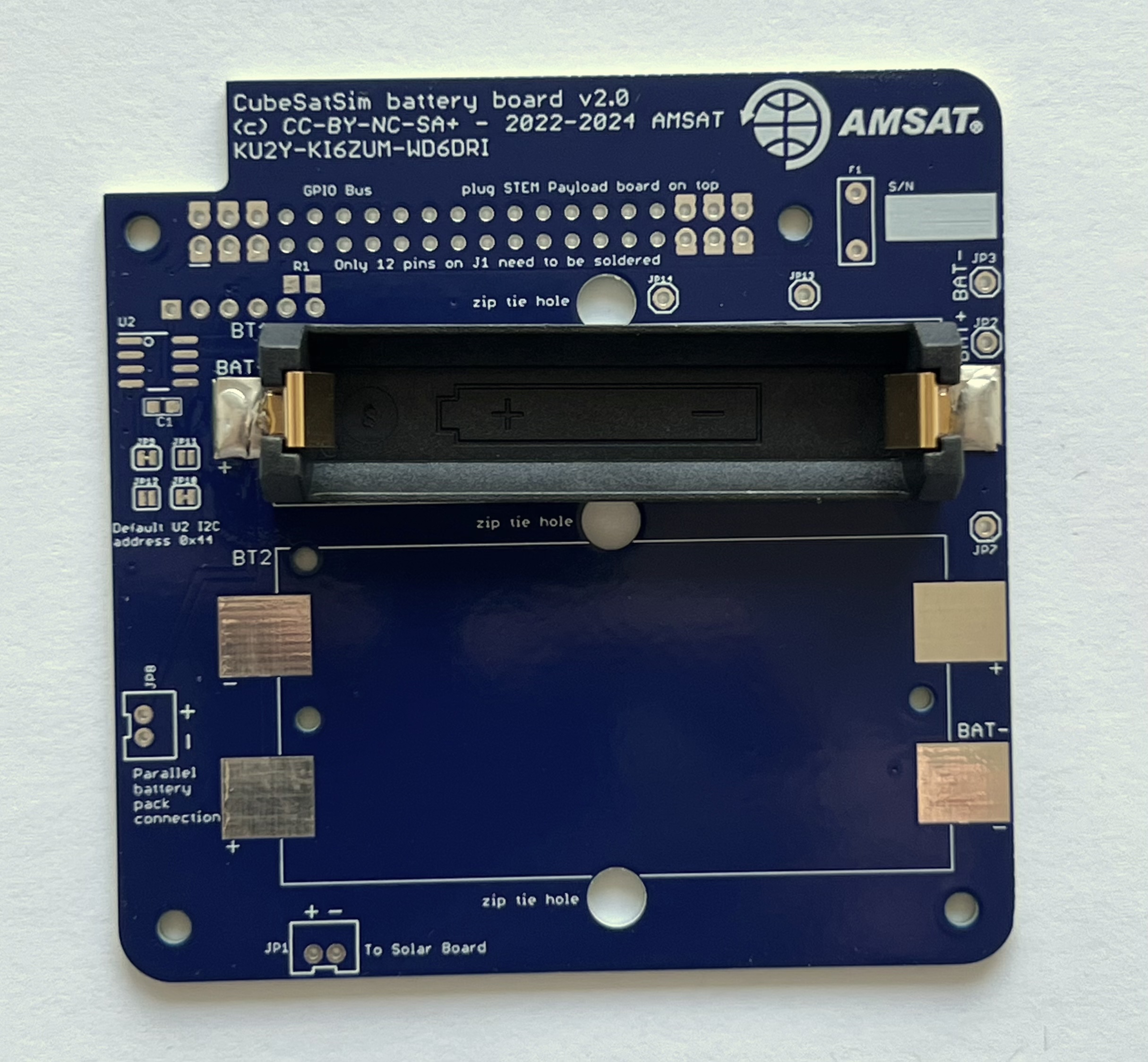
Then mount battery holder BT2:
Again, there is a small tab on the bottom of the battery holders that fits in a hole in the PCB - make sure it is inserted so the battery polarity is correct and the holder is flat against the PCB.
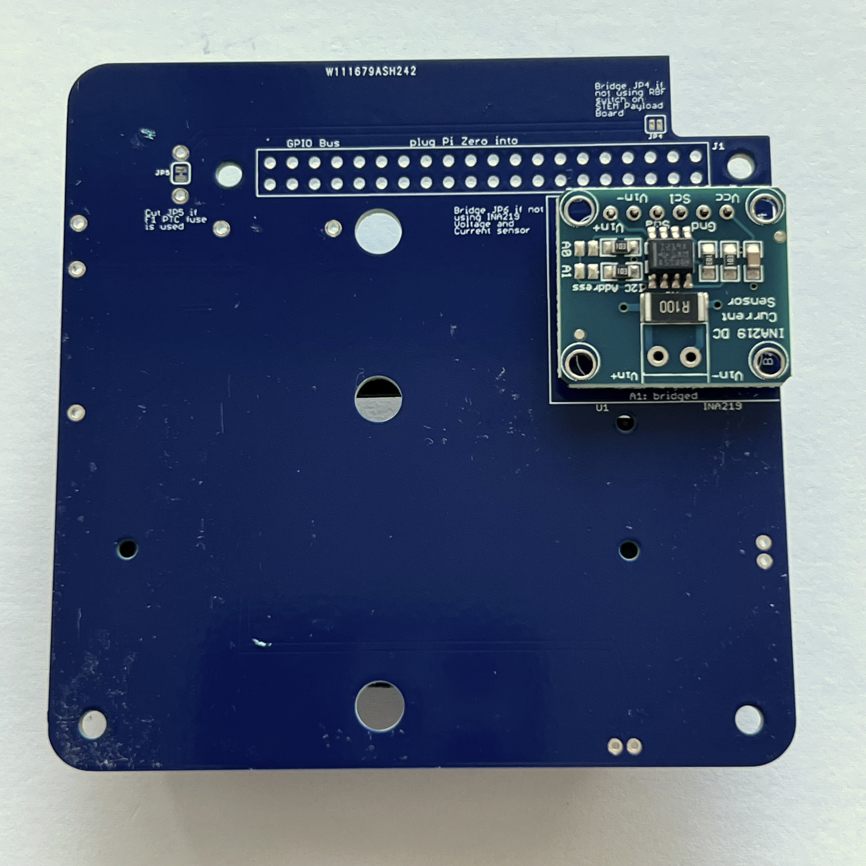
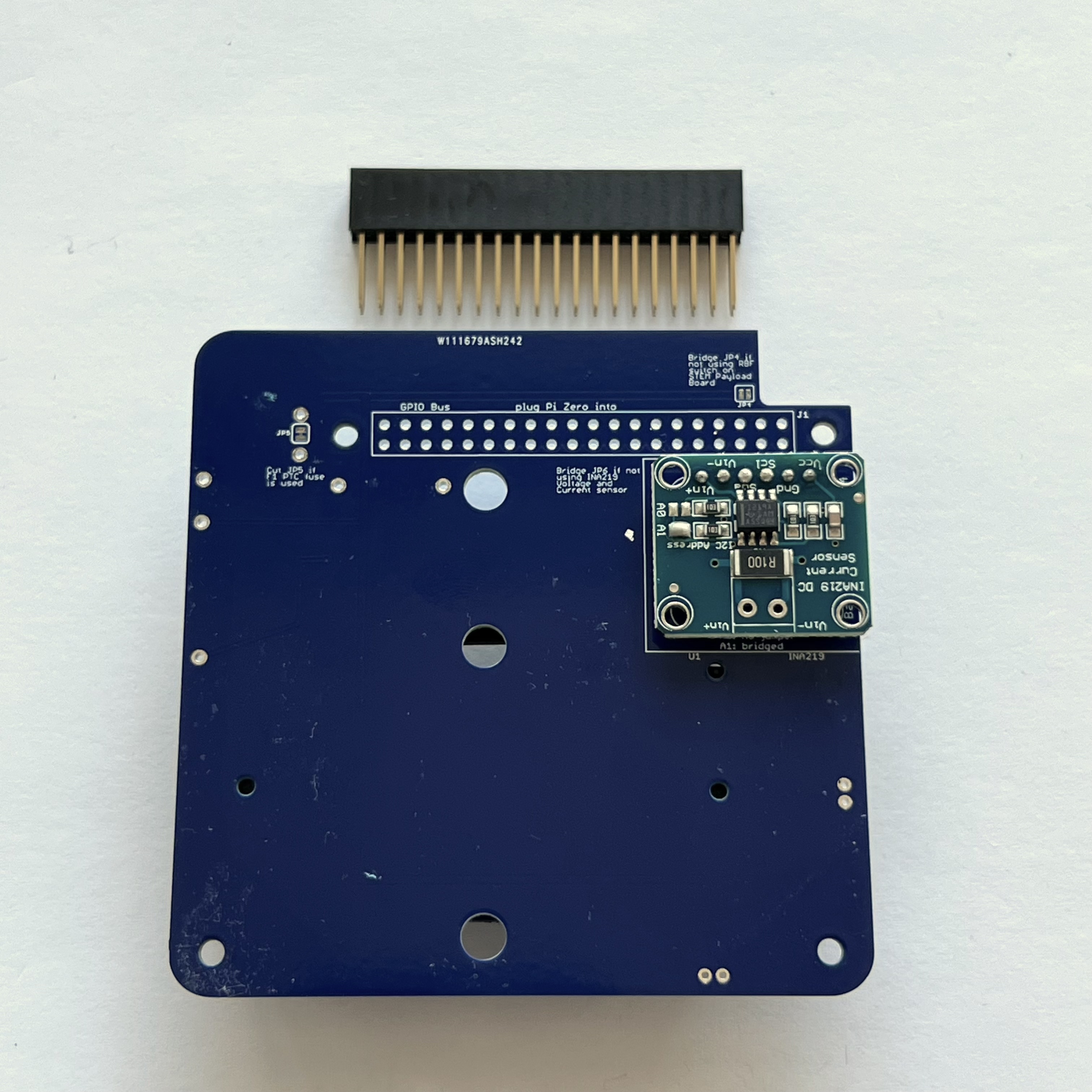
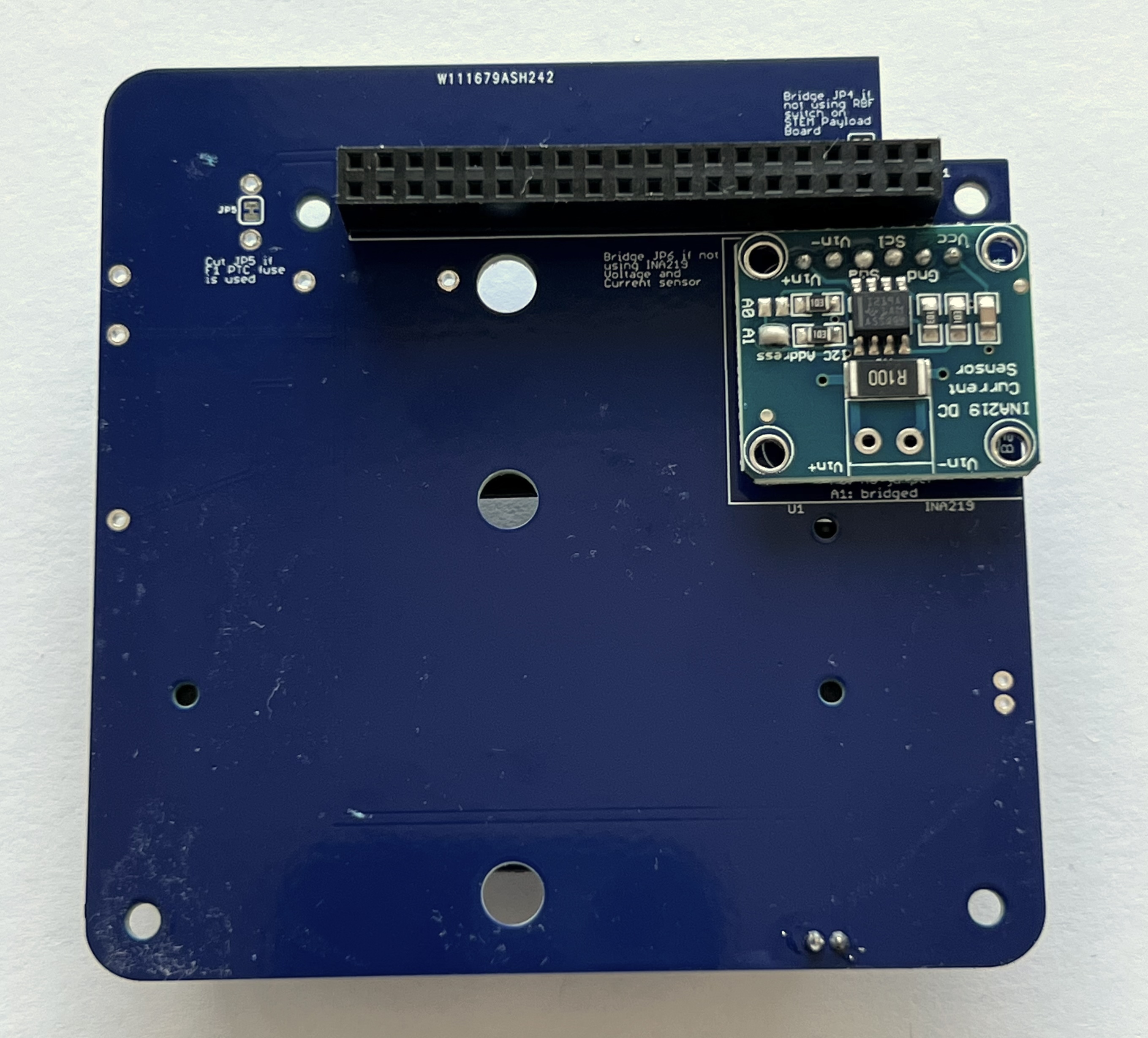
Next, turn the PCB upside down, as the blue INA219 board CJMCU-219 is mounted on the bottom of the PCB:
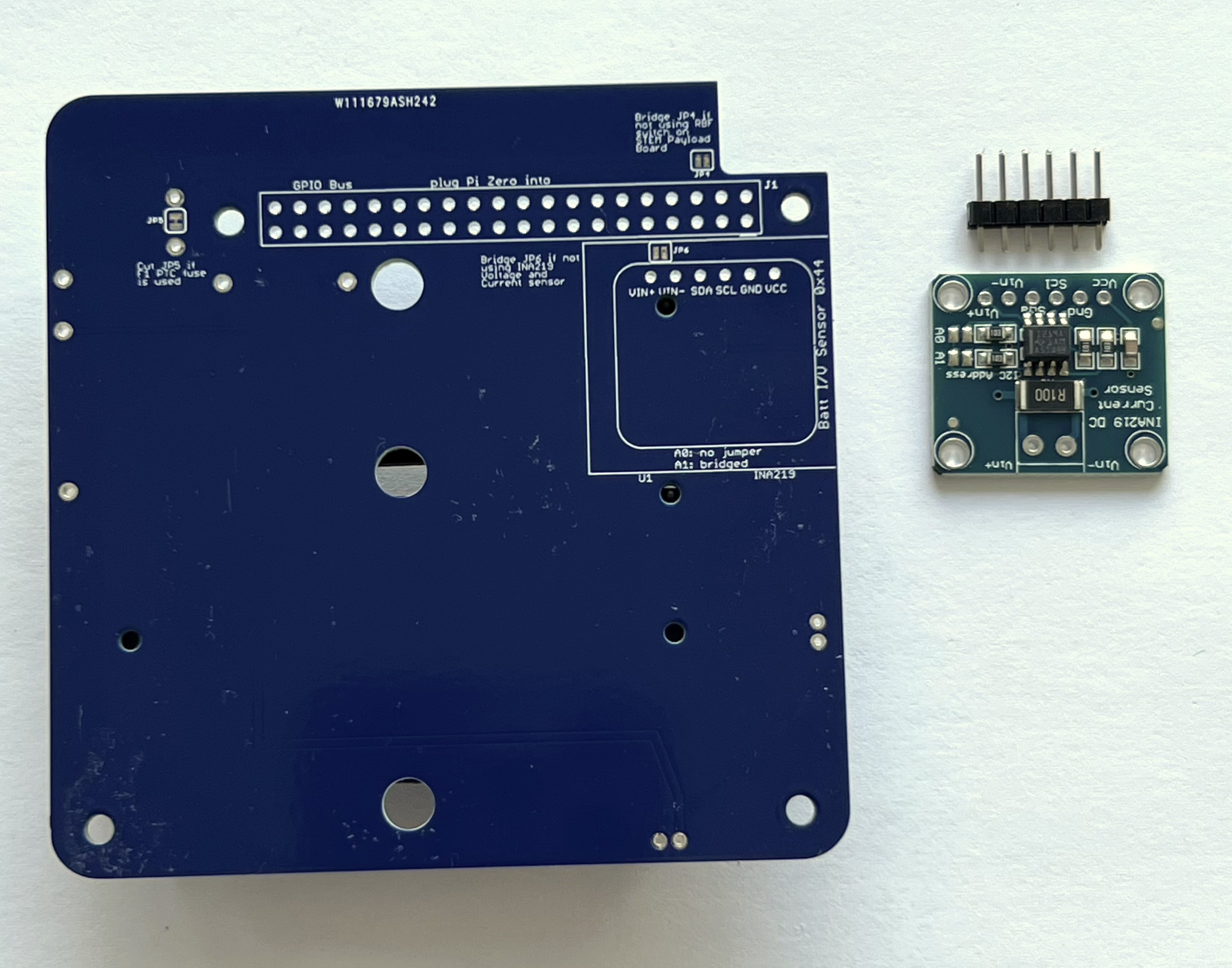
Insert the 1x6 male pin header into the PCB and hold in place with blue putty:
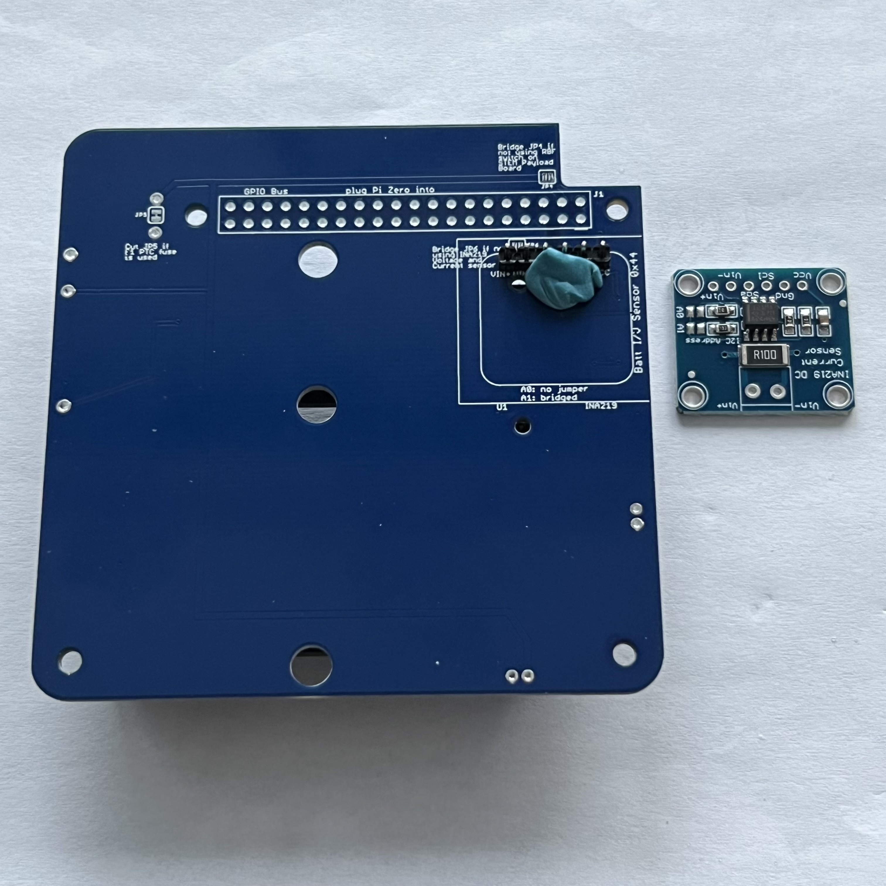
Solder the six pins on the other side.
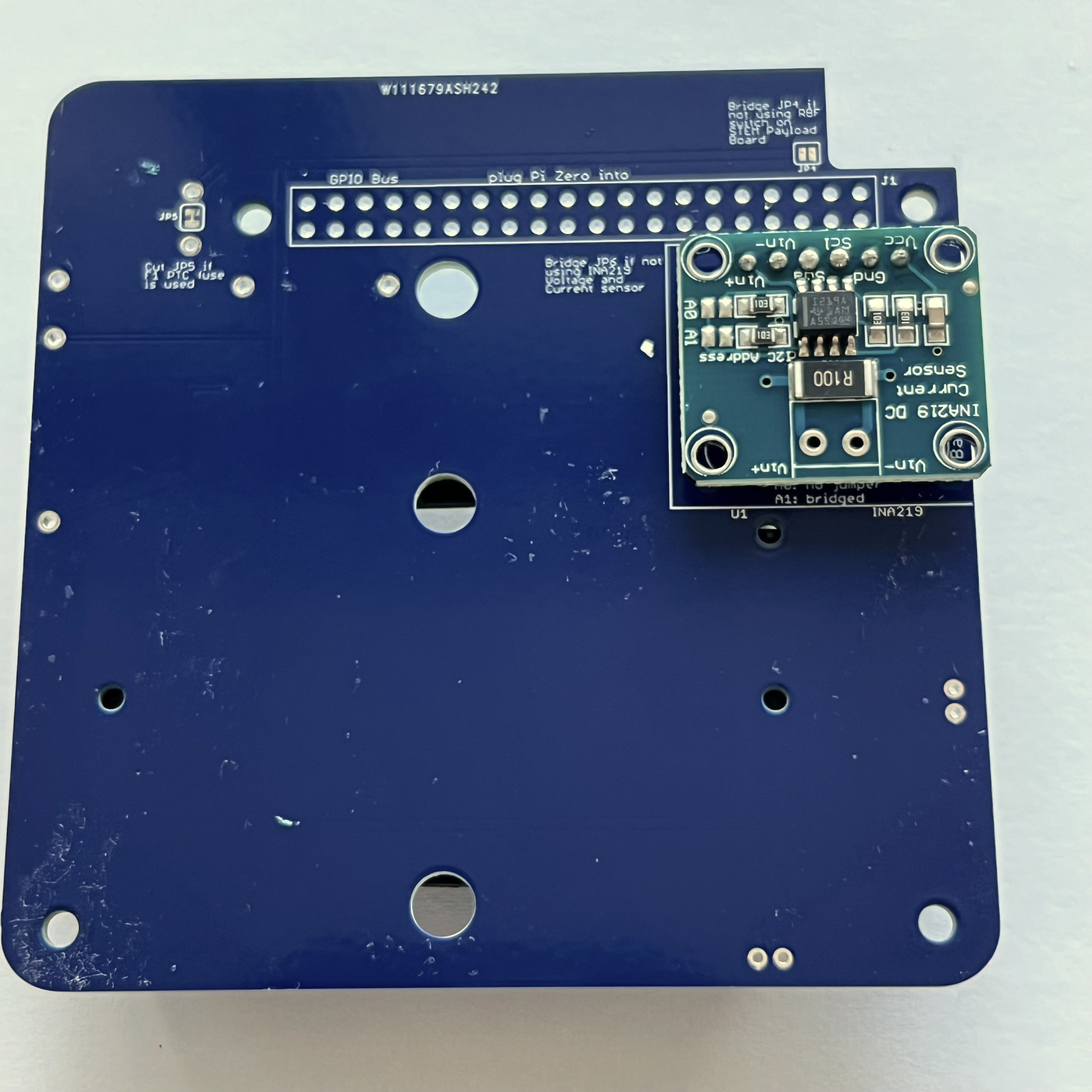
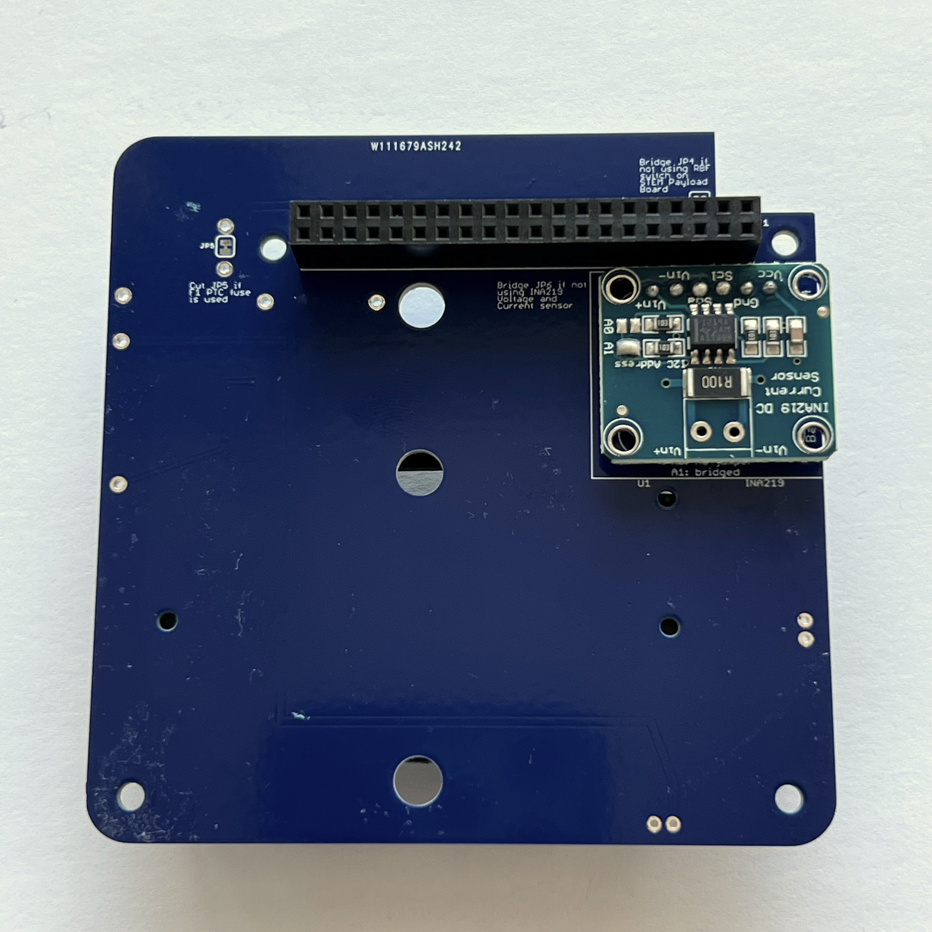
Then place the INA219 board on the pin header. Use the blue putty so it sits horizontally:
Solder the six pins on top of the INA219 board:
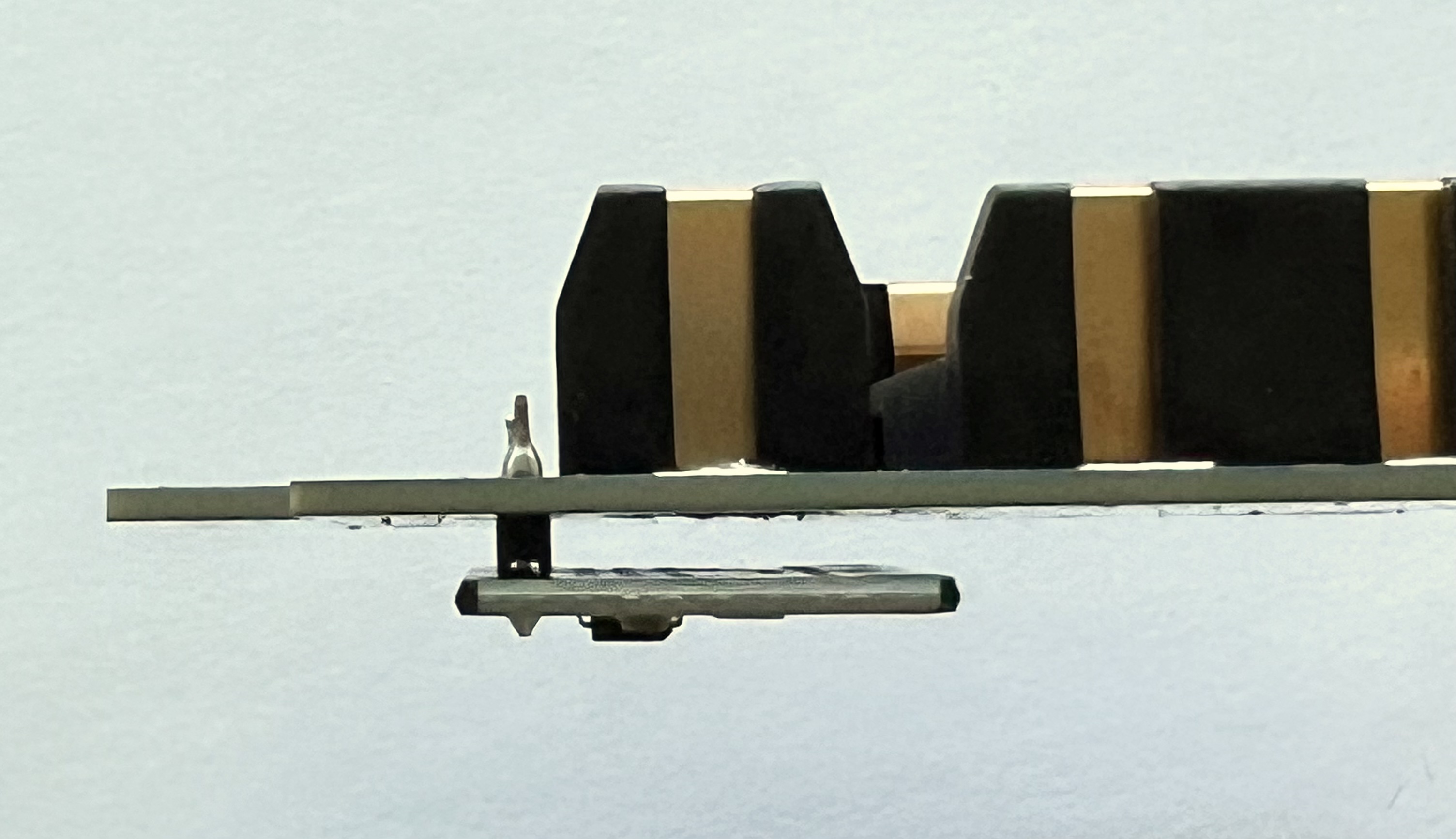
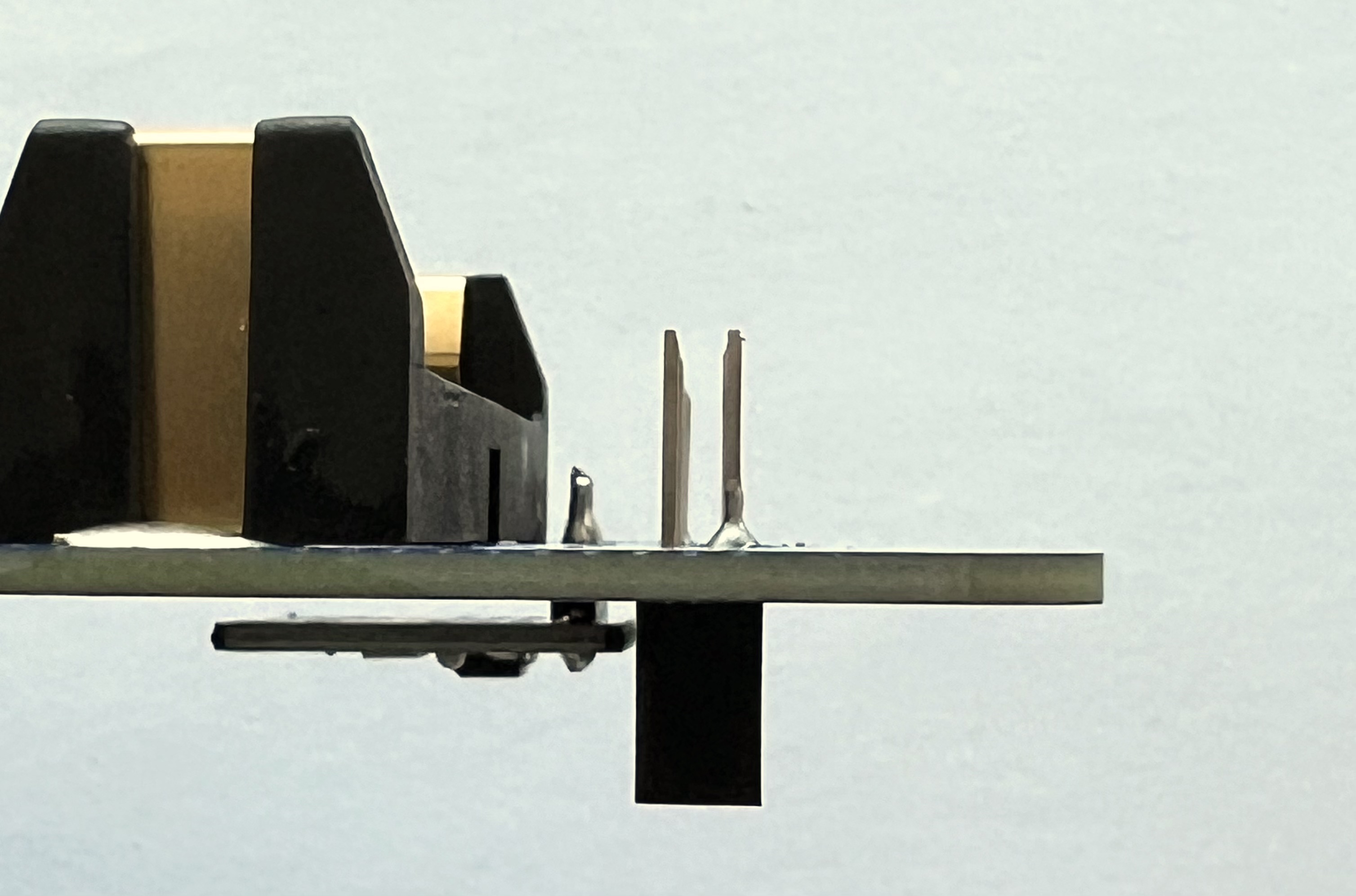
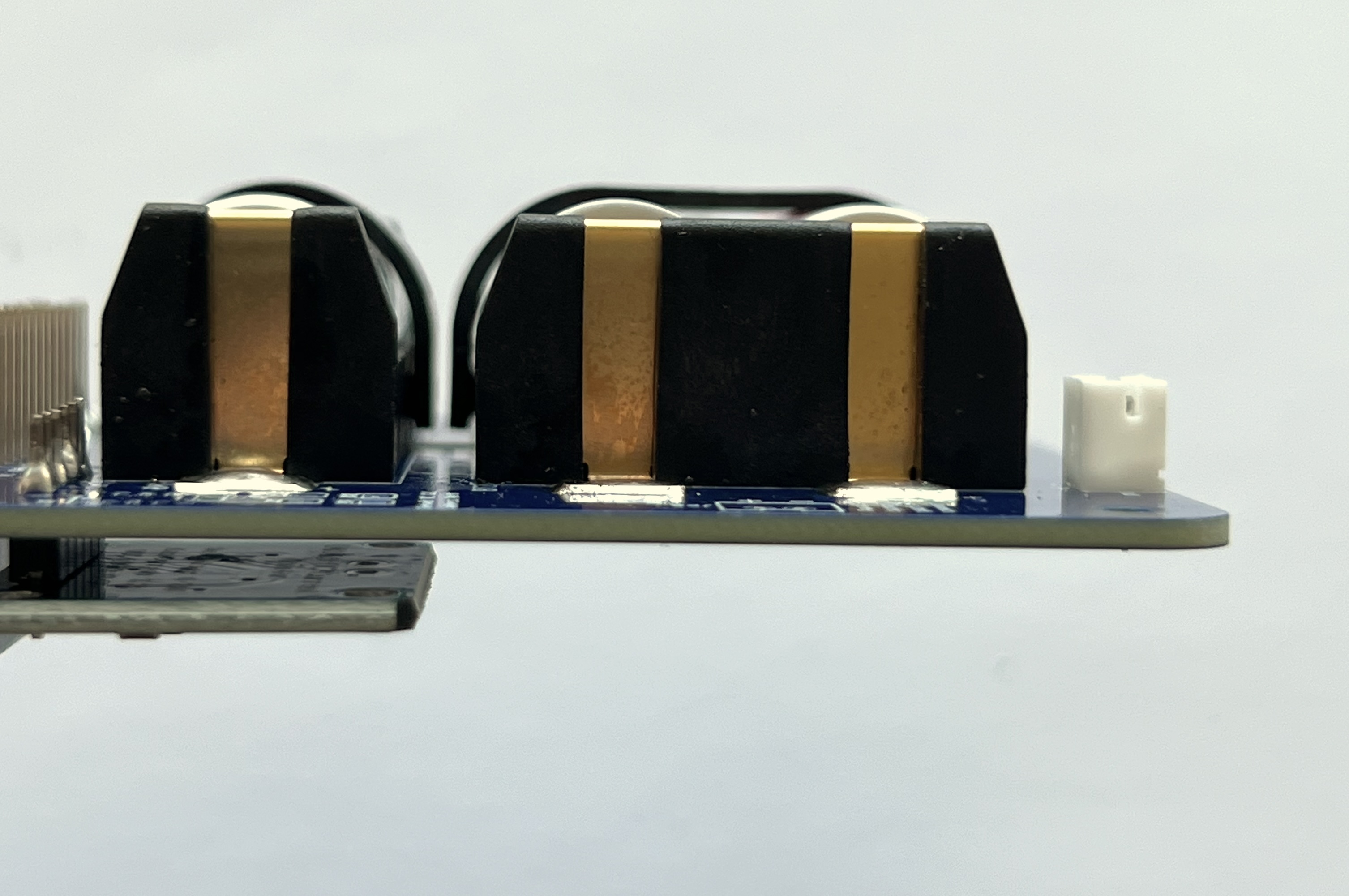
Here's how it looks from the side:
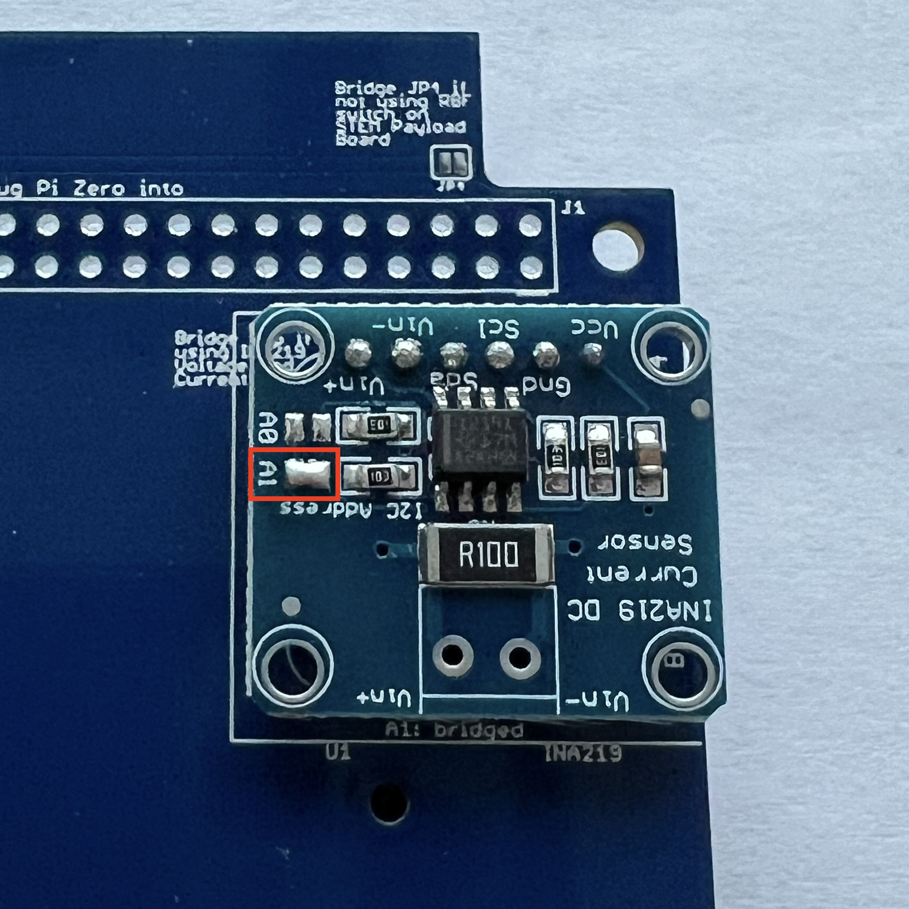
The jumper A1 needs to be bridged with a blob of solder to set the I2C address for the board:
Next, also on the bottom of the PCB, mount the stacking GPIO header J1:
Insert it on the bottom as shown:
Flip the PCB to the top. Solder one pin on either side, using the pad next to each pin to heat both the pin and the pad:
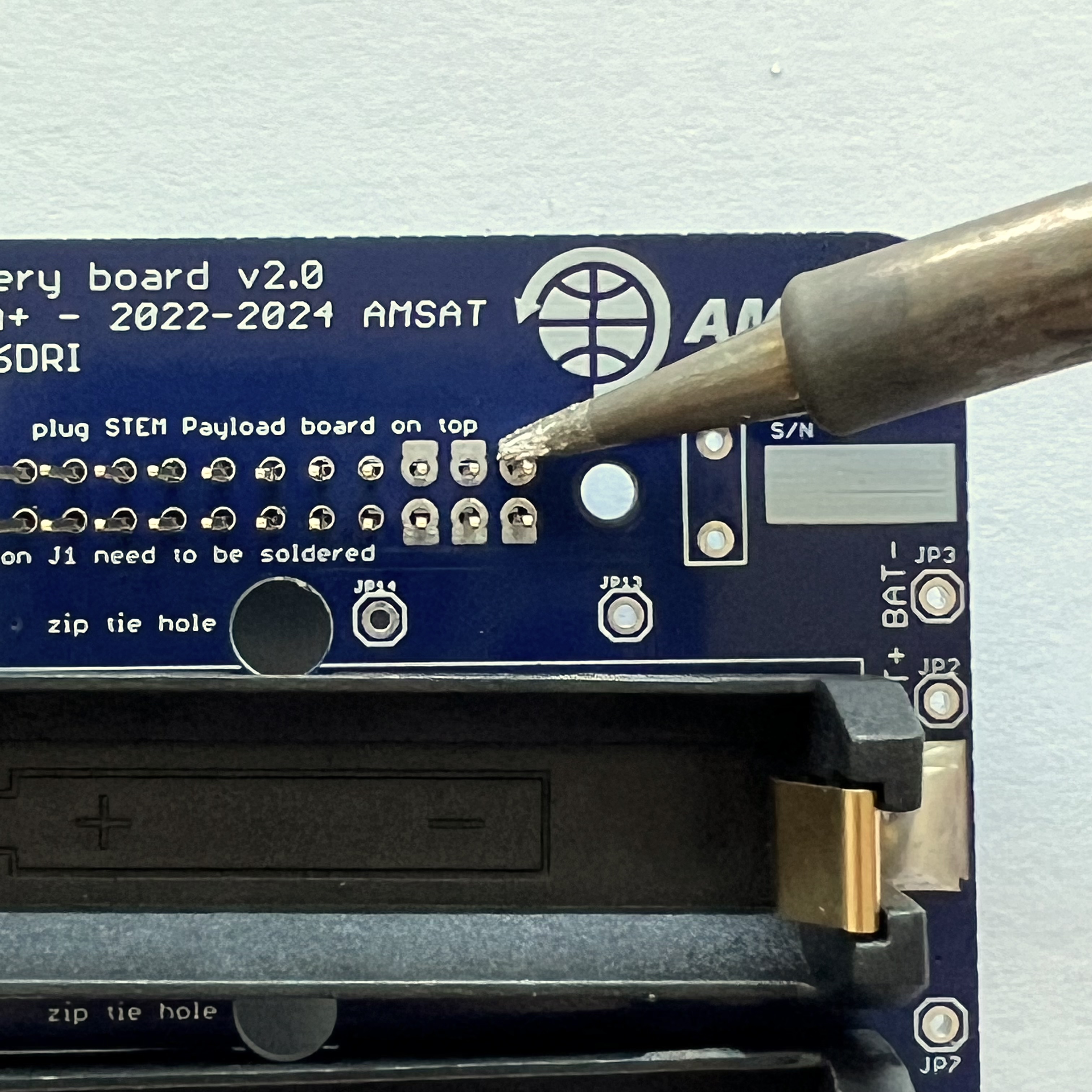
Make sure you don't get solder on the upper part of the pin or it won't insert into the other board:
Make sure the GPIO header is fully inserted and straight and on the correct side:
Only solder six pins on either side, as shown in the next photo:
Next, on the top of the PCB, insert the JST connector JP1.
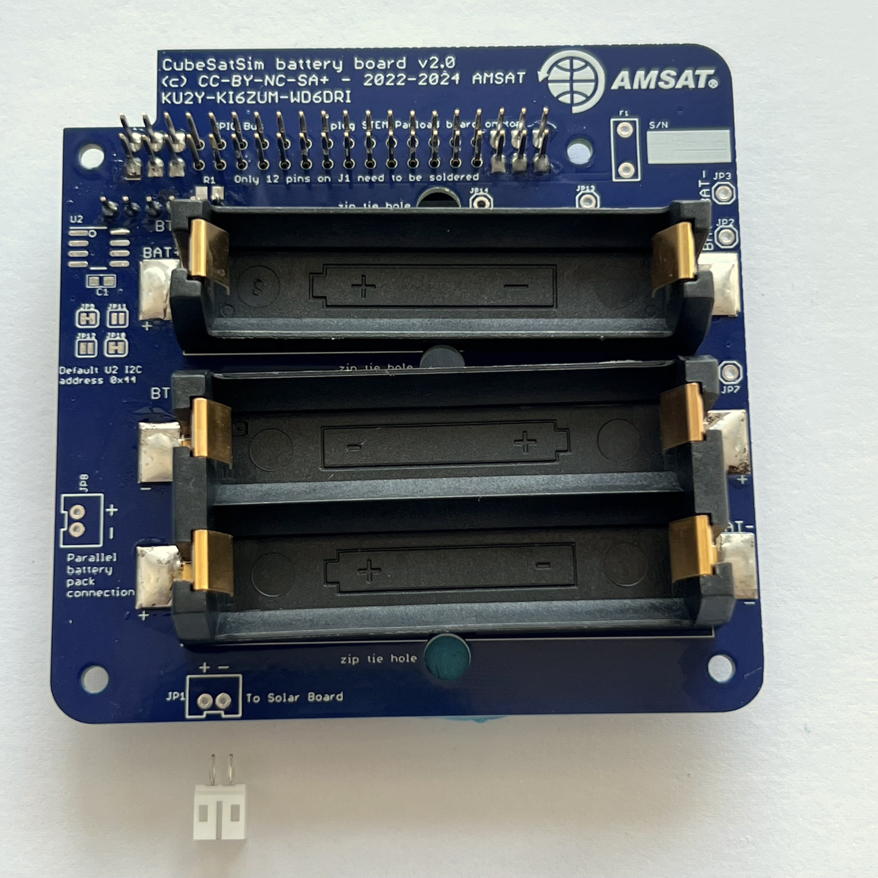
Make sure the slot is facing the edge of the PCB and hold in place with blue putty:
Solder the pins on the other side:
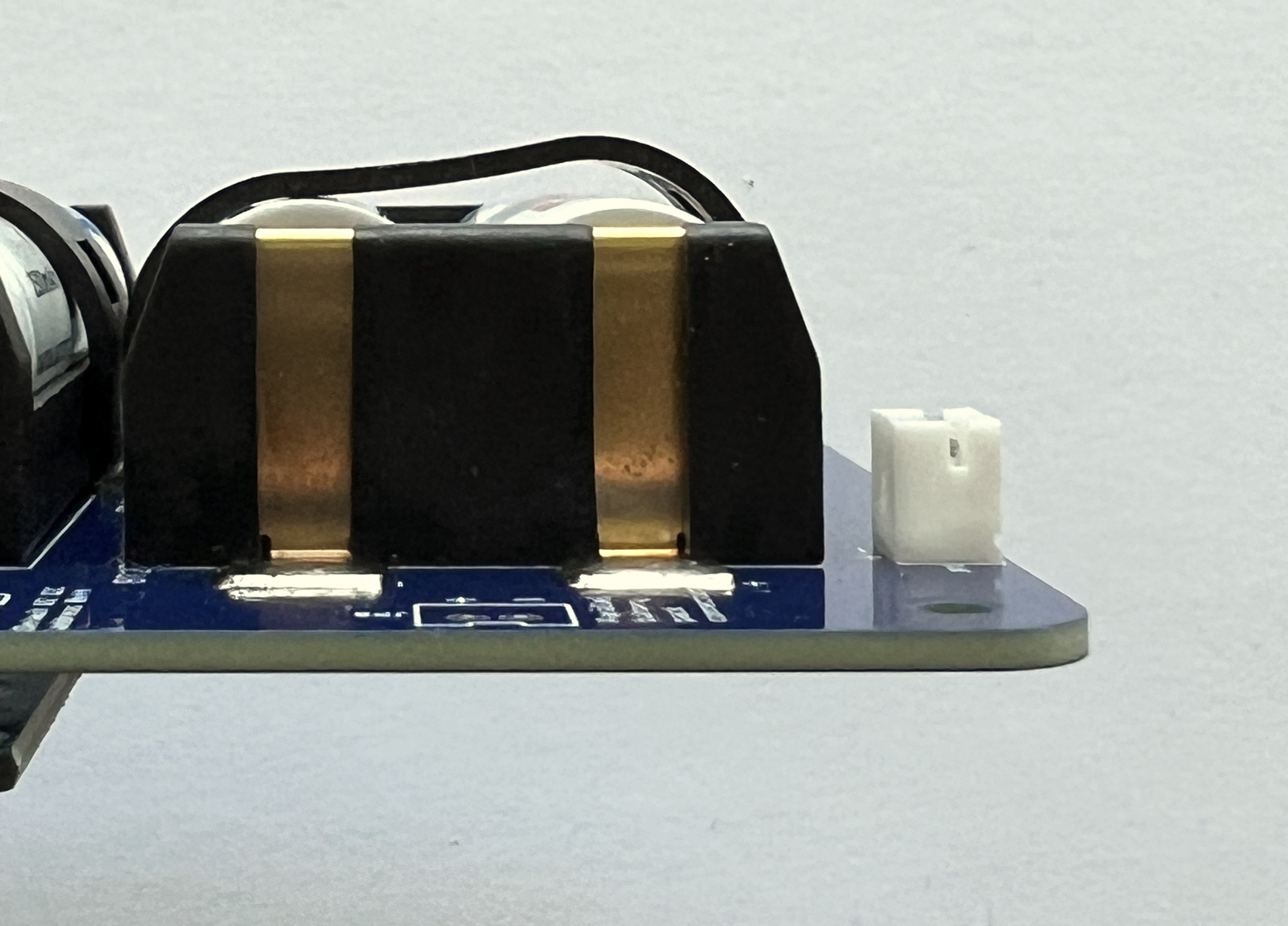
Here's how it looks from the side:
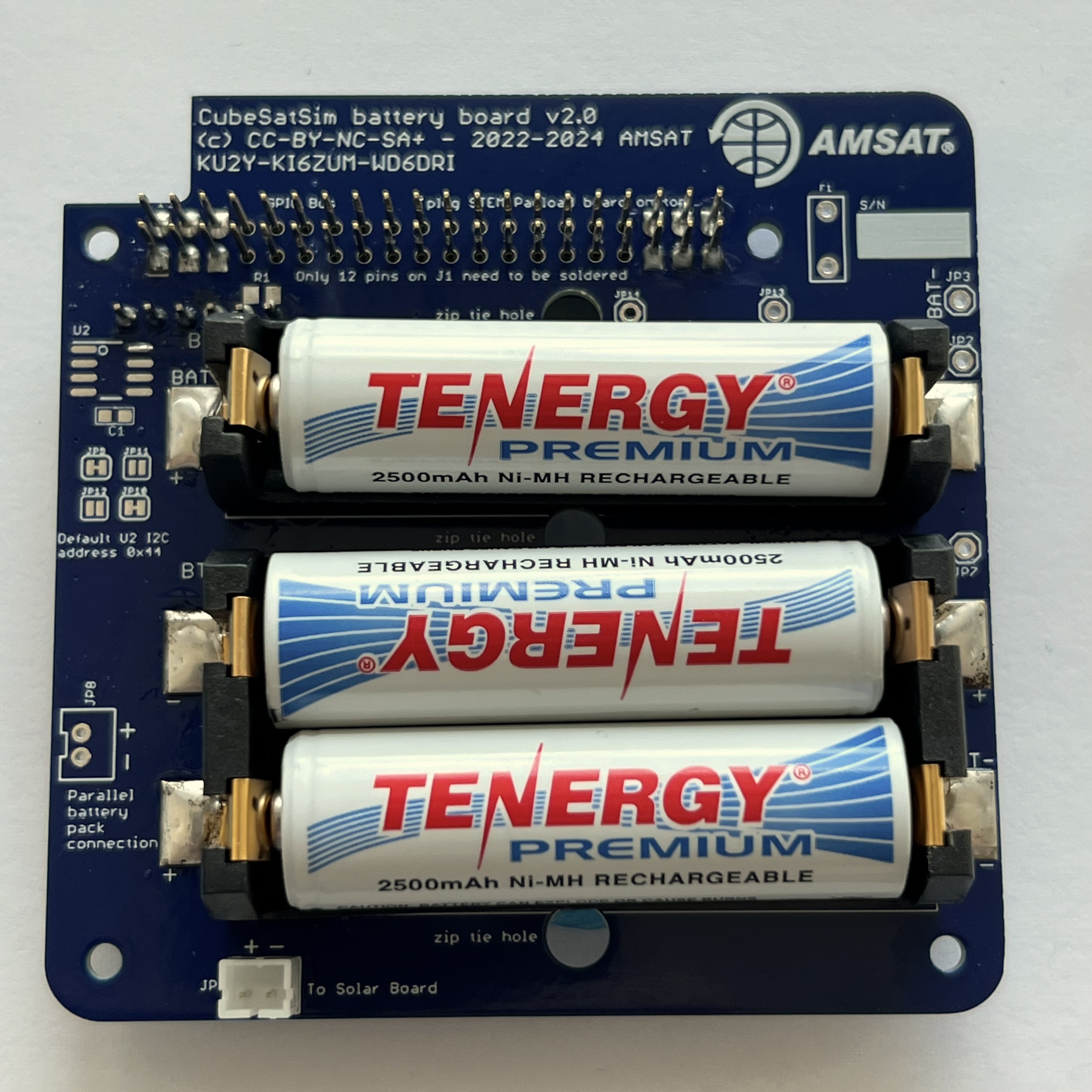
The three NiMH batteries can be inserted and held in place with the clips or zip ties.
First plug in the batteries, paying attention to the polarity:
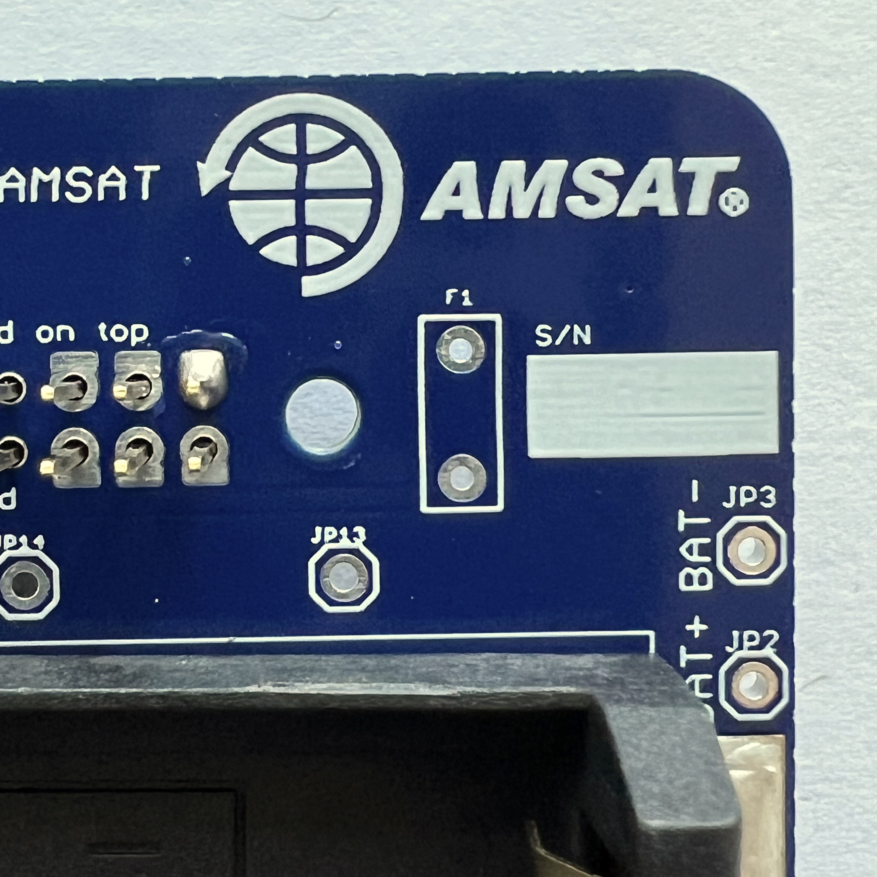
It is a good idea to test your battery polarity using a voltmeter. Use the BAT+ (J1) and BAT- (J2) test points on the board, being very careful not to short them together:
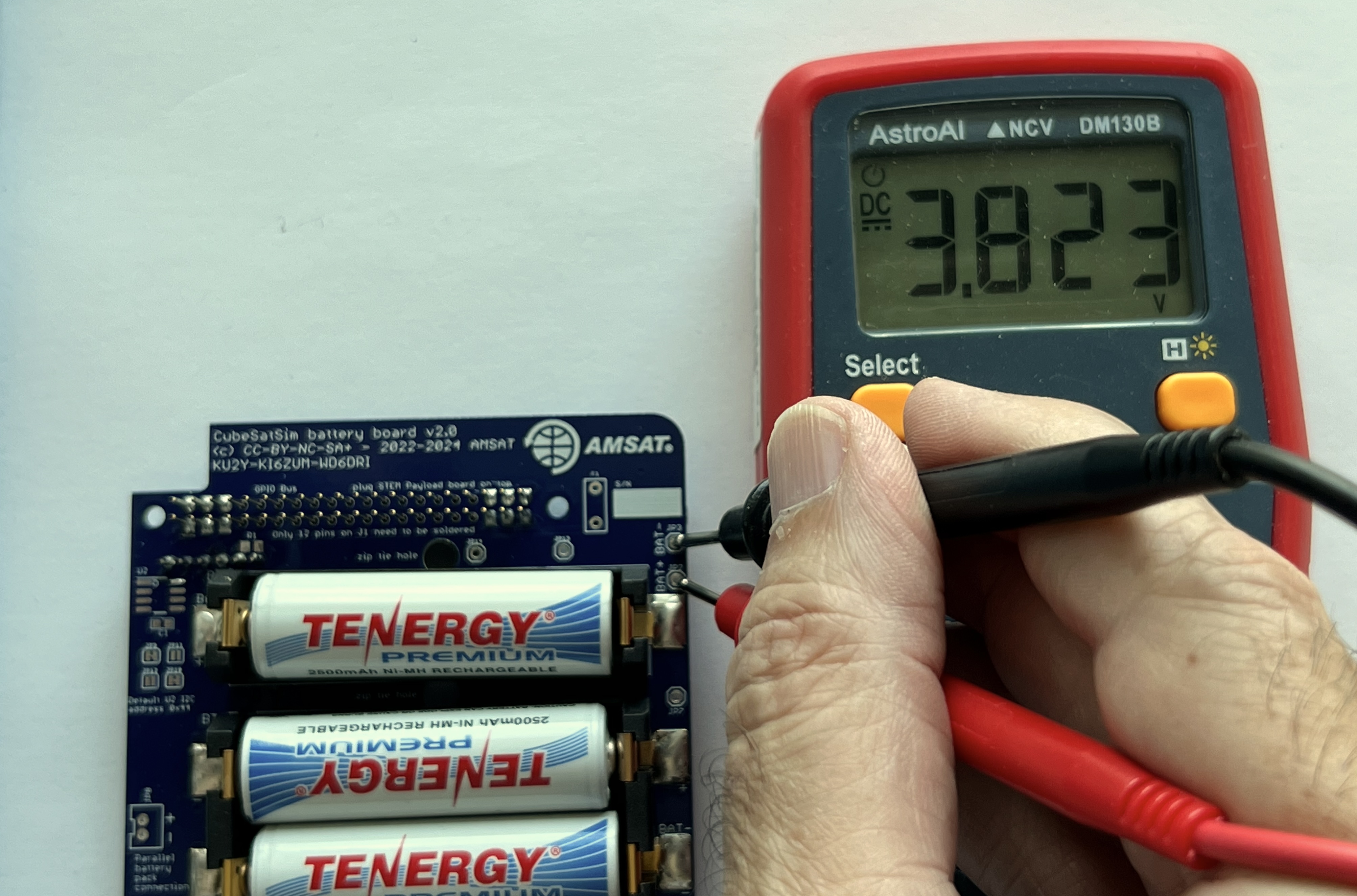
If you read a positive voltage in the range 3V - 4.5V, your Battery board is "nominal" and ready to be used. If you get a negative voltage, check that the red and black test leads are plugged into the positive and common inputs on your meter, or that your batteries aren't inserted backwards.
Secure the batteries with the clips. The clips need to be pushed down quite hard to get them to lock. This clip is not locked:
These clips are locked:
If you are using three single battery holders, only the top battery clip will work - you will need to zip tie the bottom two batteries:

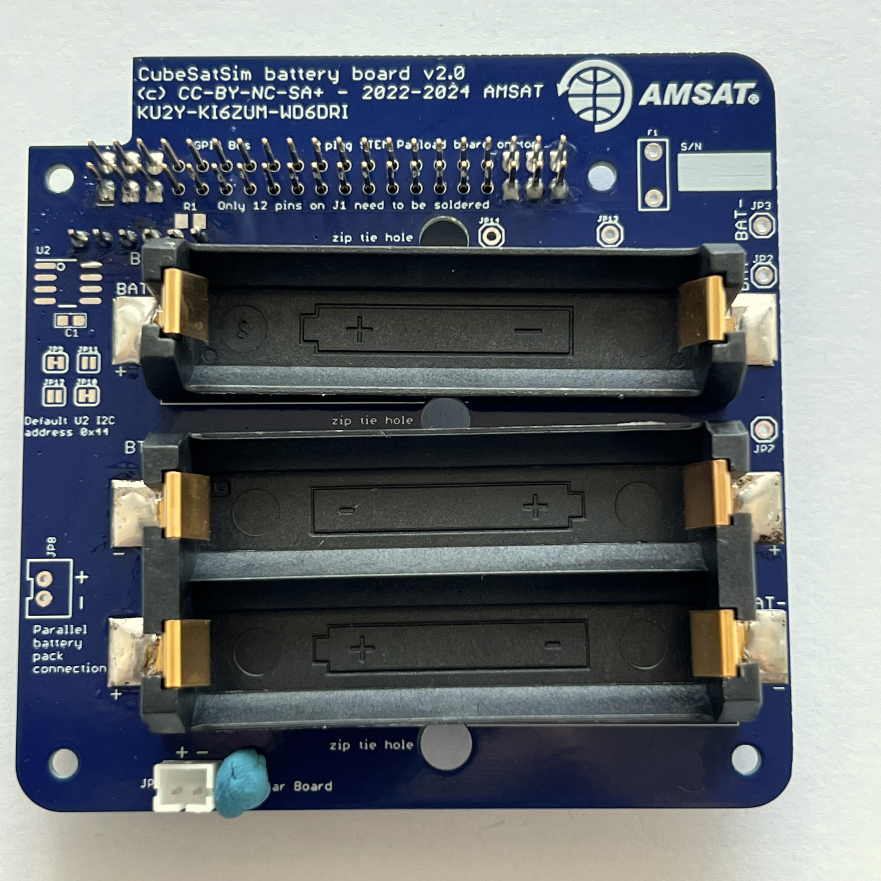
Here's how the completed board looks with the JST jumper wire connected to the JST connector:
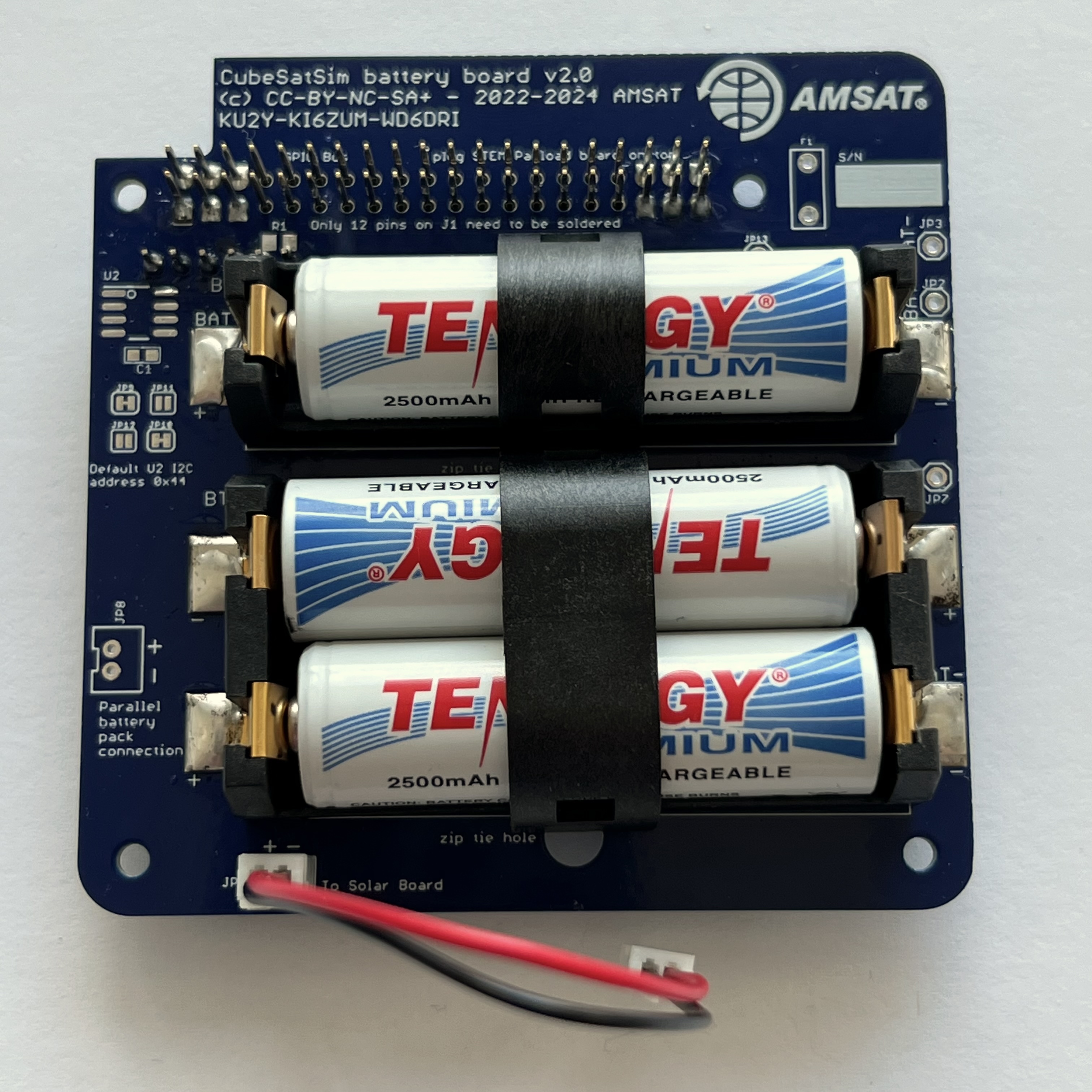
The next step is to assemble the Solar Board.