5. CONCEPT EVALUATION AND PRODUCT ARCHITECTURE - R-div-Engg-Exploration-2026-27-Odd/Repo-9 GitHub Wiki
This section organizes concept evaluation and product architecture for the semi-automatic mechanical clock.
Detailed pages:
- 5.1 Justifications for Score Given
- 5.2 Selected Design
- 5.3 Product Architecture
- 5.4 Function Clustering
- 5.5 Interaction Between Subsystems
Source workbook: ED3-CS
The workbook contains a weighted comparison and a separate score-justification exercise. Their criteria and design names differ; each is reproduced in its own context.
Recorded Objective Weights
Standalone weights from ED3-CS, Task 1. These are distinct from the Pugh chart’s weights.
| Objective | Weight |
|---|---|
| Safety | 9 |
| Ease of use | 7 |
| Portability | 5 |
| Use of standard parts | 6 |
| Cost | 6 |
Source: ED3-CS · C6:D11 ↗
Pugh Chart
The “Advanced geometry or Gear clock” is the datum. Symbols and totals below are reproduced from the workbook.
| Design objective | Weight | Advanced geometry or Gear clock | Pendulum or Escapement clock | Hydro mechanical clock | fan gear clock |
|---|---|---|---|---|---|
| simplicity of construction | 8 | datum | 0 | - | - |
| Timekeeping accuracy | 9 | datum | + | - | - |
| visibility of components | 5 | datum | + | ++ | 0 |
| aesthetics | 4 | datum | + | ++ | ++ |
| Mechanism smoothness | 7 | datum | 0 | - | - |
| Score(+) | — | 0 | 18 | 18 | 8 |
| Score (-) | — | 0 | 0 | -24 | -24 |
| Total | — | 0 | 18 | -6 | -16 |
Legend: datum = reference design; 0 = same as datum; + = better; ++ = much better; − = worse.
Source: ED3-CS · B15:G23 ↗
Arithmetic check. The recorded totals are consistent with multiplying weights by +1 for “+”, +2 for “++”, 0 for “0” and −1 for “−”. This yields 0, +18, −6 and −16, respectively.
5.1 Justifications for Score Given
The separate source exercise rates Pendulum, “Spring derive”, Weight driven and Balance. Its scores are recorded as given; a rating scale is not defined in the workbook.
Different design set. These are not the four alternatives named in the Pugh chart. The justifications therefore cannot be treated as direct explanations for every Pugh score. Cost figures below are source estimates, not a verified BOM.
1. Pendulum
Scores and recorded reasoning
| Objective | Score | Source justification |
|---|---|---|
| low cost | 4 | Simple parts about Rs. 1300 |
| Time accuracy | 4 | Pendulum keeps steady rhythm |
| Long durability | 4 | Few wearing parts |
| Easy assembly | 3 | Needs pendulum adjustment |
| Visual appeal | 4 | Classic wall design |
Source: ED3-CS · N5:Q9 ↗
2. Spring derive
Scores and recorded reasoning
| Objective | Score | Source justification |
|---|---|---|
| low cost | 4 | main spring about Rs. 1000 |
| Time accuracy | 3 | Drops as spring unwinds |
| Long durability | 3 | Spring fatigue over time |
| Easy assembly | 4 | Compact,fewerparts |
| Visual appeal | 4 | Neat, portal look |
Source: ED3-CS · N10:Q14 ↗
3. Weight driven
Scores and recorded reasoning
| Objective | Score | Source justification |
|---|---|---|
| low cost | 3 | frame about Rs. 1200 |
| Time accuracy | 5 | Constant force from weight |
| Long durability | 5 | Robust, Simple mechanism |
| Easy assembly | 2 | Needs height and rope setup |
| Visual appeal | 3 | Bulky, functional look |
Source: ED3-CS · N15:Q19 ↗
4. Balance
Scores and recorded reasoning
| Objective | Score | Source justification |
|---|---|---|
| low cost | 2 | Fine parts about Rs. 1500 |
| Time accuracy | 4 | Works in any position |
| Long durability | 3 | Delicate small parts |
| Easy assembly | 2 | Precision fitting needed |
| Visual appeal | 5 | Compact,elegant |
Source: ED3-CS · N20:Q24 ↗
“Spring derive”, “Neat, portal look” and other source wording are preserved as recorded.
5.2 Selected Design
Highest recorded Pugh score
Pendulum or Escapement clock
The leading alternative within the workbook’s Pugh comparison.
Weighted total: +18.
The Pugh chart favors the pendulum/escapement alternative over its datum and the other two alternatives. The workbook does not contain an explicit final selection or approval statement.
Selection status: not confirmed. The ED2 electronic/mechatronic concepts, ED3 Pugh alternatives and ED3 score-justification designs use different names and groupings. Their mapping needs clarification before the Pugh leader can be identified as the final project design.
Source: ED3-CS · B15:G23 ↗
Source: ED2-CD · B43:G51 ↗
5.3 Product Architecture
The source divides product operation into four subsystems.
| Subsystem | Source name |
|---|---|
| 1 | Display functions |
| 2 | User control function |
| 3 | Clock operation function |
| 4 | Alarm and Support Function |
Source: ED4-PA · H7:I11 ↗
5.4 Function Clustering
The original cluster diagram groups the clock’s functions into the four subsystems listed above.
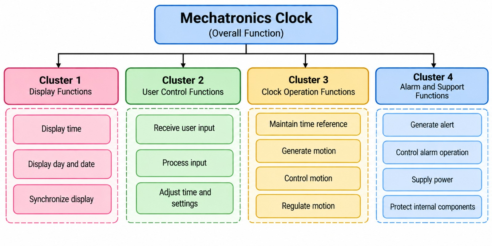
Original function clustering. Embedded source diagram, reproduced without alteration. ED4-PA · near A6 ↗
Text transcription of the original clustering diagram
| Cluster | Grouped functions |
|---|---|
| 1 · Display Functions | Display time; display day and date; synchronize display. |
| 2 · User Control Functions | Receive user input; process input; adjust time and settings. |
| 3 · Clock Operation Functions | Maintain time reference; generate motion; control motion; regulate motion. |
| 4 · Alarm and Support Functions | Generate alert; control alarm operation; supply power; protect internal components. |
5.5 Interaction Between Subsystems
Each source matrix records spatial, data and material interactions with the other subsystems.
Legend: ✓ = interaction marked in source; − = interaction not marked.
The source labels power/energy transfer as “Material”. That wording is preserved below.
Subsystem 1 · Display
Subsystem 1 interactions
| Interaction type | 2 User Control | 3 Clock Operation | 4 Alarm & Support | Interaction Details |
|---|---|---|---|---|
| Spatial | ✓ | ✓ | - | Physical arrangement |
| Data | ✓ | ✓ | ✓ | Information / signals |
| Material | - | - | ✓ | Power / energy |
Source: ED4-PA · K9:O12 ↗
Subsystem 2 · User Control
Subsystem 2 interactions
| Interaction type | 1 Display | 3 Clock Operation | 4 Alarm & Support | Interaction Details |
|---|---|---|---|---|
| Spatial | ✓ | ✓ | - | Physical arrangement |
| Data | ✓ | ✓ | ✓ | User commands |
| Material | - | - | ✓ | Power / energy |
Source: ED4-PA · K14:O17 ↗
Subsystem 3 · Clock Operation
Subsystem 3 interactions
| Interaction type | 1 Display | 2 User Control | 4 Alarm & Support | Interaction Details |
|---|---|---|---|---|
| Spatial | ✓ | ✓ | ✓ | Internal arrangement |
| Data | ✓ | ✓ | ✓ | Timing / control signals |
| Material | - | - | ✓ | Power / energy |
Source: ED4-PA · K19:O22 ↗
Subsystem 4 · Alarm & Support
Subsystem 4 interactions
| Interaction type | 1 Display | 2 User Control | 3 Clock Operation | Interaction Details |
|---|---|---|---|---|
| Spatial | - | - | ✓ | Physical arrangement |
| Data | ✓ | ✓ | ✓ | Alarm / status signals |
| Material | ✓ | ✓ | ✓ | Power / energy |
Source: ED4-PA · K24:O27 ↗