4. CONCEPT GENERATION - R-div-Engg-Exploration-2026-27-Odd/Repo-9 GitHub Wiki
This section organizes the concept-generation work for the semi-automatic mechanical clock.
Detailed pages:
Source workbook: ED2-CD
4.1 Establishing Functions
The source lists functions from the user’s and designer’s perspectives. Rows preserve the two source lists; their position does not establish a one-to-one mapping.
User and designer functions
| No. | Functions from user perspective | Functions from designer perspective |
|---|---|---|
| 1 | Read time | Display time |
| 2 | Adjust time | Process time setting |
| 3 | Set alarm | Maintain time reference |
| 4 | View clock movement | Detect position |
| 5 | Start or stop operation | Provide feedback |
| 6 | Maintain the clock | Synchronize display |
| 7 | — | Generate alert |
| 8 | — | Control alarm operation |
| 9 | — | Protect internal components |
| 10 | — | Support moving parts |
Source: ED2-CD · A5:C15 ↗
4.2 Function Tree
The original workbook diagram organizes the system under the title “Mechatronics Clock”. Select an image to view its full-size original.
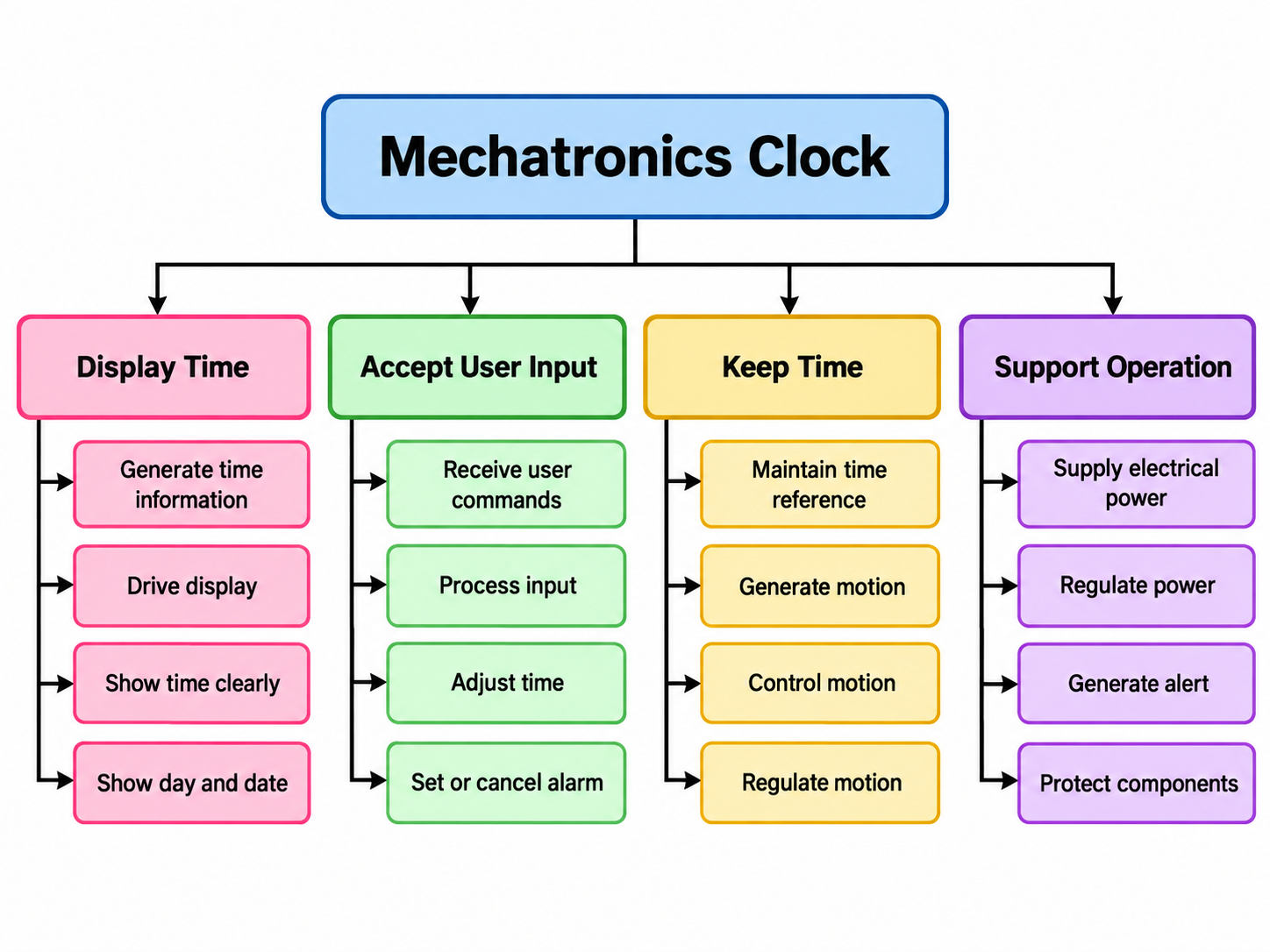
Original function tree. Embedded workbook diagram, reproduced without alteration. ED2-CD · near A57 ↗
Text transcription of the original function tree
| Branch | Functions |
|---|---|
| Display Time | Generate time information; drive display; show time clearly; show day and date. |
| Accept User Input | Receive user commands; process input; adjust time; set or cancel alarm. |
| Keep Time | Maintain time reference; generate motion; control motion; regulate motion. |
| Support Operation | Supply electrical power; regulate power; generate alert; protect components. |
4.3 Morphological Chart
Seven subfunctions with four alternative means for each. The table below preserves the workbook cells.
Alternative means — source cell table
| Subfunction | Means 1 | Means 2 | Means 3 | Means 4 |
|---|---|---|---|---|
| TIME DISPLAY | DC motor gear | Rotating LED display | LED clock hands | Analog clock hands |
| MOTION / ACTUATION | POV LED display | Servo motor | Stepper motor | Electromagnetic drive |
| CONTROLLER | Arduino Nano | Arduino Uno | ESP32 | ATmega328P |
| TIME KEEPING | RTC DS3231 | RTC DS1307 | Microcontroller timer | Internet / NTP time |
| POWER SUPPLY | 5V USB adapter | Rechargeable battery | AA battery pack | 12V adapter with regulator |
| POSITION SENSING | Hall-effect sensor | IR sensor | Optical interrupter | Rotary encoder |
| MOTION TRANSMISSION | Direct shaft drive | Crank-rocker mechanism | Gear train | Belt and pulley |
Source: ED2-CD · B30:G38 ↗
Two source versions differ. Cell D32 places “DC motor gear” under time display, and D33 places “POV LED display” under motion/actuation. The illustrated chart instead shows “POV LED display” and “DC motor with crank” in those positions. Both versions are available here.
Original illustrated morphological chart — includes the source’s alternative first-column labels
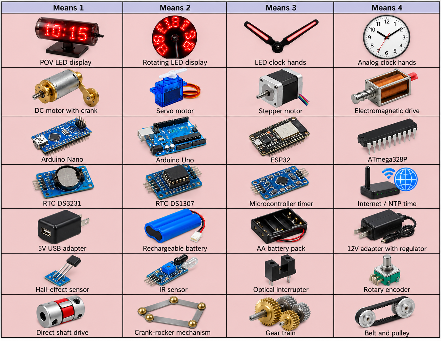
Original illustrated morphological chart. This embedded image differs from cells D32:D33 as noted above. ED2-CD · near C30 ↗
4.4 Generated Concepts
Four combinations are recorded in ED2-CD. “Design 1–4” below corresponds to that sheet’s “Concept 1–4” columns.
Source: ED2-CD · B43:G51 ↗
Design 1
- Time display: POV LED display
- Motion / actuation: DC motor with crank
- Controller: Arduino Nano
- Time keeping: RTC DS3231
- Power supply: 5V USB adapter
- Position sensing: Hall-effect sensor
- Motion transmission: Crank-rocker mechanism
Source: ED2-CD · D45:D51 ↗
Design 2
- Time display: Rotating LED display
- Motion / actuation: Stepper motor
- Controller: Arduino Uno
- Time keeping: RTC DS1307
- Power supply: Rechargeable battery
- Position sensing: IR sensor
- Motion transmission: Direct shaft drive
Source: ED2-CD · E45:E51 ↗
Design 3
- Time display: LED clock hands
- Motion / actuation: Servo motor
- Controller: ESP32
- Time keeping: Internet / NTP time
- Power supply: 12V adapter with regulator
- Position sensing: Rotary encoder
- Motion transmission: Gear train
Source: ED2-CD · F45:F51 ↗
Design 4
- Time display: Analog clock hands
- Motion / actuation: Electromagnetic drive
- Controller: ATmega328P
- Time keeping: Microcontroller timer
- Power supply: AA battery pack
- Position sensing: Optical interrupter
- Motion transmission: Belt and pulley
Source: ED2-CD · G45:G51 ↗
Source numbering. The concept matrix repeats serial number 1 for its second row. All seven subfunctions are preserved above. These four concepts are not reliably mapped to the differently named alternatives in the Pugh chart.
Source Drawing Gallery
Four original clock drawings embedded in ED3-CS. Their mapping to the numbered concepts or Pugh alternatives is not stated, so they are presented as independent source drawings.
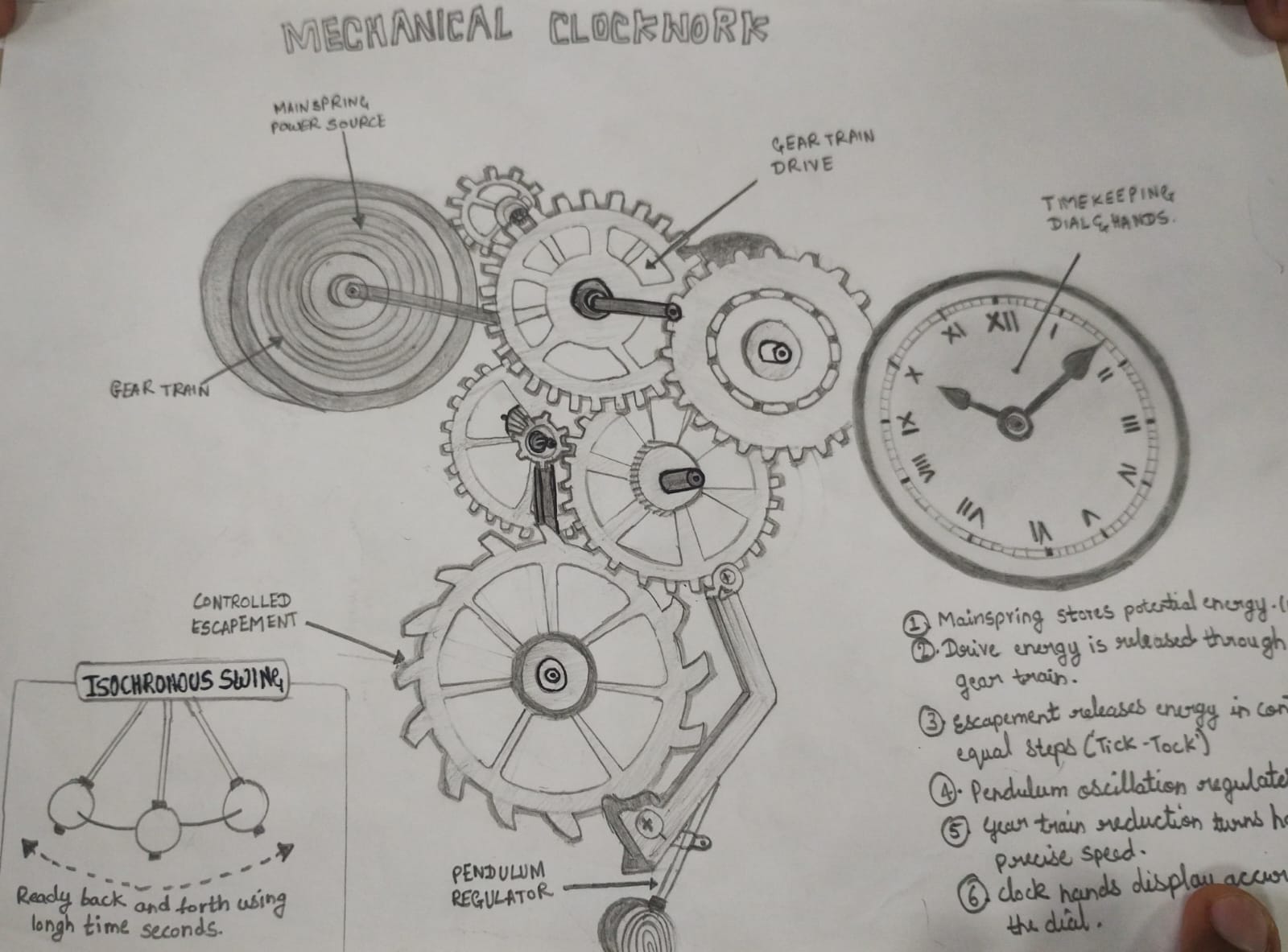
Mechanical Clockwork. Original photographed sketch. Some handwritten text is cropped in the source. ED3-CS · near A25 ↗
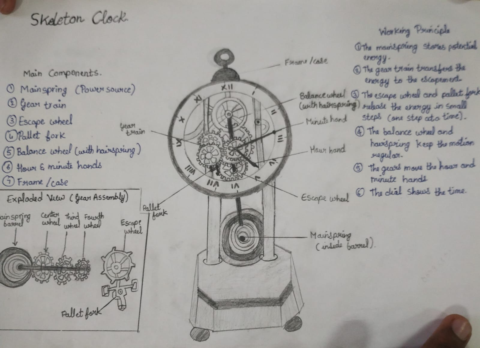
Skeleton Clock. Original drawing with component labels and working-principle notes. ED3-CS · near A50 ↗
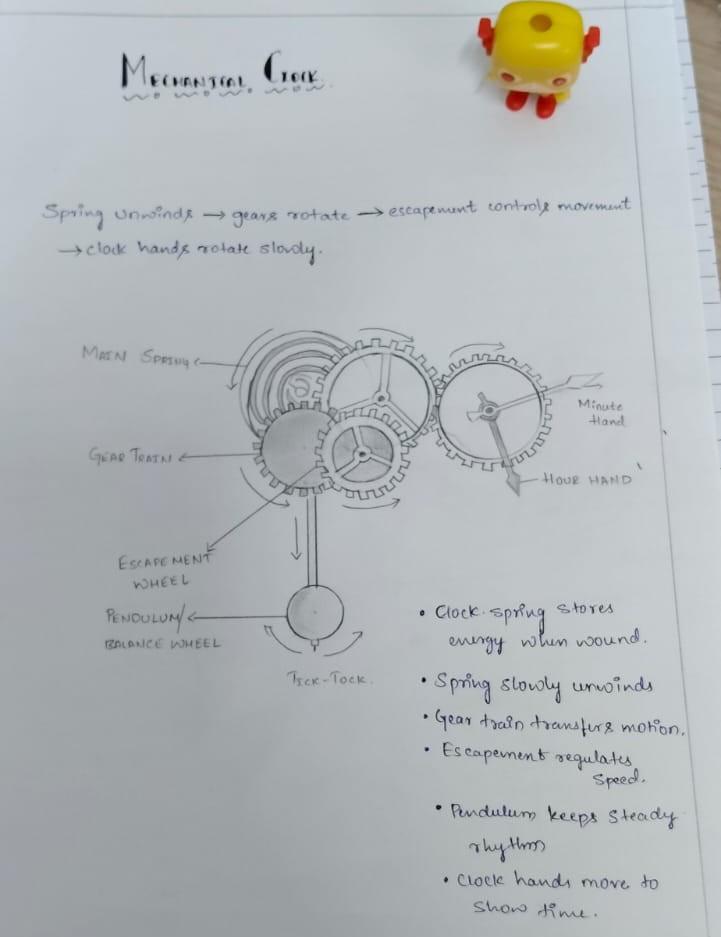
Mechanical Clock. Original drawing showing the progression from spring unwinding to hand motion. ED3-CS · near A86 ↗
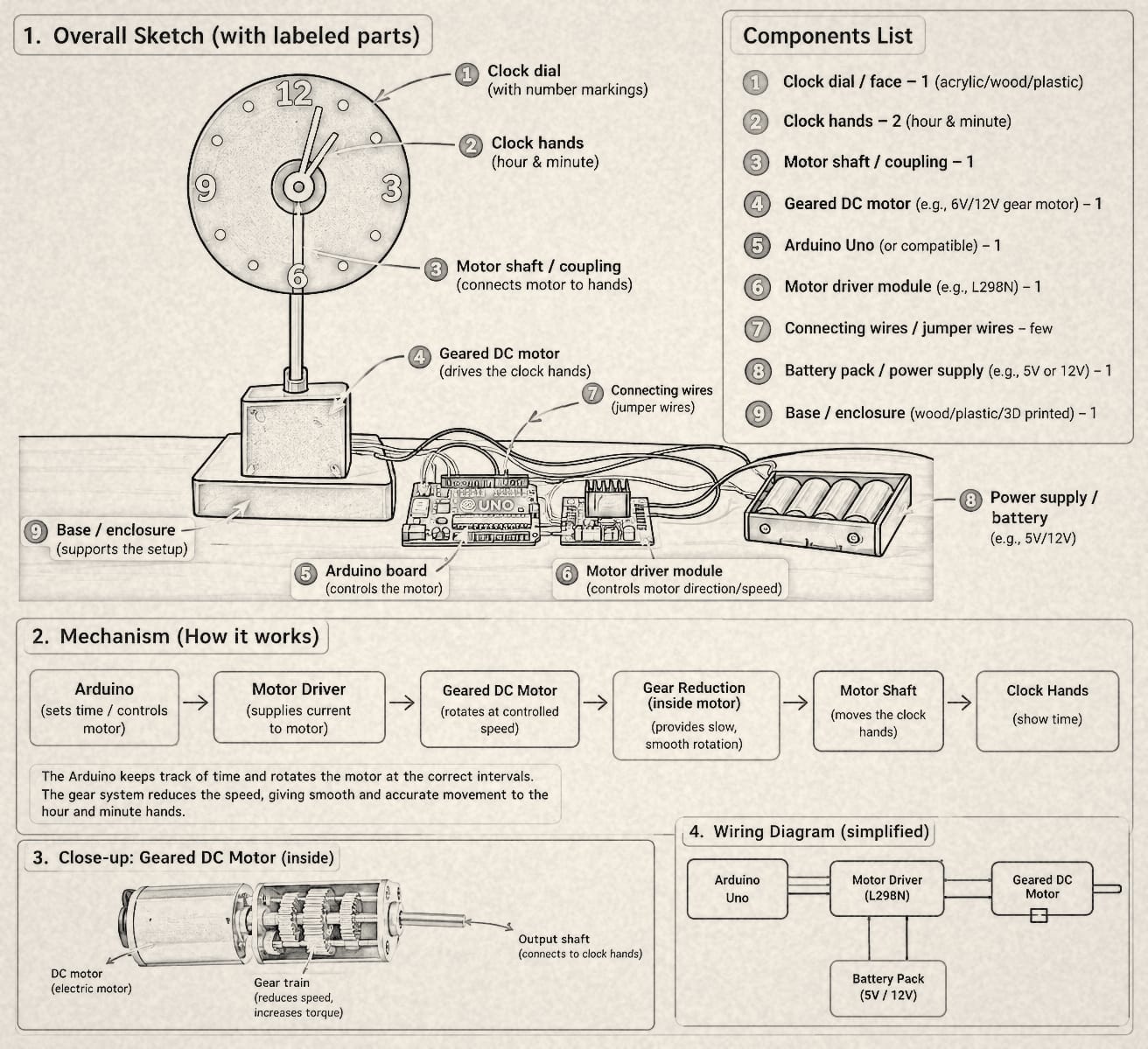
Motor clock design. Original schematic with illustrative components and wiring; it is not a completed bill of materials. ED3-CS · near D40 ↗