Troubleshooting - PiSCSI/piscsi GitHub Wiki
Schematics for the PiSCSI Reloaded are available in pdf format. Choose the one that corresponds to the hardware revision of your particular board.
First step in troubleshooting is to check the termination. Seriously. Check this.
https://lowendmac.com/1998/termination-explained/
Re-check it again.
A way to check out the PiSCSI hardware is to create a loopback cable. This can be done using jumper wires or a specially-constructed DB25 male jack connector can be created to allow easy re-use.

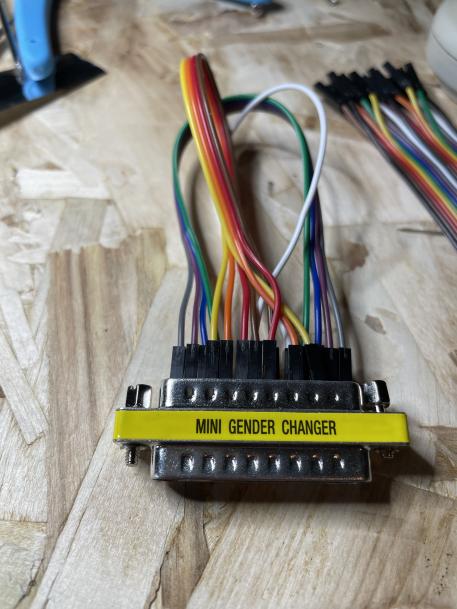
The diagram for the loopback connections is shown here. Note that the PiSCSI connector is a FEMALE connector. If you are using a gender changer (as in the previous picture), you want to use the MALE connector pinout
FEMALE connector pinout 
|
MALE connector pinout 
|
Once you have the loopback connections made, you can checkout the PiSCSI source code and run the loopback test python script. (Note: This requires python3 to run)
Before running this test:
- Ensure that you have termination enabled before running this test!!
- Ensure that the PiSCSI service is NOT running `sudo systemctl stop piscsi`
- Double check your loopback that you do NOT have TERM POWER connected to Ground!!!

Starting with PiSCSI version 22.12, the loopback test application was re-written in C++. Either version will work, but the Python version may be deleted in the future.
| "New" C++ Version (PiSCSI Version 22.12 and later) | "Old" Python Version |
|---|---|
| The C++ version (called scsiloop) should already be installed. To run it, use the following command: `sudo scsiloop` |
If you don't already have PiSCSI checked out:
|
| The utility will list all of the SCSI signals that are not working properly. You can the use the schematic to debug if there are any broken traces, lifted pads or bad solder joints. | The Python test script will list all of the SCSI signals that are not working properly. You can the use the schematic to debug if there are any broken traces, lifted pads or bad solder joints. |
Example of a mostly successful test run
 Example of a completely failed test run

|
Example Successful Test Run
 Example Test Run With Failures
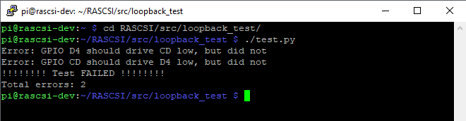 In this case, there is something wrong with either the "C/D" SCSI signal or the "D4" SCSI data line or both.
|
Note: this concept was original created by Saybur for the Scuznet board: https://github.com/saybur/scuznet/tree/master/testing
You can test each individual SCSI signal using a multimeter. This procedure is listed here.
Turn on the termination DIP switches
Pull out your trusty multimeter. With the PiSCSI software running, disconnect all SCSI devices and check the voltages:
- TPWR should be 5v
- D0-D7 should be around 3.08v
- Control signals should be around 3.08v
- Check the LEDS
 raspi-gpio set 4 op dh #  ACT LED should be ON
 raspi-gpio set 4 op dl #  ACT LED should be OFF
 raspi-gpio set 5 op dh #  ENB LED should be ON
 raspi-gpio set 5 op dl #  ENB LED should be OFF
- Set the direction of the transceivers to be outputs
 raspi-gpio set 8 op dl #PI-DTD is GPIO 8 - set LOW for Pi->SCSI output
 raspi-gpio set 6 op dh #PI-IND is GPIO 6 - set HIGH for Pi->SCSI output
 raspi-gpio set 7 op dh #PI-TAD is GPIO 7 - set HIGH for Pi-SCSI output
- Check Data 0
 raspi-gpio set 10 op dh # D0 output should be around 3v
 raspi-gpio set 10 op dl # D0 output should be around 0v
- Repeat for all of the other data and control signals
 raspi-gpio set <GPIO> op dh # <Signal> output should be around 3v
 raspi-gpio set <Signal> op dl # <Signal> output should be around 0v
| Signal | GPIO | Direction Control | Direction: Pi->SCSI | Direction: SCSI->PI |
| D0 | 10 | DTD (GPIO 8) |
raspi-gpio set 8 op dl
|
raspi-gpio set 8 op dh
|
| D1 | 11 | DTD (GPIO 8) |
raspi-gpio set 8 op dl
|
raspi-gpio set 8 op dh
|
| D2 | 12 | DTD (GPIO 8) |
raspi-gpio set 8 op dl
|
raspi-gpio set 8 op dh
|
| D3 | 13 | DTD (GPIO 8) |
raspi-gpio set 8 op dl
|
raspi-gpio set 8 op dh
|
| D4 | 14 | DTD (GPIO 8) |
raspi-gpio set 8 op dl
|
raspi-gpio set 8 op dh
|
| D5 | 15 | DTD (GPIO 8) |
raspi-gpio set 8 op dl
|
raspi-gpio set 8 op dh
|
| D6 | 16 | DTD (GPIO 8) |
raspi-gpio set 8 op dl
|
raspi-gpio set 8 op dh
|
| D7 | 17 | DTD (GPIO 8) |
raspi-gpio set 8 op dl
|
raspi-gpio set 8 op dh
|
| DP | 18 | DTD (GPIO 8) |
raspi-gpio set 8 op dl
|
raspi-gpio set 8 op dh
|
| I/O | 25 | TAD (GPIO 7) |
raspi-gpio set 7 op dh
|
raspi-gpio set 7 op dl
|
| REQ | 22 | TAD (GPIO 7) |
raspi-gpio set 7 op dh
|
raspi-gpio set 7 op dl
|
| C/D | 24 | TAD (GPIO 7) |
raspi-gpio set 7 op dh
|
raspi-gpio set 7 op dl
|
| MSG | 23 | TAD (GPIO 7) |
raspi-gpio set 7 op dh
|
raspi-gpio set 7 op dl
|
| BSY | 26 | TAD (GPIO 7) |
raspi-gpio set 7 op dh
|
raspi-gpio set 7 op dl
|
| SEL | 27 | IND (GPIO 6) |
raspi-gpio set 6 op dh
|
raspi-gpio set 6 op dl
|
| RST | 20 | IND (GPIO 6) |
raspi-gpio set 6 op dh
|
raspi-gpio set 6 op dl
|
| ACK | 21 | IND (GPIO 6) |
raspi-gpio set 6 op dh
|
raspi-gpio set 6 op dl
|
| ATN | 19 | IND (GPIO 6) |
raspi-gpio set 6 op dh
|
raspi-gpio set 6 op dl
|
SCSI is sensitive to cable length and cabling quality issues. If you are experiencing failures with certain operations in your sampler, try using a shorter cable! Note that failures may not necessarily show up as errors in the PiSCSI logs, since it might be sending messages perfectly fine that are being lost in transit.
Each SCSI device has an ID assigned, and that ID needs to be unique. If an ID is shared, the host system may behave erratically, and often only see one of the devices that share an ID.
Make sure that the SCSI devices that you attach with PiSCSI do not have conflicting IDs with any other SCSI device on the chain (if any.) For instance, the internal SCSI hard drive on Macs usually has ID0 assigned, so avoid this in case your Mac has an internal hard drive.
The SCSI host often has a dedicated ID for itself that you should never use with attached devices. On Macs, that is ID7. Other platforms may use a different one.
If your host system supports LUNs (Logical Unit Numbers) then multiple devices can share the same ID as long as they have different LUNs. This is a rare occurrence in consumer computers.
If you see an error like the following, your Raspberry Pi OS may be too old.
log.h:22:3: error: ‘log’ is not a member of ‘spdlog’
   spdlog::log(loglevel,buf);}while(0);
The easiest approach would be to generate a new SD card with the latest version of Raspberry Pi OS, using the Raspberry Pi Imager (https://www.raspberrypi.org/software/). You can also try to update libspdlog-dev to a newer version.
You can check which version of spdlog you're using with the following command:
pi@rascsi:~ $ sudo apt search libspdlog
Sorting... Done
Full Text Search... Done
libspdlog-dev/stable,now 1:1.3.1-1+rpi1 armhf [installed]
  Very fast, header only, C++ logging library

pi@rascsi:~ $You may find that the network interface that your Pi is using to connect to your LAN and the internet keeps getting pulled down and restarted, causing temporary connectivity interruptions. While the root cause is not known at the time of writing, a workaround that has been proven effective is to disable network interfaces that you don't actively use, e.g. wlan and bluetooth if you're using eth.
This can be achieved by appending the following to the bottom of /boot/config.txt and rebooting your Pi (for disabling wlan and bluetooth):
dtoverlay=disable-bt
dtoverlay=disable-wifiIf your PiSCSI setup is starting up but behaving erratically, it may not be getting enough power from the power supply or SCSI bus. Symptoms include the network interface going down randomly, the SCSI host not recognizing attached devices due to lack of termination power, or bus errors on the host system caused by the emulated SCSI device.
One way to determine that the Raspberry Pi isn't getting enough power, is to observe the syslog and look for "Under-voltage detected!" messages.
It is recommended to use a known good power supply rated for at least 5V / 2.5 amps -- maybe even higher for overclocked or more powerful future generations of Raspberry Pis.
The PiSCSI Web Interface, OLED script, and Control Board script have in common that they're written in Python. The vast majority of issues with them stem from missing Python libraries, or a corrupted Python virtual environment (venv). In the logs, you will see messages complaining about missing Python libraries such as "bjoern". Here are a few tips for resolving Python runtime issues.
- Make sure you have at least Python 3.7 installed on your system. Older versions aren't supported.
- Make sure the RPi has internet connectivity while installing piscsi software. The script will download libraries from remote repositories.
- Re-run the "Web Interface stand-alone", "OLED" or "Control Board" installation options in easyinstall.sh. This will attempt to cache the Python libraries again.
- Remove the "venv" dir for the piscsi-web app and restart it. Example for the Web Interface below. Substitute "web" for "oled" or "ctrlboard" as needed.
$ sudo systemctl stop piscsi-web
$ cd ~/piscsi/python/web
$ sudo rm -rf venv
$ sudo systemctl start piscsi-web