Pneumatics - MDHSRobotics/TeamWiki GitHub Wiki
Pneumatics
Solenoids
General Information
Solenoid Valves are electromagnetically operated valve. Depending on how many ports there are, the wiring may vary; however, they act like a switch, they have ground and a 12 volt (24 on some, check the manual). By running the wires with 12 volts, the state changes. Turing on would let out air on one valve, and turning off the current turns on another valve. This is useful for controlling pistons as one they have two states: extend and retract.
Labels of Valves
On the solenoids, there is a chart on it which has the flow of air (for the most part, we will be using a 5 port solenoid which basically has two states of air flow). On one side, there are two valves which are labeled: A and B. On the bottom, there are three valves which are labeled: R, P, and S. The input valve is the P port, and the output valve is found in port A and B. Port R and S are exhaust ports which should automatically release pressure at 115 psi (I could be wrong, but check the manual).
Wiring
By opening up the circuit board (please use the manual and know how to put it back together) you will find two pins on top and one pin on the bottom. The top pins are labeled 1 and 2, however the bottom is not labeled. This is where we spent 2 weeks on this figuring it out. The bottom is also ground! Base ground used as a safety in case of a power surge. But when it comes to wiring, you can either wire it to ground, or just leave it out (at least try to wire it so we don't waste 50 dollars on another solenoid).
Example Wiring from 2017 Season
//Extra Resources
http://library.automationdirect.com/pneumatic-circuit-symbols-explained/ https://drive.google.com/drive/folders/0B0pRNh4PO0T_cFBDSGo2bVZaY1E https://stcvalve.com/STC-DOWNLOAD/SOP-2V025.pdf
Pictures


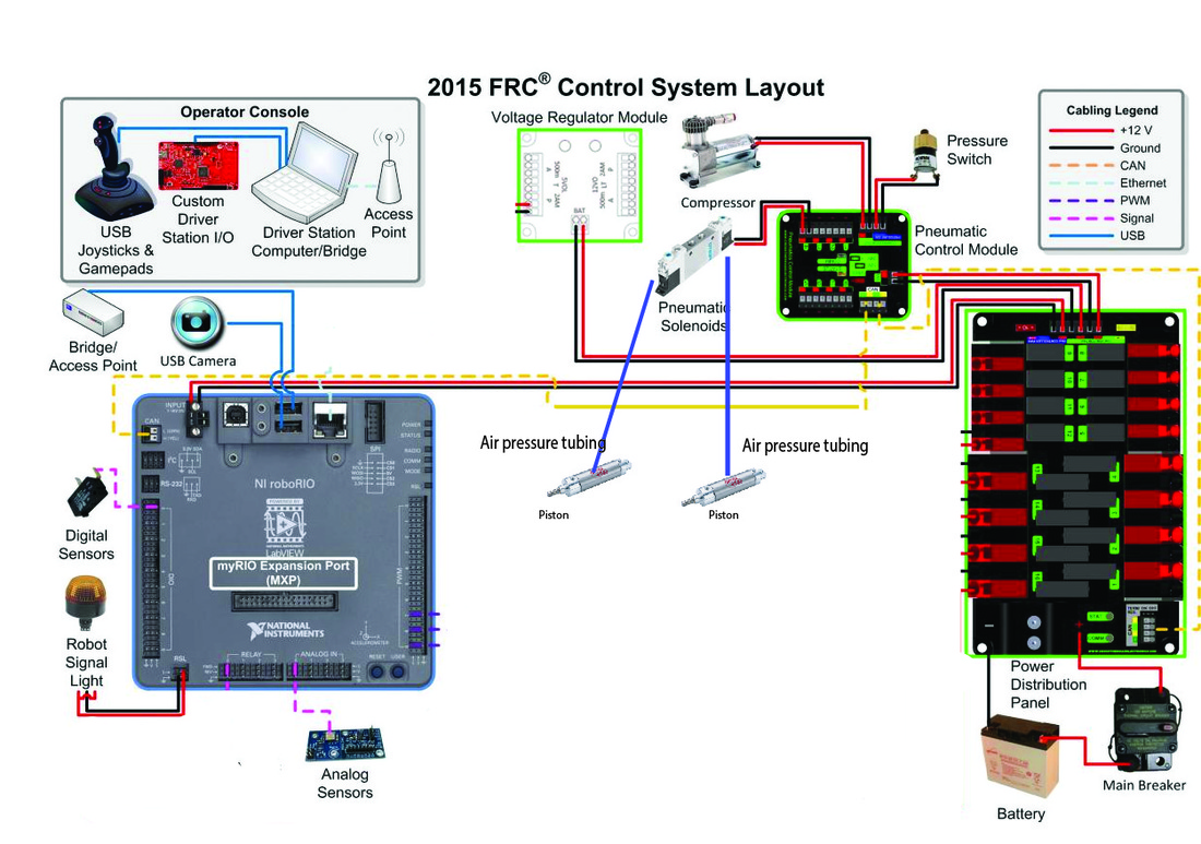
Overview
General Information
Solenoid Valves are electromagnetically operated valve. Depending on how many ports there are, the wiring may vary; however, they act like a switch, they have ground and a 12 volt (24 on some, check the manual). By running the wires with 12 volts, the state changes. Turing on would let out air on one valve, and turning off the current turns on another valve. This is useful for controlling pistons as one they have two states: extend and retract.
Solenoids
Labels of Valves On the solenoids, there is a chart on it which has the flow of air (for the most part, we will be using a 5 port solenoid which basically has two states of air flow). On one side, there are two valves which are labeled: A and B. On the bottom, there are three valves which are labeled: R, P, and S. The input valve is the P port, and the output valve is found in port A and B. Port R and S are exhaust ports which should automatically release pressure at 115 psi (I could be wrong, but check the manual).
Wiring
By opening up the circuit board (please use the manual and know how to put it back together) you will find two pins on top and one pin on the bottom. The top pins are labeled 1 and 2, however the bottom is not labeled. This is where we spent 2 weeks on this figuring it out. The bottom is also ground! Or at leas base ground used as a safety in case of a power surge. But when it comes to wiring, you can either wire it to ground, or just leave it out (at least try to wire it so we don't waste 50 dollars on another solenoid).
//Extra Resource on Drive
http://library.automationdirect.com/pneumatic-circuit-symbols-explained/://drive.google.com/drive/folders/0B0pRNh4PO0T_cFBDSGo2bVZaY1E https://stcvalve.com/STC-DOWNLOAD/SOP-2V025.pdf
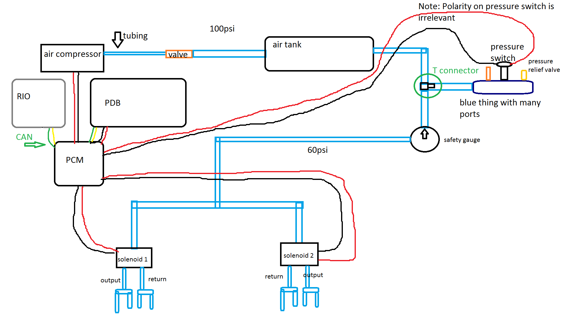
Pneumatics Diagram
Everything you need to know
(https://firstfrc.blob.core.windows.net/frc2017/pneumatics-manual.pdf)