TensorFlow for Blocks - FIRST-Tech-Challenge/SkyStone GitHub Wiki
FTC robots have many ways to autonomously navigate the game field. This tutorial introduces TensorFlow Lite, a software tool that can identify and track certain game elements as 3D objects. TensorFlow Lite uses input from Vuforia, a software tool (described in a separate tutorial) that processes 2D camera images.
These two tools combine several high-impact technologies: vision processing, machine learning, and autonomous navigation. Awareness of this software can spark further interest and exploration by FTC students as they prepare for future studies and careers in high technology.
TensorFlow Lite is a lightweight version of Google's TensorFlow machine learning technology that is designed to run on mobile devices such as an Android smartphone. Support for TensorFlow Lite was introduced to FTC in 2018. For the 2019-2020 FTC game, SKYSTONE, a trained inference model was developed to recognize the Stone and Skystone game pieces.
This Tensorflow inference model has been integrated into the FTC software and can be used to identify and track these game pieces during a match. The software can report the object’s location and orientation relative to the robot’s camera. This allows autonomous navigation, an essential element of modern robotics.
The TensorFlow Lite technology for object detection works on all FTC approved phones except the ZTE Speed. TensorFlow Lite requires Android 6.0 (Marshmallow) or higher. The REV Expansion Hub and REV Control Hub both support using this technology.
For Blocks programmers using an older Android phone that is not running Marshmallow or higher, the TensorFlow Object Detection (TFOD) category of Blocks will automatically be missing from the Blocks design palette.
This tutorial describes the Op Modes provided in the FTC Blocks sample menu for TensorFlow Object Detection (TFOD).
On a laptop connected via Wifi to the Robot Controller (RC) phone or REV Control Hub, at the Blocks screen, click Create New Op Mode. Type a name for your example program, and choose the appropriate TensorFlow sample. If using the RC phone’s camera, choose the first Sample shown below.

If using a webcam, with REV Expansion Hub or REV Control Hub, choose the second Sample.

Then click OK to enter the programming screen.
Your new Op Mode will appear on the Blocks programming screen, including the Blocks needed for TensorFlow Object Detection (TFOD).

This Op Mode has a simple structure. The first section of Blocks is the main program, followed by one function. A function is a named collection of Blocks to do a certain task. This organizes and reduces the size of the main program, making it easier to read and edit. In Java these functions are called methods.
This program shows various Blocks for basic use of TensorFlow. Other related Blocks can be found in the TensorFlow Object Detection folder, under the Utilities menu at the left side.

The heading ‘Optimized for SKYSTONE’ contains many of the game-specific Blocks in this sample. The other heading 'Recognition' provides a variety of available TFOD variables or data fields.
Using TensorFlow requires the background use of Vuforia, because they work together to provide TFOD results.
The first section of an Op Mode is called initialization. These commands are run one time only, when the INIT button is pressed on the Driver Station (DS) phone. Besides the Telemetry messages, this section has only three actions: initialize Vuforia (specify its settings), initialize TFOD (specify its settings), and activate TFOD (turn it on). This "init" section ends with the command waitForStart.
The first Block initiates Vuforia, which will provide the camera's image data to TensorFlow.

When using the RC phone camera, the FTC Vuforia software has 11 available settings to indicate your preferred usage and the camera’s location. Set Camera Monitoring to false; the Vuforia display is not needed since TensorFlow offers its own monitoring display. If you definitely want to also monitor Vuforia, try setting this to true; some RC phones have trouble displaying both videos together.
This example uses the phone’s BACK camera, requiring the phone to be rotated -90 degrees about its long Y axis. For this sample Op Mode, the RC phone is used in Landscape mode.
Important Note: Although the phone rotation values are important if you are planning to use the Vuforia software for image detection and tracking, these rotation values are not used by the TensorFlow software. TensorFlow only uses the Vuforia software to provide the stream of camera images. When using TensorFlow, it is more important that when you initialize the TensorFlow library, the camera is oriented in the mode (portrait or landscape) that you want to use during your op mode run (see the section entitled Important Note Regarding Image Orientation below).
When using a webcam, Vuforia has 12 available settings. The RC cameraDirection setting is replaced with two others related to the webcam: its configured name, and an optional calibration filename.
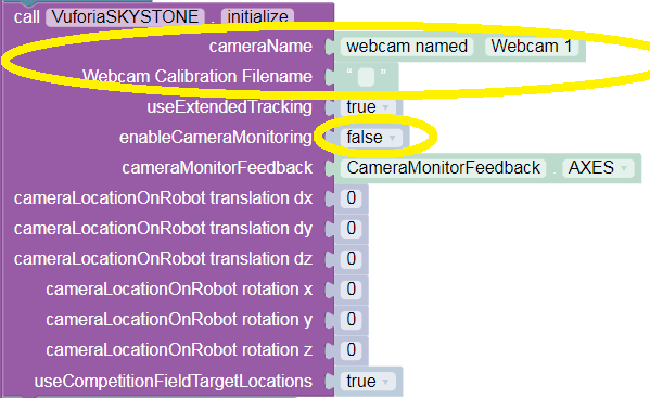
Also for webcams, set ‘Camera Monitoring’ to false; the Vuforia display is not needed since TensorFlow offers its own monitoring display. If you definitely want to also monitor Vuforia, try setting this to true; some RC phones have trouble displaying both videos together.
For Control Hubs, ‘Camera Monitoring’ would enable display on an external monitor or video device plugged into the HDMI port (not allowed in competition).
If ‘Camera Monitoring’ is used, the ‘Feedback’ setting can display AXES, showing Vuforia’s X, Y, Z axes of the reference frame local to the image.
‘Translation’ and 'rotation' specify the phone’s position and orientation on the robot. These allow Vuforia-specific navigation and are not used for TensorFlow Object Detection (TFOD).
The next Block initializes the TFOD software.

The key setting is the minimum Confidence, the minimum level of certainty required to declare that a trained object has been recognized in the camera's field of view. A higher value (but under 100%) causes the software to be more selective in identifying a trained object, either a Stone or a Skystone for the 2019-2020 FTC game. Teams should adjust this parameter for a good result based on distance, angle, lighting, surrounding objects, and other factors.
Note that for the 2019-2020 FTC Game, people have reported that using a lower confidence threshold (on the order of 50% or so) results more accurate detections when the game elements (Stones and Skystones) are placed side-by-side.
The Object Tracker parameter set to true means the software will use an object tracker in addition to the TensorFlow interpreter, to keep track of the on-screen locations of detected objects. The object tracker interpolates object recognitions for results that are smoother than using only the TensorFlow interpreter.
The Camera Monitoring parameter opens a camera preview window on the RC phone, or enables a webcam preview through the Control Hub's HDMI port on an external monitor or device (not allowed in competition). This video preview shows the camera or webcam image with superimposed TensorFlow data, including bounding boxes for detected objects.

A static preview is also available on the DS screen, with the REV Expansion Hub and the REV Control Hub. To see it, choose the main menu’s Camera Stream when the Op Mode has initialized (but not started). Touch to refresh the image as needed, and select Camera Stream again to close the preview and continue the Op Mode. This is described further in the tutorial Using an External Webcam with Control Hub.

In the TensorFlow camera monitor window, the confidence level for a detected target appears near the bounding box of the identified object (when Object Tracker is enabled). For example, a value of 0.95 indicates a 95% confidence that the object has been identified correctly.
The origin of the coordinate system is in the upper left corner of the image. The horizontal (X) coordinate value increases when moving from left to right. The vertical (Y) coordinate value increases when moving from top to bottom.

When an object is identified by TensorFlow, the FTC software can provide 'Left', 'Right', 'Top' and 'Bottom' variables associated with the detected object. These values, in units of pixel coordinates, indicate the location of the left, right, top and bottom boundaries of the detection box for that object.
This and other information about the detected object can be used to navigate towards the object, such as a Stone or Skystone. The values are available from the Blocks menu, under the Recognition submenu described above. This robot driving action is not part of the sample Op Mode, but is described below in "Navigation Example".
The system interprets images based on the phone's orientation (Portrait or Landscape) at the time that the TensorFlow object detector was created and initialized. In our example, if you execute the TensorFlowObjectDetection.initialize block while the phone is in Portrait mode, then the images will be processed in Portrait mode.

If you initialize the detector in Portrait mode, then the images are processed in Portrait mode.
The "Left" and "Right" values of an object's bounding box correspond to horizontal coordinate values, while the "Top" and "Bottom" values of an object's bounding box correspond to vertical coordinate values.
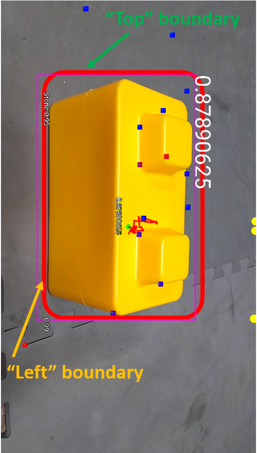
The "Left" and "Top" boundaries of a detection box when the image is in Portrait mode.
If you want to use your smartphone in Landscape mode, then make sure that your phone is in Landscape mode when the TensorFlow object detector is initialized.

The system can also be run in Landscape mode.
If the phone is in Landscape mode when the object detector is initialized, then the images will be interpreted in Landscape mode.

The "Left" and "Top" boundaries of a detection box when the image is in Landscape mode.
Note that Android devices can be locked into Portrait Mode so that the screen image will not rotate even if the phone is held in a Landscape orientation. If your phone is locked in Portrait Mode, then the TensorFlow object detector will interpret all images as Portrait images. If you would like to use the phone in Landscape mode, then you need to make sure your phone is set to "Auto-rotate" mode. In Auto-rotate mode, if the phone is held in a Landscape orientation, then the screen will auto rotate to display the contents in Landscape form.
For webcam users, the images should be provided in landscape mode.

Auto-rotate must be enabled in order to operate in Landscape mode.
Lastly, in the main program’s initialization section, there remains only the command to activate TensorFlow Object Detection (TFOD).

This starts the TensorFlow software and opens or enables the Monitoring images if specified. It also enables the static preview on the DS phone. The REV Control Hub offers a video feed only through its HDMI port, not allowed during competition.
The video and static previews both show TensorFlow data superimposed on the image, including any boundary boxes and labels for recognized objects. The colors of the boxes, dots and squiggly lines are not relevant for FTC interpretation.
The ‘run’ section begins when the Start button (large arrow icon) is pressed on the DS phone.

The first IF structure encompasses the entire program, to ensure the Op Mode was properly activated. This is an optional safety measure.
Next the Op Mode enters a Repeat loop that includes all the TFOD-related commands. In this Sample, the loop continues while the Op Mode is active, namely until the Stop button is pressed.

In a competition Op Mode, you will add other conditions to end the loop. Examples might be: loop until TensorFlow finds what you seek, loop until a time limit is reached, loop until the robot reaches the detected object. After the loop, your main program will continue with other tasks.
Inside the loop, the program checks whether TensorFlow has found specific trained objects. This is done with a single line of code. To understand this first command, read it from right to left.

The FTC software contains a TFOD method called ‘getRecognitions'. This is the central task; looking for trained objects using image data provided by Vuforia. The recognized objects, if any, might be distant (small), at an angle (distorted), in poor lighting (darker), etc. In any case, the ‘getRecognitions' method provides, or returns, various pieces of information from its analysis.
That returned information is passed to the left side of the command line.

This Blocks Op Mode uses a Variable called 'recognitions'. This is a special variable holding multiple pieces of information, not just one number, or one text string, or one Boolean value. The yellow-circled command sets that variable to store the entire group of results passed from the TFOD method. You can think of ‘recognitions’ by an informal name such as “all recognitions in this evaluation”, or just “allRecognitions”.
In Blocks, 'recognitions' is a type of variable called a List. In Java it would be called an array or vector. A List contains some number of items, and thus has a 'length'. In this case, 'length' is the number of detected objects returned by the TFOD method.

If the 'length' of 'recognitions' is zero, the Op Mode builds a Telemetry message (line of text for the DS phone) that no trained objects were found in the current cycle of the Repeat loop.
Otherwise, or ELSE, one or more trained objects were found. The number of objects is not known in advance, and the Op Mode must inspect each item one by one.
This Blocks OpMode uses a FOR loop to cycle through the list called 'recognitions'.

A FOR loop is a special type of loop that processes a list of items in order, with or without a counter. Here a counter is used for Telemetry only. It is a variable called 'index', set to zero before entering the loop.
The first time through the FOR loop, the Op Mode examines the first item in the list called 'recognitions'. This first item is itself a special variable called 'recognition', containing multiple pieces of data about that first detected object.

To clarify: 'recognition' contains data about one object, while 'recognitions' is a list of all items, each called 'recognition'. Unique names or numbering is not needed here, since the FOR loop handles only one set of recognition data at a time.
If the FOR loop cycles a second time, the Op Mode examines the data for only the second recognition. Likewise for a third, and so on. When every item in the list 'recognitions' has been processed, the FOR loop ends and the Op Mode continues.
Next, still inside the FOR loop, this Op Mode uses a Function called 'displayInfo' to show the data for the current recognition. As noted above, a Function is a named collection of Blocks to do a certain task. In Java, functions are called methods.

The Function 'displayInfo' appears below the main program. The above yellow-circled call to the Function needs an input or parameter. The parameter, named simply 'i', is displayed by the Function along with the recognition data, allowing the user to distinguish among multiple identified objects.
Programming tip: when building a new Function in Blocks, click the blue gear icon to add one or more ‘input names’ or parameters.
The parameter 'i' receives the value of the loop's counter, called 'index'. For the first cycle through the FOR loop, 'index' is zero, so 'i' is zero, and the number 0 will appear with the first set of recognition data. A description of the Function 'displayInfo' is provided later in this tutorial.
The last step of the FOR loop is to increment the counter 'index'.

Programming note: In this Op Mode, incrementing 'index' does not cause this FOR loop to examine the next item in the list of recognitions. It simply keeps track of the automatic process of cycling through the entire list, for Telemetry. In Java, a traditional FOR loop typically does use the counter for cycling.
Now the current cycle of the FOR loop is complete. If there is another recognition to process, the program returns to the top of the FOR loop. If not, the program continues after the FOR loop.
But the program is still looping inside the green Repeat loop. After collecting all the recognitions in this Repeat loop cycle, the last action of the Repeat loop is to provide, or update, the DS phone with all Telemetry messages built during this loop cycle. Such messages might have been created in the main program or in a Function that was used, or called, during the loop.

Further below is an example of Telemetry displayed by this command, following the description of the 'displayInfo' Function.
Now the Repeat loop begins again at the top, running the TFOD software to look for the trained objects. The FOR loop is processed with each Repeat cycle. This overall Repeat cycle continues, with updated Telemetry, until the Op Mode is no longer active (user presses Stop).
This example Op Mode ends by turning off the FTC TFOD software. When your competition Op Mode is finished using TFOD, immediate deactivation will free up computing resources for the remainder of your program.

This sample Op Mode uses one function, called 'displayInfo'. Recall that this function was given, or passed, a parameter called 'index'. This contains the counting number of the recognition now being processed by the FOR loop. This counter is passed to the function's internal parameter called 'i'.

Programming tip: in Blocks, function’s parameters are automatically created as Variables. This makes its contents available to use inside the function and elsewhere.
This function only builds Telemetry messages for display on the DS phone. The first message gives the name of the identified object, using a method called 'Label', in a TFOD class instance called 'Recognition'.

That TFOD method uses a multi-element parameter (coincidentally) called 'recognition' (in green), which is passed the data from the FOR loop's current identified object. As discussed above, that group of data is the variable also called 'recognition' (in purple); you may consider its informal name to be "currentRecognitionData".
Programming note: the sole purpose of the Label method is to extract, or get, the text field with the designated name of this trained object. Namely, "Stone" or "Skystone" for the 2019-2020 game.
The next message gives the pixel coordinates of the left edge (X value) and top edge (Y value) of the bounding box around the identified object.

The method 'Left' extracts or gets the left edge value from the current recognition data. The method 'Top' gets the top edge value.
Programming tip: the 'create text' Block allows multiple text items to be joined as a single string of text. Click the blue gear icon to select how many text items are desired.
The last message gives the pixel coordinates of the right edge (X value) and bottom edge (Y value) of the bounding box around the identified object.

The Function does not send the built messages to the DS phone using the Telemetry.update command. If it did, each detected item in the FOR loop would erase the previous message. Instead the 'update' command appears after the FOR loop to display all recognitions, each with its 'index' counter.
Select the Op Mode and press INIT. If the DS preview is opened, it must be closed using the Camera Stream menu option. After this, pressing the Start button begins the looping, with Telemetry messages appearing on the DS phone.
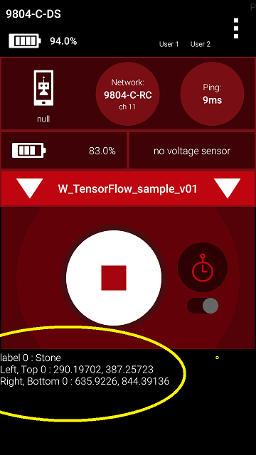
In this example, the camera is pointed at a single Stone. Its bounding box has a left edge at 290 pixels, top edge at 387 pixels, right edge at 635 pixels, and bottom edge at 844 pixels.
As the camera moves, the TFOD results will update with varying pixel coordinates, and possibly finding or losing recognitions. This process can be viewed on the RC screen or HDMI monitor, if used, but your Op Mode can react only to the data provided by the TFOD software.
Other available data includes: confidence level, width of bounding box, height of bounding box, width of overall screen image (typically 1280 pixels), height of overall screen image (typically 720 pixels), and the estimated angle to the object. The getter methods for this data can be found in the Recognitions section of the TensorFlow Object Detection menu, under Utilities.
Stones and Skystones may appear together in the camera's view. Here is an example preview on the RC phone, followed by a close-up.


The FTC software displays the Label and Confidence in very small characters at the bottom left corner of the bounding box. This information is more readily available with Telemetry as shown below. The box colors vary randomly, to distinguish one recognition from another.
A static preview is also available on the DS phone, for REV Expansion Hubs and REV Control Hubs. Here is the DS preview of the same camera view shown above on the RC phone, with its close-up.


The DS and RC previews provide the same TFOD graphics and information.
After closing the DS preview and pressing the Start button, this sample Op Mode provides Telemetry.

Here the Skystone is the first recognition (index = 0) in the List called 'recognitions'. Its bounding box X values span 314 to 626 (width of 312 pixels), and its Y values span 145 to 376 (height of 231 pixels).
The Stone is the second recognition (index = 1) in the List called 'recognitions'. Its bounding box X values span 16 to 346 (width of 330 pixels), and its Y values span 154 to 389 (height of 235 pixels).
These figures seem to agree with the preview images, with high confidence levels, and can be used by your Op Mode for analysis and robot action.
Learn and assess the characteristics of this navigation tool. You may find that certain distances, angles, and object groupings give better results. Compare this to the Skystone 2D image recognition provided by Vuforia alone, described in a separate tutorial.
You may also notice some readings are slightly erratic or ‘jumpy’, like the raw data from many advanced sensors. An FTC programming challenge is to smooth out such data to make it more useful. Ignoring rogue values, simple average, moving average, weighted average, PID control, and many other methods are available. It’s also possible to combine TFOD results with other sensor data, for a blended source of navigation input.
This is the end of reviewing the sample Op Mode. With the data provided by TFOD, your competition Op Mode can autonomously navigate on the field. The next section gives a simple example.
For illustration only, consider a simplified SKYSTONE navigation task. The robot is 24 inches from the Red Alliance perimeter wall, front camera facing the Blue Alliance side, beside the Red Skybridge and just beyond the last Stone in the undisturbed Quarry. The task: drive sideways (to the left) until a Skystone is centered in the camera image.
The sample Op Mode looped until the DS Stop button was pressed. Now the Op Mode will contain driving, and the main loop must end when the center of the Skystone bounding box reaches the center of the image.
Programming tip: Plan your programs first using plain language, also called pseudocode. This can be done with Blocks, by creating empty Functions. The name of each Function describes the action.
Programming tip: Later, each team member can work on the inner details of a Function. When ready, Functions can be combined using a laptop’s Copy and Paste functions (e.g. Control-C and Control-V).
A very simple pseudocode approach might look like this:

The central task 'Analyze Camera Image' can be expanded to several smaller tasks.
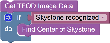
The sample Op Mode shows that 'Get TFOD Image Data' is done with one TFOD Blocks command. The old variable 'recognitions' now has a slightly more descriptive name 'allRecognitions', as suggested in the tutorial above.

The next question is whether TFOD found any recognitions, including a Skystone. If so, get some Skystone position data. Here are steps used by the sample Op Mode, except the old variable 'recognition' now has a slightly more descriptive name 'currentRecognitionData'.

The FOR loop cycles through the list of all recognitions, processing one at a time. Inside that loop, get the bounding box position only if the current item is a Skystone.

The X center position of any recognized Skystone is easily calculated as Left edge plus (Width / 2), measured in pixels.
Putting these pieces together, here is the pseudocode developed so far.

The Repeat loop should end when SkystoneCenter has reached the center of the camera's image. The robot is moving to the left, so the Skystone will enter the camera's view from the left. Its X position values will start low and increase. The X-axis center of the overall image is a constant number, simply 1/2 of the image's known width. So the beginning of the Repeat loop can look like this:

This presumes the image width was previously verified to be 1280 pixels.
The center of the Skystone box is initialized to X=0 pixels, expecting the box to enter from the left side of the camera image. This will be updated inside the loop, as soon as a Skystone is recognized. Until then, the initial value of X=0 will keep the robot driving sideways.
When completed, this pseudocode should place the robot's camera directly in front of the first Skystone found. Of course certain tasks must be done in the initialize section, before waitForStart.

And don't forget to turn off TFOD when not being used.

For safety, all Repeat loops need a second condition, "while opModeIsActive". This allows safe recovery from problems or exceptions. Also add Telemetry inside the FOR loop, similar to the sample Op Mode.
Putting all this together, here is a possible pseudocode solution.
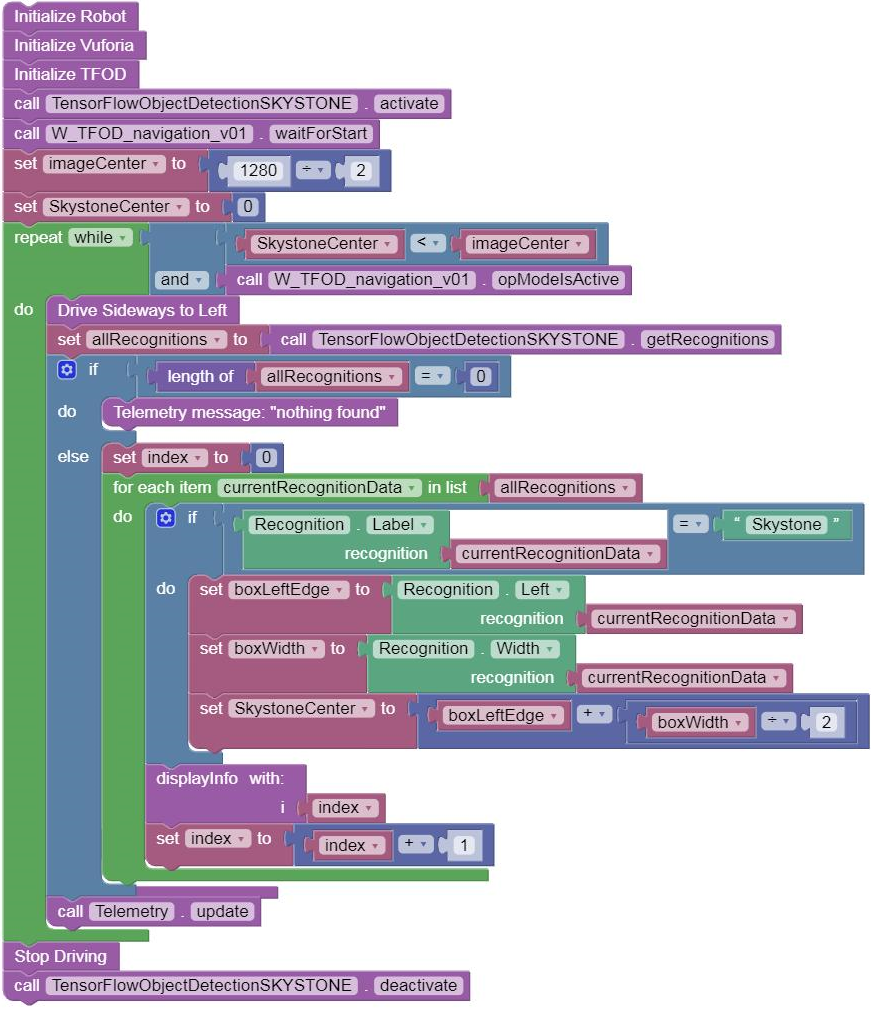
Always add many short (blue Block) and detailed (in-Block) comments, to document your work for others and yourself. This has a very high priority in the programming world.
Programming tip: action loops should also have safety time-outs. Add another loop condition, “while ElapsedTime.Time is less than your time limit”. Otherwise your robot could sit idle, or keep driving and crash.
Programming tip: optional to set a Boolean true/false variable indicating that the loop ended from a time-out, then take action accordingly.
Programming tip: Right-click on a Logic Boolean Block (AND, OR) and choose External Inputs, for a vertical arrangement of Repeat loop conditions as shown in the pseudocode above. Also available for Logic Compare Blocks (=, <, >).
This example showed how to navigate by using several pieces of information generated by TFOD, including the Label of a recognized object, and its Left edge and Width. As noted in this tutorial, many other data items are also available.
Overall, TFOD applies vision processing and machine learning to allow autonomous navigation relative to trained objects. If the field position of the recognized object is known, TFOD can also help with general navigation, not relying only on the robot's frame of reference.
Questions, comments and corrections to: [email protected]
A special Thank You! is in order for Chris Johannesen of Westside Robotics (Los Angeles) for putting together this tutorial. Thanks Chris!