Hardware explained - BelaPlatform/Bela GitHub Wiki
The Bela Wiki has moved to learn.bela.io. This material has been superseded. Click here for the maintained version.
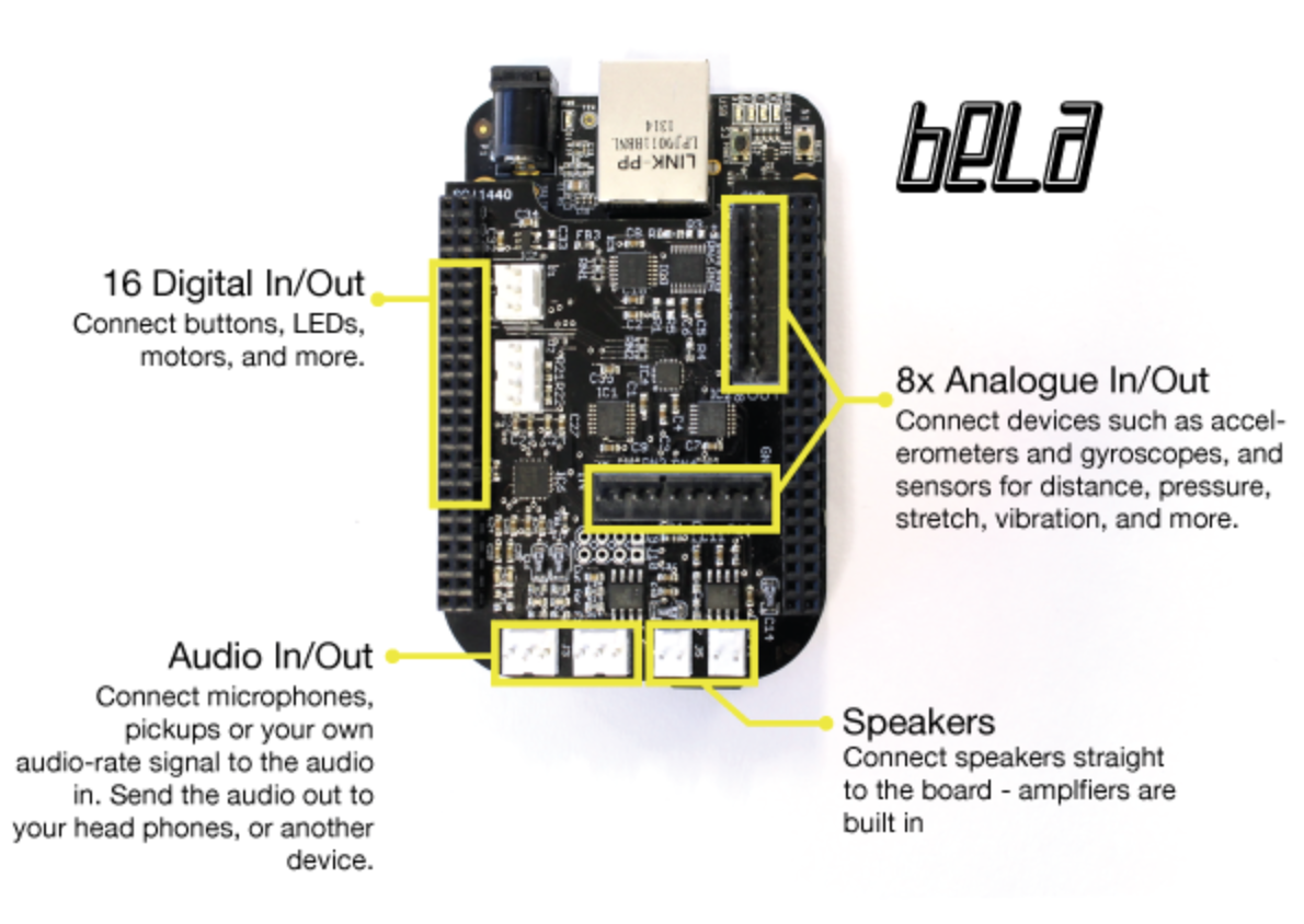
Bela's audio capabilities make it the perfect platform for creating musical instruments, modular synths or audio effect boxes. On the cape you have the following:
- Audio Input: 16-bit stereo audio input at 44.1kHz
- Audio Output: 16-bit stereo audio output at 44.1kHz
- Audio power output: 2x 1W 8ohm speaker amplifiers (available when powered from DC jack)
With the audio expander capelet it is possible to extend Bela to have six audio inputs and six audio outputs for audio heavy projects.
Bela also provides you with many ways of connecting with the physical world:
- Analog In: 8x 16-bit analog inputs at 22.05kHz
- Analog Out: 8x 16-bit analog outputs at 22.05kHz
- Digital channels: 16x digital GPIO at 44.1kHz
- Analogue I/O is also software configurable to give 4 channels at 44.1kHz or 2 channels at 88.1kHz
You can also use ethernet, USB (including MIDI), SD card storage and other features of the BeagleBone Black. See, e.g.: the loggingSensors example, the various sample-... examples, MIDI and OSC.
Voltage levels
- Digital I/O levels are 0/3.3V. Mind that these are the BeagleBone's AM3358's own digital pins, so make sure you NEVER exceed 3.3V or you will brick your BeagleBone Black. Always be careful when using 5V with the digital inputs!
The analog voltage ranges depend on the board and I/O in use. On Bela and Bela Mini:
-
Audio I/O levels depend on the adjustable settings of the audio codec. You can comfortably plug in a guitar, a dynamic microphone, a piezo pickup, most stuff really, having up to 59.5dB of gain at your disposal. You can refer to the TLV320AIC3104 datasheet for more details. The gain can be set via the Project Settings tab in the IDE.
-
Analog ins are in the range 0-4.096V (inputs are 5V tolerant).
-
Analog outs are in the range 0-5V.
On CTAG Face/Beast:
- Audio I/O are 2.5Vpp, that is 1.2dBu or -1.1dBV
The analog voltage ranges are translated into numbers in software: analog inputs are mapped to a range of 0 to 1, while audio maps to -1 to 1.
Pin diagram
See an interactive reference map of the pins and features of the cape: http://bela.io/belaDiagram/ This interactive reference map is also available in the Pin Diagram tab of the IDE.
Supply voltages
There are several places to get power supply voltages on the BeagleBone Black and Bela cape. For the pins below, refer to the interactive diagram above or to the BeagleBone header pinouts compiled by Derek Molloy.
-
3.3V is available from the BeagleBone connector P9 pins 3 and 4. This is in the corner of the BeagleBone near the 5V power socket. Always use 3.3V with digital I/O!
-
5V is available from three sources:
-
The Bela cape, on the Analog Out connector. This 5V source is in series with a 100 ohm resistor. This makes it the safest 5V source to use for experimentation and exploration, because a short circuit is unlikely to power off the board or cause damage. On the other hand, the resistor means it is not suitable for supplying more than a few milliamps of current.
-
P9 pins 7 and 8. This is the SYS_5V supply on the BeagleBone Black, which is the regulated supply coming from the USB port. It will always be available regardless of how the BeagleBone is powered, but it has a limit of 250mA of current.
-
P9 pins 5 and 6. This is the VDD_5V supply on the BeagleBone Black, which is only available when the BeagleBone Black is powered from the DC barrel connector. It is not available on the BeagleBone Green, which does not have the DC connector. Given a suitable power supply, these pins can supply up to 1A of current. These are the pins used to power the audio amplifiers on the Bela cape.
The 3.3V supply has much better noise performance than the 5V supply. Therefore, if you are using one of these supply voltages as a reference in a sensitive analog circuit, we recommend you use the 3.3V supply, or a separate low-noise voltage reference.
Unpopulated pads
On the Bela cape there are a number of unpopulated through-hole pads. An advanced user may want to solder headers or pins or components to enable the advanced features listed below. Refer to the board diagram for further details.
- 5V power supply input on J1. This can be used to power the BeagleBone and the Bela cape (the 5V pin is the same as P9_05/P9_06 and the barrel jack).
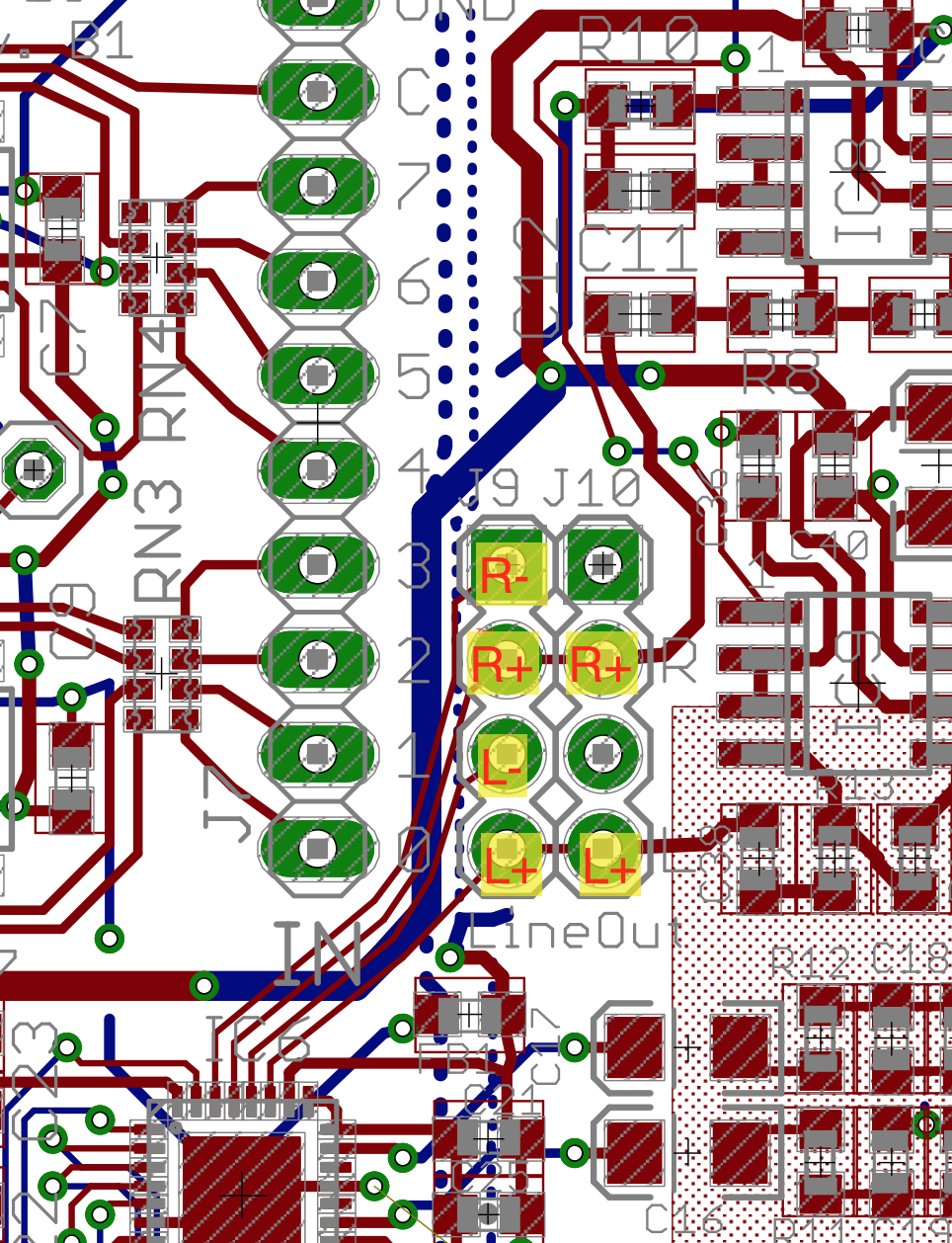
- DC-coupled, balanced line outs on J9 (with optional effect loop between audio DAC and speakers). Pinout:
- Vref. This is a high-impedance low-noise reference voltage used internally by the analog ADC. If you were to use this as a voltage reference in your circuit, you should provide a high-impedance buffer.
- MicBias (Bela cape rev B2 onwards only): this provides plug-in power from the TLV320AIC3104. The user may want to solder a 1k resistor from MicBias to one of the inputs in order to provide 2V or 2.5V (selectable via software) plug-in power to an electret capsule. See e.g.: section 11.2.1 of the datasheet.
Plug-in power
Some microphones (mostly electret-based) require "plug-in power" to work. Plug-in power is a small voltage used to power an on-board preamplifier. Normally microphones are not too strict about the exact voltage level, and common values range from 2V to 3.3V. In order to use microphones that require plug-in power on Bela, you have to connect the relevant audio input pins to an appropriate voltage source through a 1k resistor. Make sure you check the specifications of your microphones for the suitable voltage range before you follow the instructions below.
On Bela cape Rev B2 and above
The MicBias pin provides 2.5V and is the ideal voltage source for plug-in power. Depending on your use case, you may want to solder a wire, a 1x1 socket header or the resistor straight to this pin.
On any other Bela and BelaMini cape
Use the 3.3V pin (P9.03/P9.04 on Bela or P1.14/P2.23) as the voltage source.
CTAG capes
Microphones are unlikely to work properly with CTAG capes, as they only have line inputs, and do not have a microphone preamplifier. You could still use the 3.3V (P9.03/P9.04) if you wanted to give it a try. Maybe you are lucky and your microphone has a high enough output voltage.
Procedure
- Identify the appropriate voltage source for your board, as described in the preceding paragraphs.
- Identify the relevant audio input pin(s). Check your board diagram to identify the left and right input pins of the 3-pin IN connector. The Left pins is the central pin and the Right pin is the one that is closest to the OUT connector.
- On a breadboard, set up the following circuit: connect the voltage source through a 1k resistor to the audio inputs you want to provide plug-in power to. In the example diagram below, we are providing plug-in power to both audio inputs. You may decide to only connect the L or R input, depending on your needs. You may have to use socket wires to connect the audio input pins from the cape to the breadboard, and then you can use more wires to connect the breadboard to the audio connector.

- once you are happy with the breadboarded connections, you may decide to solder the resistors in place on your Bela cape. This is particularly easy on a Bela RevB2 or higher cape, as the MICBIAS pin is conveniently located in proximity of the audio input connector.
Hacks
IMPORTANT: Perform these hacks at your own risk: they void the warranty on your hardware
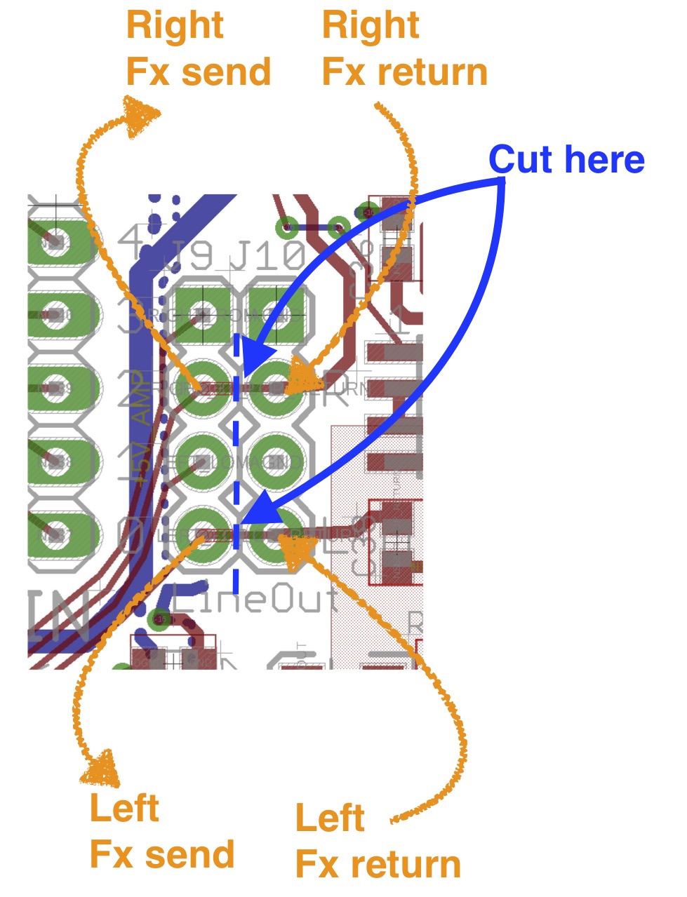
Drive the speaker amps through an effect loop or using an external signal
The "hot" signal of the line-level output of the Bela cape is connected to the input of the speaker amplifier through unpopulated pads J9/J10 (see above). By cutting the signal traces that go from J9 to J10, you can insert an external effect loop between the Bela codec's audio out and the input of the speaker amplifier. You can even decide to simply use the "Fx return" signal to inject an arbitrary external signal into the speaker amps, for instance if you want to send to the speaker the signal from two of the channels of a CTAG board.
Cut along the dashed line in the picture below, and insert the effect loop where indicated. If one day you want to undo your mod, simply join back together the pads adjacent to the traces you cut. Please refer to the full circuit diagram and schematic for your board revision.