Example projects and tutorials - BelaPlatform/Bela GitHub Wiki
The Bela Wiki has moved to learn.bela.io. This material has been superseded. Click here for the maintained version.
Example projects and tutorials
You can access the example projects through the Example Projects tab of the Bela IDE. Each example also has an accompanying example document that leads you through the example step-by-step. You can get to this document by clicking on the example doc button in the top righthand corner of the text editor.
Below is a list of the sample sketches, and what they do.
Basics:
Digital:
Analog:
Sensors:
Audio:
PureData:
Instruments:
minimal
This sketch introduces the structure of a Bela project.
The structure of a Bela project
A collection of Bela files are called a "project".
If you open a project folder in the above repository, you'll see that each of these Bela project contains at least one file, render.cpp (some projects have additional files, but every project has at least this). The main.cpp is the second most common file to see in a project but you don't really have to worry about; it contains helper functions and things that run command line arguments. Most work is done in the render.cpp file.
The structure of a render.cpp file
A render.cpp file has three functions: setup(), render() and cleanup().
setup() is an initialisation function which runs before audio rendering begins.
It is called once when the project starts. Use it to prepare any memory or
resources that will be needed in render().
render() is a function that is regularly called, over and over continuously, at
the highest priority by the audio engine. It is used to process audio and
sensor data. This function is called regularly by the system every time there
is a new block of audio and/or sensor data to process.
cleanup() is a function that is called when the program stops, to finish up any
processes that might still be running.
Here we will briefly explain each function and the structure of the render.cpp
Before any of the functions
At the top of the file, include any libraries you might need.
Additionally, declare any global variables. In these tutorial sketches, all
global variables are preceded by a g so we always know which variables are
global - gSampleData, for example. It's not mandatory but is a really good way
of keeping track of what's global and what's not.
Sometimes it's necessary to access a variable from another file, such as
main.cpp. In this case, precede this variable with the keyword extern.
Function arguments
setup(), render() and cleanup() each take the same arguments. These are:
BelaContext *context
void *userData
These arguments are pointers to data structures. The main one that's used is
context, which is a pointer to a data structure containing lots of information
you need.
Take a look at what's in the data structure in the API reference tab.
You can access any of these bits of information about current audio and sensor
settings and pointers to data buffers that are contained in the data structure
like this: context->name_of_item.
For example, context->audioInChannels returns the number of audio input channels.
context->audioSampleRate returns the audio sample rate.
context->audioIn[n] would give you the current input sample (assuming that
your input is mono - if it's not you will have to account for multiple channels).
Note that audioIn, audioOut, analogIn, analogOut are all arrays (buffers).
passthrough
Audio and analog passthrough: input to output
This sketch demonstrates how to read from and write to the audio and analog input and output buffers.
In render() you'll see a nested for loop structure. You'll see this in all Bela projects.
The first for loop cycles through audioFrames, the second through
audioInChannels (in this case left 0 and right 1).
You can access any information about current audio and sensor settings like this:
context->name_of_item. For example context->audioInChannels returns current number of input channels,
context->audioFrames returns the current number of audio frames,
context->audioSampleRate returns the audio sample rate.
You can look at all the information you can access in ::BelaContext.
Reading and writing from the audio buffers
The simplest way to read samples from the audio input buffer is with
audioRead() which we pass three arguments: context, current audio
frame and current channel. In this example we have
audioRead(context, n, ch) where both n and ch are provided by
the nested for loop structure.
We can write samples to the audio output buffer in a similar way using
audioWrite(). This has a fourth argument which is the value of to output.
For example audioWrite(context, n, ch, value_to_output).
Reading and writing from the analog buffers
The same is true for analogRead() and analogWrite().
Note that for the analog channels we write to and read from the buffers in a separate set
of nested for loops. This is because the they are sampled at half audio rate by default.
The first of these for loops cycles through analogFrames, the second through
analogInChannels.
By setting audioWriteFrame(context, n, ch, audioReadFrame(context, n, ch)) and
analogWrite(context, n, ch, analogReadFrame(context, n, ch)) we have a simple
passthrough of audio input to output and analog input to output.
It is also possible to address the buffers directly, for example:
context->audioOut[n * context->audioOutChannels + ch].
sinetone
Producing your first bleep!
This sketch is the hello world of embedded interactive audio. Better known as bleep, it produces a sine tone.
The frequency of the sine tone is determined by a global variable, gFrequency.
The sine tone is produced by incrementing the phase of a sin function
on every audio frame.
In render() you'll see a nested for loop structure. You'll see this in all Bela projects. The first for loop cycles through 'audioFrames', the second through 'audioChannels' (in this case left 0 and right 1). It is good to familiarise yourself with this structure as it's fundamental to producing sound with the system.
scope
Oscilloscope in-browser
This sketch demonstrates the scope feature of the IDE.
The scope is instantiated at the top of the file via Scope scope;
In setup() we define how many channels the scope should have and the sample
rate that it should run at via scope.setup(3, context->audioSampleRate).
In render() we choose what the scope log via scope.log(out, out2, out3).
In this example the scope is logging three sine waves with different phases. To see
the output click on the Open Scope button.
An additional option is to set the trigger of the oscilloscope from within render().
In this example we are triggering the scope when oscillator 1 becomes less than
oscillator 2 via scope.trigger(). Note that this functionality only takes effect
when the triggering mode is set to custom in the scope UI.
Printing to the console
This example demonstrates how to print to the console. When working within the audio thread
use the function rt_printf(). This has the same functionality as printf() but is safe to call
from the audio thread. However, make sure to not make too many calls to this function within a
render loop as this may overload the CPU and/or stall communication with the board.
In the render() function above a counter is implemented in order to only print to the console
after a specified interval has passed. A counter variable is used to keep track of the amount
of samples elapsed after starting the program.
The usage of rt_printf() is identical to printf(): http://en.cppreference.com/w/cpp/io/c/fprintf
Similarly, Xenomai functions exist to replace fprintf(), vfprintf(), rt_vprintf(). See
here for more on the rtdk real-time printing library here.
digital-output
Blinking an LED
This sketch shows the simplest case of digital out.
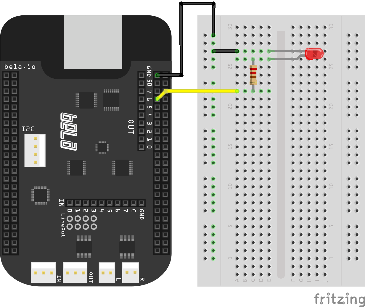
- Connect an LED in series with a 470ohm resistor between P8_07 and ground.
The led is blinked on and off by setting the digital pin HIGH and LOW every interval seconds which is set in
render().
In setup() the pin mode must be set to output mode via pinMode(). For example:
pinMode(context, 0, P8_07, OUTPUT).
In render() the output of the digital pins is set by digitalWrite(). For example:
digitalWrite(context, n, P8_07, status) where status can be equal to
either HIGH or LOW. When set HIGH the pin will give 3.3V, when set to
LOW 0V.
Note that there are two ways of specifying the digital pin: using the GPIO label (e.g. P8_07), or using the digital IO index (e.g. 0)
To keep track of elapsed time we have a sample counter count. When the count reaches
a certain limit it switches state to either HIGH or LOW depending on its current
value. In this case the limit is context->digitalSampleRate*interval which
allows us to write the desired interval in seconds, stored in interval.
digital-input
Switching an LED on and off
This example brings together digital input and digital output. The program will read a button and turn the LED on and off according to the state of the button.
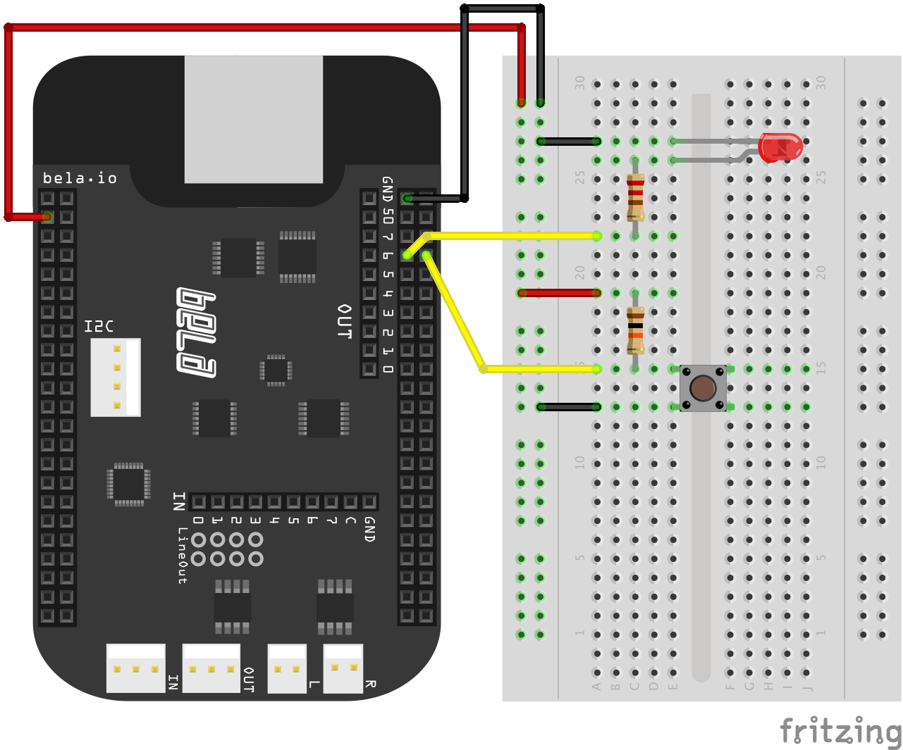
- connect an LED in series with a 470ohm resistor between P8_07 and ground.
- connect a 1k resistor to P9_03 (+3.3V),
- connect the other end of the resistor to both a button and P8_08
- connect the other end of the button to ground.
Before using the digital pins we need to set whether they are input or output.
This is done via pinMode(context, 0, P8_08, INPUT);.
You will notice that the LED will normally stay off and will turn on as long as
the button is pressed. This is due to the fact that the LED is set to the same
value read at input P8_08. When the button is not pressed, P8_08 is LOW and so
P8_07 is set to LOW as well, so that the LED conducts and emits light. When
the button is pressed, P8_08 goes HIGH and P8_07 is set to HIGH, turning off the LED.
Note that there are two ways of specifying the digital pin: using the GPIO label (e.g. P8_07),
or using the digital IO index (e.g. 0)
As an exercise try and change the code so that the LED only turns off when the button is pressed.
level-meter
Visualise music with leds
This example shows how to make an audio level meter with a set of ten LEDs.
- Connect an LED in series with a 470ohm resistor between every Digital pin 0 - 9 and ground.
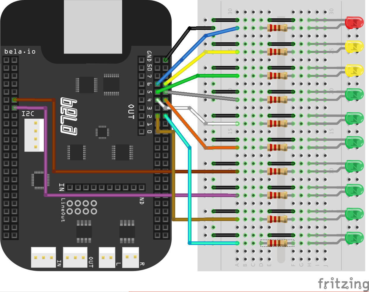
You will also need to connect an audio adapter to the audio input pins and connect something that can produce an audio signal to this (a laptop, mp3 player, phone or keyboard). The code preforms peak detection on the audio input and lights the LEDs once the amplitude of the input signal passes a certain threshold stored in gThresholds[i]. Each LED has its own threshold, the values of which are set in setup() and are steps of -3dB. All digital pins are set to output pinMode(context, 0, i, OUTPUT); and they are toggled on and off in render() when the amplitude passes the threshold for that LED. The LEDs below the current peak value always remain lit to create a classic amplitude peak meter. The audio input is passed through to the output so you can listen as you watch the light show.
analog-input
Connecting potentiometers
This sketch produces a sine tone, the frequency and amplitude of which are
modulated by data received on the analog input pins. Before looping through each audio
frame, we declare a value for the frequency and amplitude of our sine tone;
we adjust these values by taking in data from analog sensors (for example potentiometers)
with analogRead().
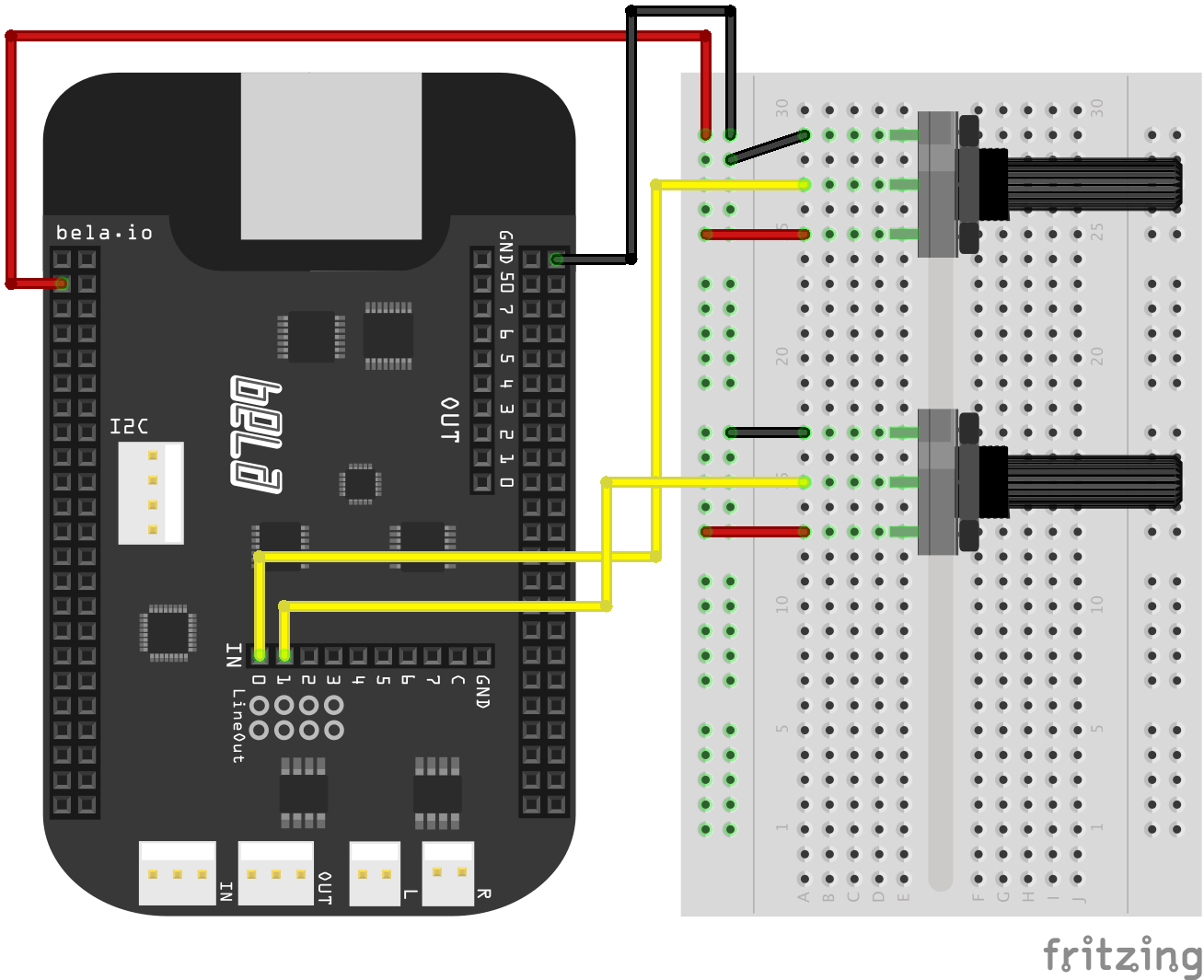
- connect a 10K pot to 3.3V and GND on its 1st and 3rd pins.
- connect the 2nd middle pin of the pot to analogIn 0.
- connect another 10K pot in the same way but with the middle pin connected to analogIn 1.
The important thing to notice is that audio is sampled twice as often as analog data. The audio sampling rate is 44.1kHz (44100 frames per second) and the analog sampling rate is 22.05kHz (22050 frames per second). Notice that we are processing the analog data and updating frequency and amplitude only on every second audio sample, since the analog sampling rate is half that of the audio.
if(!(n % gAudioFramesPerAnalogFrame)) {
    // Even audio samples: update frequency and amplitude from the matrix
    frequency = map(analogRead(context, n/gAudioFramesPerAnalogFrame, gSensorInputFrequency), 0, 1, 100, 1000);
    amplitude = analogRead(context, n/gAudioFramesPerAnalogFrame, gSensorInputAmplitude);
}
analog-output
Fading LEDs
This sketch uses a sine wave to drive the brightness of a series of LEDs
connected to the eight analog out pins. Again you can see the nested for loop
structure but this time for the analog output channels rather than the audio.
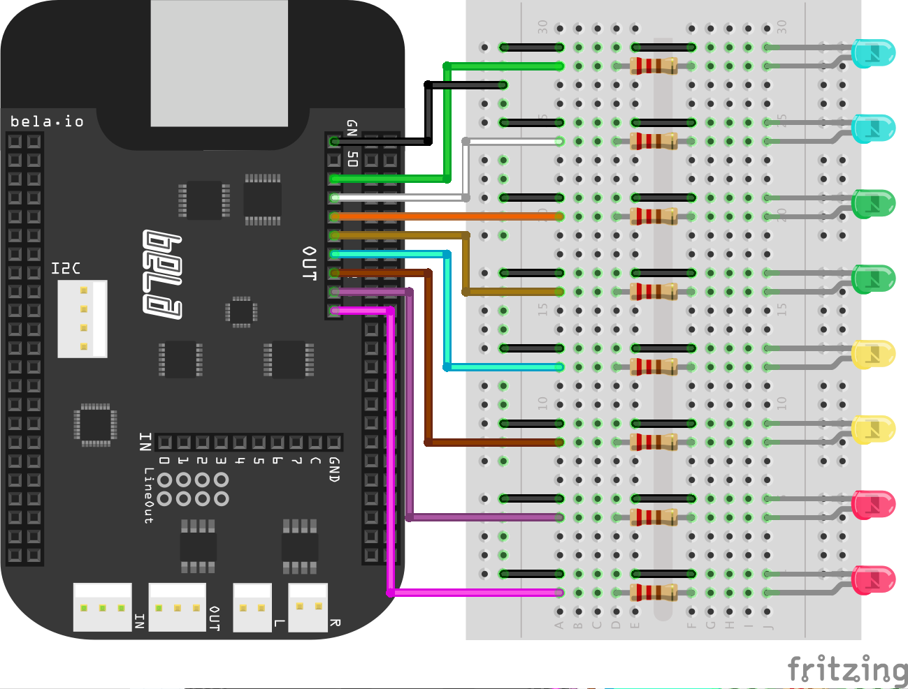
- connect an LED in series with a 470ohm resistor between each of the analogOut pins and ground.
Within the first for loop in render we cycle through each frame in the analog output matrix. At each frame we then cycle through the analog output channels with another for loop and set the output voltage according to the phase of a sine tone that acts as an LFO. The analog output pins can provide a voltage of ~4.092V.
The output on each pin is set with analogWrite() within the for loop that
cycles through the analog output channels. This needs to be provided with
arguments as follows analogWrite(context, n, channel, out). Channel is
where the you give the address of the analog output pin (in this case we cycle
through each pin address in the for loop), out is the variable that holds the
desired output (in this case set by the sine wave) and n is the frame number
(given by the other for loop).
Notice that the phase of the brightness cycle for each led is different. This is achieved by updating a variable that stores a relative phase value. This variable is advanced by pi/4 (1/8 of a full rotation) for each channel giving each of the eight LEDs a different phase.
scope-analog
Scoping sensor input
This example reads from analogue inputs 0 and 1 via analogRead() and
generates a sine wave with amplitude and frequency determined by their values.
It's best to connect a 10K potentiometer to each of these analog inputs. Far
left and far right pins of the pot go to 3.3V and GND, the middle should be
connected to the analog in pins.
The sine wave is then plotted on the oscilloscope. Click the Open Scope button to view the results. As you turn the potentiometers you will see the amplitude and frequency of the sine wave change. You can also see the two sensor readings plotted on the oscilloscope.
The scope is initialised in setup() where the number of channels and sampling rate
are set.
scope.setup(3, context->audioSampleRate);
We can then pass signals to the scope in render() using:
scope.log(out, gIn1, gIn2);
This project also shows as example of map() which allows you to re-scale a number
from one range to another. Note that map() does not constrain your variable
within the upper and lower limits. If you want to do this use the constrain()
function.
LDR
Using light as a controller
This example demonstrates how to hook up a Light Dependent Resistor
(LDR), also know as a photo-resistor, and use it to control the
volume of white noise. If you run this project straight away
after connecting up the LDR you will notice that the LDR reacts
to changes in the light condition but in a pretty unsatisfying way.
This is because we need to set the thresholds of the map() function
based on the ambient light condition.
To begin let's connect the LDR.
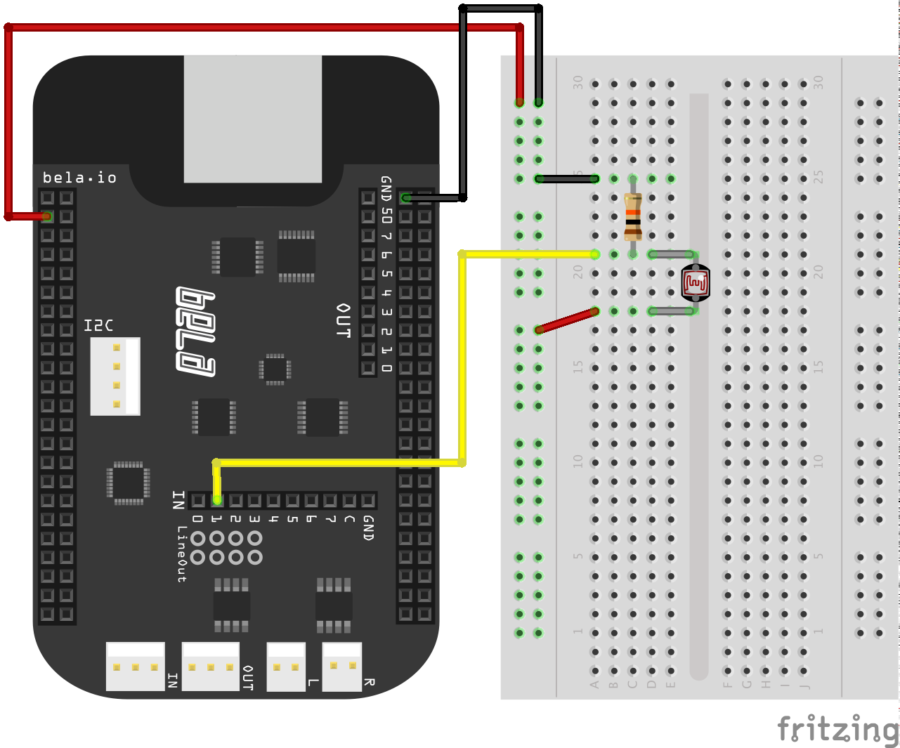
- connect one leg of the LDR to 3.3V
- connect the other leg of the LDR to analog input 1
- connect one leg of a 10KOhm resistor to this leg of the LDR as well
- connect the other leg of the resistor to ground
The resistance of the LDR changes depending on the amount of light it receives (more light -> less resistance). To measure this change in resistance we need a fixed value resistor (10kOhms in this example) to compare the reading with. This is know as a voltage divider circuit. The 3.3V will be shared between the two resistors: how much of a share of voltage each of the resistors take is proportional to their resistances. As the resistance of the LDR changes the amount of voltage on each resistor changes and we can measure this change to tell how much light the LDR is receiving.
In order to use the LDR as a volume control we need to set the thresholds
for ambient light and for when it has a bright light shone close to it.
To do this comment out this section of code in render():
if(!n%2){
    if(gSampleCount >= 44100) {
        rt_printf("%f\n", analogRead(context, n, 1));
        gSampleCount = 0;
    }
}
gSampleCount++;
This prints the value of the LDR reading to the console once a second.
Now you can set the variables gDark and gLight with the reading
of ambient light in the room and with the reading when a torch is
shone directly at the LDR. Update the variables, re-comment out the code and
run the example. Now you should be able to bring the white noise from
silence to full volume depending on the amount light.
Note that when you cover the LDR you should also hear an increase in
volume of the white noise. This is because the map() function is not
constrained which means that it outputs negative number when it gets
darker than the threshold set in gDark. To stop this behaviour you
can use the constrain() function to force the LDR readings to remain
within a certain range (for example gDark to gLight).
capacitive-touch
Capacitive touch sensing with MPR121
This sketch allows you to hook up an MPR121 capactive touch sensing device to Bela, for example the SparkFun Capacitive Touch Sensor Breakout - MPR121. The breakout board gives you 12 electrode connections.
To get this working with Bela you need to connect the breakout board to the I2C terminal on the Bela board. See the Pin guide for details of which pin is which.
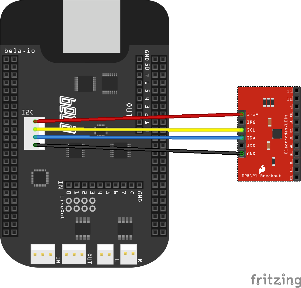
The sensor data will then be available for you to use in the array
sensorValue[NUM_TOUCH_PINS].
accelerometer
Accelerometer
How to connect an accelerometer:
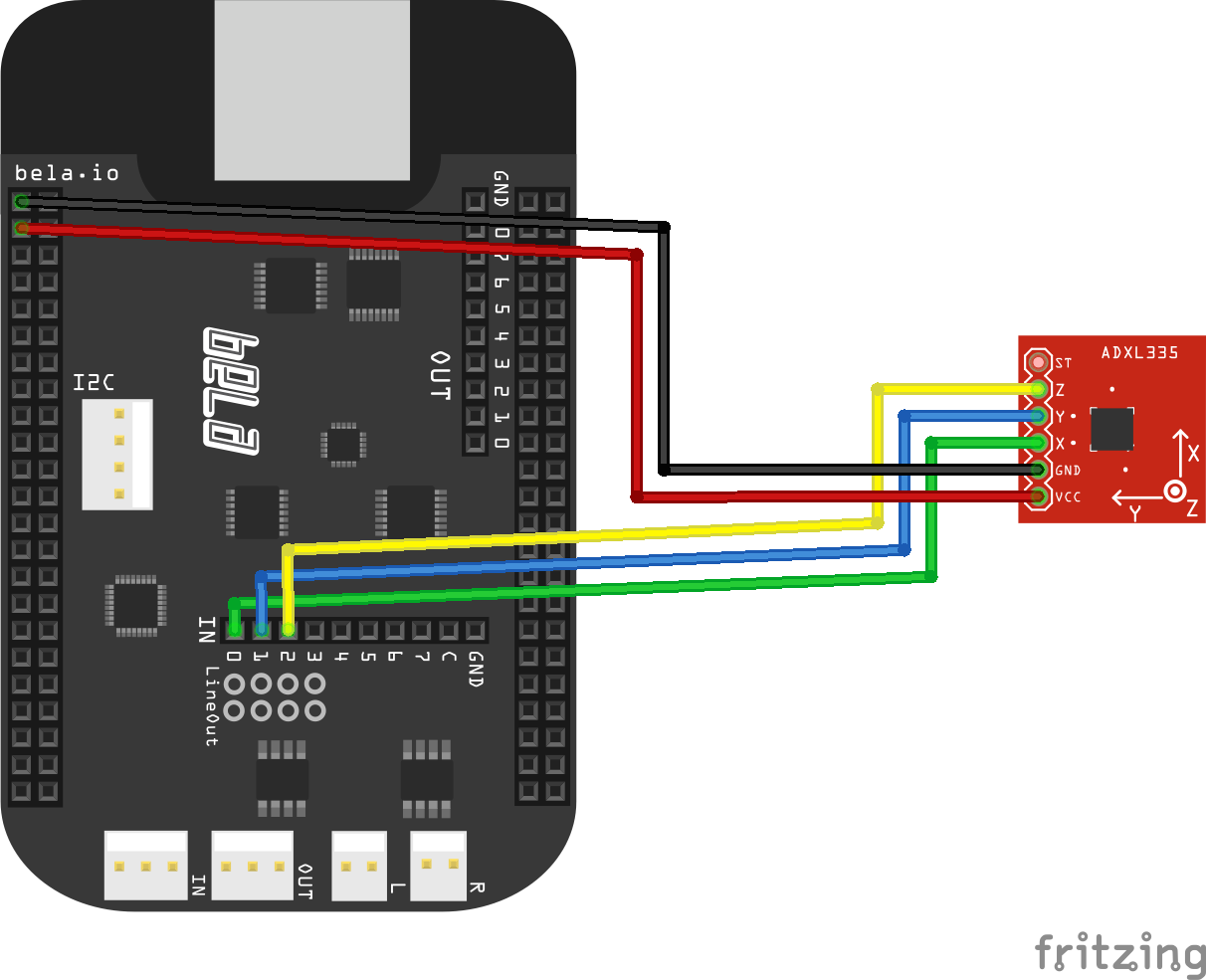
This is required for some of the PureData examples.
sample-piezo
Piezo strike to WAV file playback
This sketch shows how to playback audio samples from a buffer using onset detection of strikes detected by a piezo sensor.
An audio file is loaded into a buffer SampleData as gSampleData. This is
accessed with a read pointer that is incremented at audio rate within the render
function: out += gSampleData.samples[gReadPtr++].
Note that the read pointer is stopped from incrementing past the length of the
gSampleData. This is achieved by comparing the read pointer value against the
sample length which we can access as follows: gSampleData.sampleLen.
The piezo is connected to Bela through a simple voltage divider circuit.
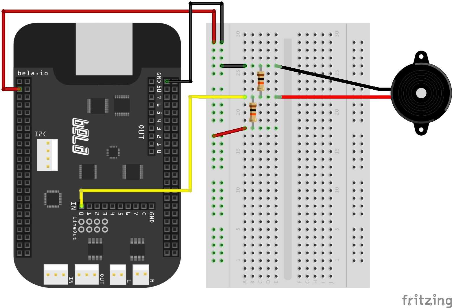
- Connect a 1.8 MOhm resistor between the positive (red) and negative (black) leads of the piezo
- Also connect the negative side to ground
- Connect analog input 0 to the positive side
- Connect another 1.8 MOhm resistor between positive and 3.3V
In order to get a coherent trigger from the piezo disk we have to go through a few stages of signal taming. The first is a DC offset filter which recentres the signal around 0. This is necessary as our voltage divider circuit pushes the piezo input signal to half the input voltage range, allowing us to read the piezo's full output.
As a piezo disk behaves like a microphone it outputs both negative and positive values. A second step we have to take before detecting strikes is to fullwave rectify the signal, this gives us only positive values.
Next we perform the onset detection. We do this by looking for a downwards trend in the sensor data
after a rise. Once we've identified this we can say that a peak has occured and trigger the sample
to play. We do this by setting gReadPtr = 0;.
This type of onset detection is by no means perfect. Really we should lowpass filter the piezo signal before performing the onset detection algorithm and implement some kind of debounce on the stikes to avoid multiple strikes being detected for a single strike.
delay
Delay, delay, delay, delay...
This example demonstrates how to apply a feedback delay with an incorporated low-pass filter to an audio signal.
In order to create a delay effect we need to allocate a buffer (i.e. an array of samples) that holds previous samples.
Every time we output a sample we need to go back in time and retrieve the sample that occurred n samples ago, where
n is our delay in samples. The buffer allows us to do just this. For every incoming sample we write its value into
the buffer. We use a so-called write pointer (gDelayBufWritePtr) in order to keep track of the index of the buffer
we need to write into. This write pointer is incremented on every sample and wrapped back around to 0 when its reached
the last index of the buffer size (this technique is commonly referred to as a circular buffer or a ring buffer).
We go a bit further by applying feedback and filtering to the delay in order to make the effect more interesting. To
apply feedback to the delay, we take the sample that occurred gDelayInSamples ago, multiply it by our
gDelayFeedbackAmount parameter and add it to the dry input signal that we will write into the buffer. This way, there
will always be a trace of the previously delayed sample in the output that will slowly fade away over time.
Next, we apply a low-pass filter. We have pre-calculated the coefficients that are required to apply a Butterworth
(or biquad) filter, which is expressed as follows: y = a0x0 + a1x1 + a2x2 + a3y1 + a4*y2, where x0 and x1 are
the previous input (i.e. unfiltered) samples and y0 and y1 are the previous output (i.e. filtered) samples.
We keep track of these previous input and output samples for each channel using global variables in order to apply
the filter.
Finally we take the processed sample for each channel and write it into the corresponding delay buffer (gDelayBuffer_l
and gDelayBuffer_r), so that in the future (after gDelayInSamples samples) we can retrieve it again! Last but not
least, we read the sample from the buffer that was written gDelayInSamples ago and add it to the output.
Note that we have to ways of changing the volume of the delay effect. One way is to change the overall gain using
the gDelayAmount parameter: this will immediately raise or lower the volume of the delayed signal. The other option
is to use the gDelayAmountPre parameter, which will apply gain to the input of the delay line. The advantage of
using this parameter is that when turning down the gain we can let the delay ring out while not letting any new
input into the effect. Conversely, we can introduce the delay effect naturally without fading in previous output
of the effect.
tremolo
A simple tremolo effect
This sketch demonstrates how to make a simple tremolo effect with one potiometer to control the rate of the effect. A tremolo effect is a simple type of amplitude modulation where the amplitude of one signal is continuous modulated by the amplitude of another. This is achieved by multiplying two signals together.
In this example we want to create a tremolo effect like that you would find in a guitar effects box so our first signal will be our audio input into which we could plug a guitar or external sound source. This will be our 'carrier' signal.
The second signal that we will use, the 'modulator', will be a low freqeuncy oscillator (LFO),
in this case a sinetone which we will generate in the same way as the 01-Basic/sinetone example.
The frequency of this sinetone is determined by a global variable, gFrequency. Again, the
sinetone is produced by incrementing the phase of a sine function on every audio frame.
In render() you'll see two nested for loop structures, one for audio and the other for the
analogs. You should be pretty familiar with this structure by now. In the first of these loops
we deal with all the audio -- in the second with reading the analog input channels. We read the
value of analog input 0 and map it to an appropriate range for controlling the frequency
of the sine tone.
The lfo is then mulitplied together with the audio input and sent to the audio output.
Hardware
- connect a 10K pot to 3.3V and GND on its 1st and 3rd pins.
- connect the 2nd middle pin of the pot to analogIn 0.
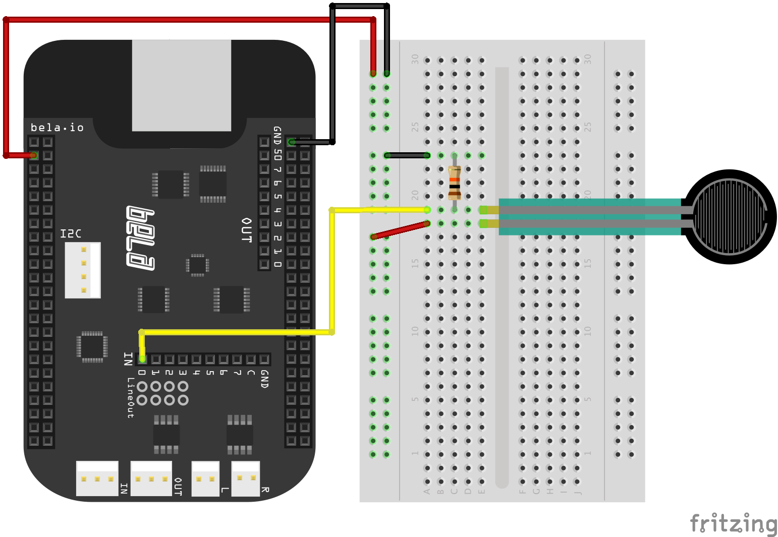
rubberDuckie
Using an FSR to control a rubber duck sound model with PureData.
For this example we use a Force Sensing Resistor (FSR) to control a physical model of a squeezable rubber duck.
- connect one leg of the FSR to 3.3V
- connect the other leg of the FSR to analog input 0
- also connect this leg to a 10KOhm resistor that goes to ground
This is another example of a voltage divider circuit - as you press the FSR its resistance decreases -- we measure the change in voltage at the analog input. In the PureData patch we then calculate the differential of this input signal (how much it changes) and use this to drive the sound model. This gives the sound model a much more realistic response when the FSR is squeezed. Try removing the differential and listen to how it sounds. Open up the patch in the IDE to find out more details about the sound model.
airharp
This project is a instrument that uses an accelerometer to sense movement. The movement of the accelerometer is used to excite a physical model of 9 strings.
- Connect the X, Y and Z of the accelerometer to analog inputs 0, 1 and 2 respectively.
- Connect the GND of the accelerometer to ground and VCC to 5V
As you tilt the accelerometer along one axis it will move a virtual mass across the strings, plucking each string as it passes. As well as tilting it you can try violently shaking it back and forth which will create a strumming effect like on a guitar. This shows the great variety of gestures that you can get from a simple accelerometer and also shows some techniques for using this sensor to control sound synthesis. Note that the panning of the strings changes as you move the sensor, high strings are in one ear and low strings in the other. Try attaching the accelerometer to a ruler or piece of wood and note how the interaction with the instrument changes depending on the position of the sensor.