Sensors - xxyypp/IBM_Dementia GitHub Wiki
Introduction
The device needs to be able to detect when the user needs help without requiring an active participation. Sensors are therefore needed, and by using the sensor data, Paige tries to determine how the user is feeling. Patient temperature, humidity (related to sweat) and heart rate were determined to be the most basic and easy to use health signals. Paige is therefore equipped with an Adafruit BME280 Temperature and humidity sensor and a Pulse sensor.
Design choices:
These sensors are soldered onto a board, fixed under the Raspberry Pi’s that is directly connected to the computer’s GPIO pins. Their positioning allows them to be as close as possible to the patient’s skin.
For optimal operating conditions, the BME280 needs to face the skin, yet the board connecting the GPIO pins to the soldering board faces up. The decision to split the board in two and reverse one half was therefore taken. The pulse sensor and its Analog to Digital converter are both on the same board as the GPIO connection whereas the temperature sensor is on the reversed board.
To save space on the soldering board, only one column of the GPIO connector was soldered onto the the board since all the pins used by the Prototype lie on the odd numbered pin side.
Setting-Up the Pulse Sensor
Before placing the sensors onto the board, it is necessary to make sure that they function in the desired way and log the data in the required format. Firstly, the Pulse sensor Amped works through I2C, so it is necessary to configure I2C setting on the Raspberry Pi as shown under the following link https://learn.adafruit.com/adafruits-raspberry-pi-lesson-4-gpio-setup/configuring-i2c. After the I2C communication is configured on the Raspberry Pi, it is a matter of running an open-source Python script available under https://github.com/udayankumar/heart-rate-raspberry-pi/blob/master/heartBeats.py. This will enable the sensor to communicate with the Raspberry Pi and read heart rate in beats per minute.
The BME280 sensor is connected in a very similar way as the Pulse Sensor Amped. Once again, an I2C connection must be set-up with the Raspberry Pi, just like with the pulse sensor and then both sensors can be connected in parallel for simultaneous I2C communication. The code needed to read temperature and humidity is used from a code sample for the BME680 sensor under https://github.com/pimoroni/bme680/tree/master/examples with alterations to fit the specific function for the BME280. Namely, the initialisation parameters have to be adjusted to fit the BME280. After these set-up instructions, both chips can be connected and used in parallel I2C communication to the Raspberry Pi.
The two scripts were combined into a custom script that you will have to Download onto the Raspberry Pi's Desktop:
Assembling the board:
The board has four major components, the row connection to the GPIO pins (Pin 1-39, only odds), the ADS1115 Analog to Digital converter (ADC), the pulse sensor connections and the BME280 temperature and Humidity sensor.
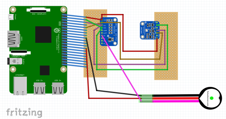
As illustrated in the schematic, the ADC directly connects to the GPIO row with the following connections:
- VDD to Pin 1
- Ground to Pin 9
- SCL to Pin 5
- SDA to Pin 3
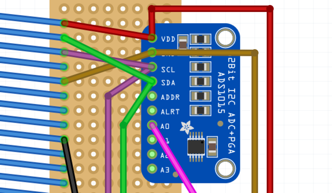
The pulse sensor connects to both the GPIO row and the ADC:
- Vcc to Pin 17
- Ground to Pin 25
- Signal to A0 of the ADC
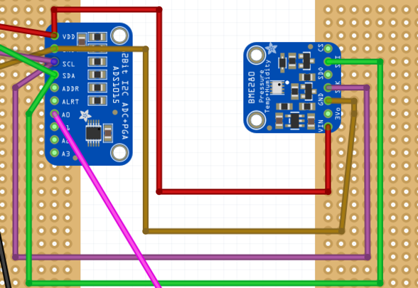
The BME280 communicates to the GPIO pins through the ADC:
- Vin to VDD of the ADC
- Ground to Ground of the ADC
- SCK to SCL of the ADC
- SDI to SDA of the ADC
Once everything is connected properly, both sides can be fixed to the bottom of the Raspberry Pi, with the BME280 reversed as such:
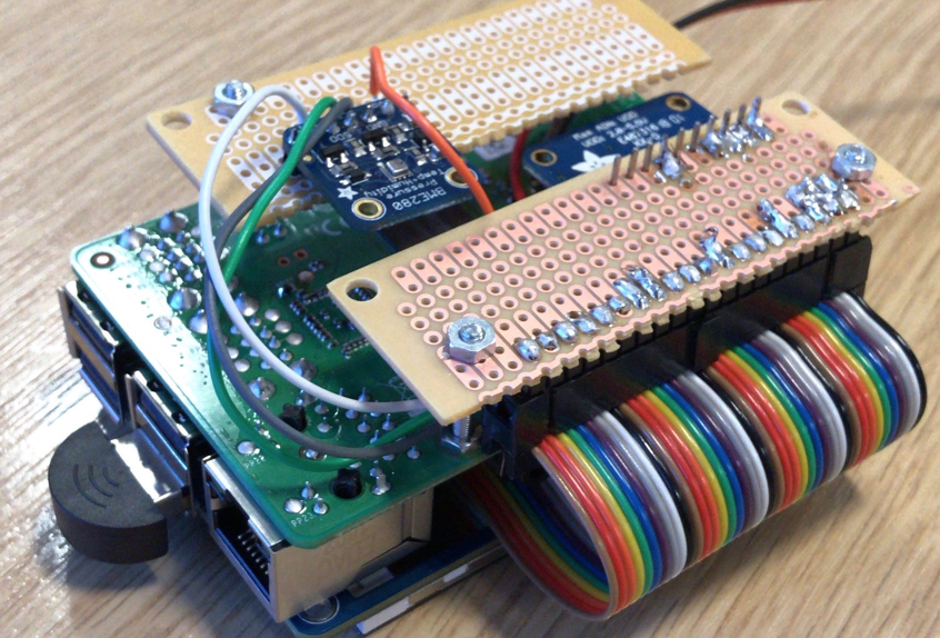
Using both the display and the GPIO Pins:
The sensor board doesn’t directly connect to the Raspberry Pi’s GPIO Pins since these are all used to connect the PiTFT screen. The ribbon cable that goes to the sensor board comes from the bottom of the PiTFT on a relayed GPIO connection.