Up and running with Seeed Sensor Kit and Intel Edison - w4ilun/edison-guides GitHub Wiki

STOP: BEFORE DOING ANTHING FLASH YOUR EDISON IF YOU HAVE NOT DONE SO ALREADY.
This guide will walk you through how to get up and running with Intel® Edison + Arduino and the Seeed Studio Grove Starter Kit Plus. Click here guidance on flashing your Edison (if it is new) to ensure it has the latest software on it.
Required Components
- Seeed Studios Grove Starter Kit Plus
- Intel® Edison + Arduino Breakout Kit
- 1 Micro-USB ( 1 comes in the Seeed Studio Kit) cable
Setting Up
- Download Edison Arduino IDE
- Download the Seeed Studios Sketchbook Starter
- Optional: Install Bloop on your Mac, a CLI tool which automates many common Intel Edison tasks
Install the Sketchbook
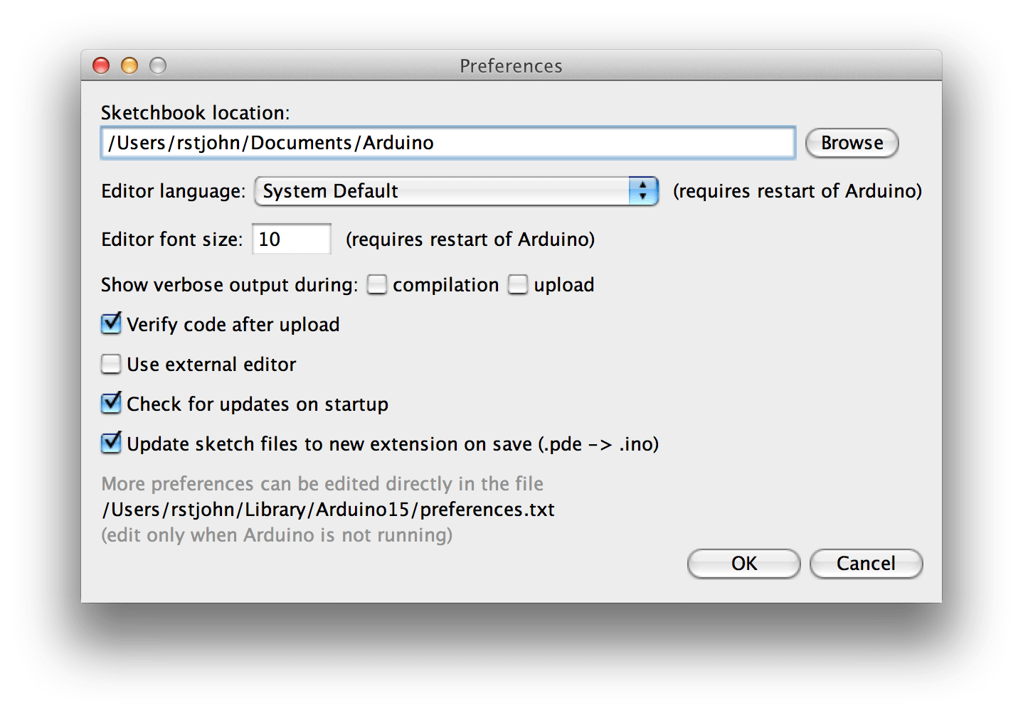
- Open the Arduino IDE for Edison after installing it
- Click “Preferences” to discover the location of the Sketchbook
- Click “Browse”
- Unzip and copy the above Sketchbook folder into the directory and rename it “SeeedStudios”
Plugging in Edison

If you have not already, remove the Intel Edison + Arduino breakout board and snap the Edison into the board following Intel’s documentation. Make sure to screw the Edison into position and attach the plastic legs using the provided bits.

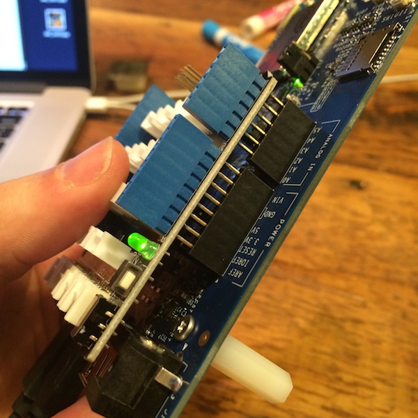
Powering Edison

On the Arduino Breakout Board, plug one Micro-USB cable into your computer and the other end into the Inside or Middle Micro-USB jack. A green light should come on indicating the board is powered. Note: If you want to also be able to “screen” into your Edison, you will also need to plug in a second Micro-USB cable into the outside jack. One is enough for simply using Edison with Arduino IDE.
Pro-Tip: Give Edison a few seconds (perhaps 30-60) to boot up. The ports may not appear in the Arduino IDE drop down until Edison has had a chance to get started.
Lets Add The Base Shield

Look underneath the LED screen and pull up the pink styrofoam in your Seeed Studio kit to locate the Base Shield unit.

The Base Shield offers a variety of plugs for connecting your various sensors to your Intel Edison.
Next, attach the Base Shield to your Arduino Breakout Board and press down firmly. A green light will turn on when the unit is powered.
Plugging In The Temperature Sensor

Locate the temperature sensor, it will say “Temperature Sensor” on the back side.

Next, use one of the provided wires (located under the white plastic shell) to attach it to your Base Shield unit. Make sure to plug the wire into the port marked “A0.”
Note: A0 is the default port in the temperature sketch we will use but you could change it as desired.
Applying The Temperature Sketch

If you haven’t looked through the booklet yet, it contains a variety of instructions on basic sketches. According to the “Grove – Temperature Sensor” – we need to click “File -> Sketchbook -> SeedStudio -> Grove_Temperature_Sensor” to load the basic temperature sketch.

Now click click the “Upload” button on the sketch which is displayed.

You should see a message “Transfer Complete” if it was successful, otherwise, check my error troubleshoot over here.
Viewing temperature sensor results
To view the temperature reading, click the “Serial Monitor” button in the upper right hand corner of the Arduino IDE. See below:
If it worked, you should see the following output:
