Filtering - ucdavis/erplab GitHub Wiki
Filtering
Filtering is a complex and often poorly understood and incorrectly used aspect of EEG and ERP processing, and ERPLAB is designed to make it easy for users to filter their data properly. Filtering is done slightly differently depending on whether you are filtering continuous EEG, epoched EEG, or averaged ERPs. The filtering GUI looks nearly the same for all three types of filtering, however.
ERPLAB provides three classes of filters: 1) Infinite impulse response (IIR) Butterworth filters; 2) Finite impulse response (FIR) filters; and 3) Parks-McClellan notch filters. The FIR filters are rather limited at present, and we will increase the number of FIR options in the future (e.g., including Gaussian impulse response functions). At present, we recommend using the Butterworth filters for most low-pass, high-pass, and bandpass applications and the Parks-McClellan filters for notch filters. At present, the IIR and FIR filters are applied in both directions to produce a zero phase-shift, noncausal filter.
To begin using a filter, you will select either ERPLAB > Filter & Frequency Tools > Filters For EEG data (to filter the currently selected EEG dataset) or ERPLAB > Filter & Frequency Tools > Filters For ERP data (to filter the currently selected ERPset). For the IIR and FIR filters, the GUI allows you to implement a low-pass filter, a high-pass filter, or both (implemented sequentially rather than as a simultaneous bandpass filter). As shown in the screenshot below, you simply specify the half-amplitude (-6 dB) cutoff at the low end and/or at the high end, along with the order of the filter (which determines the slope of the filter's rolloff). The corresponding half-power (-3 dB) cutoff will be shown by the GUI. The frequency response function of the filter is shown for whatever parameters you specify. You can also select a subset of the channels for filtering (although you will usually want to filter all channels).
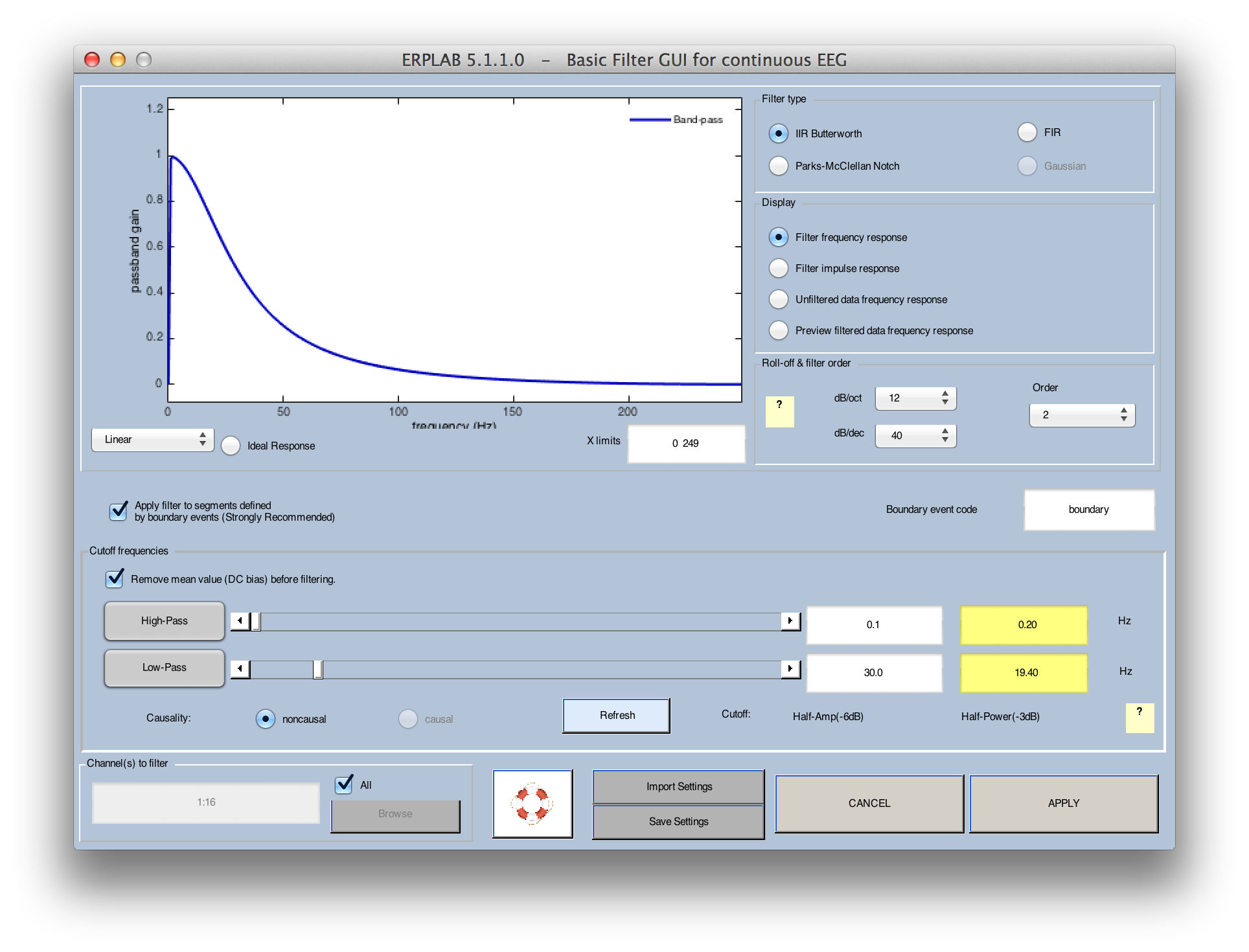
It is important to note that filters are a form of controlled distortion. The more heavily you filter your data, the more you are distorting the data (especially the time course of the ERP waveform). In many cases, mildly filtering the data removes a great deal of noise while causing minimal distortion of the data, making it very worthwhile. In most cognitive experiments, for example, you will increase your statistical power by filtering the low frequencies with a cutoff of ~0.1 Hz and by filtering the high frequencies with a cutoff of ~30 Hz. Using filters to obtain a narrower range of frequencies in the filtered data may severely distort your data, leading you to draw incorrect conclusions (for details, see Chapter 5 in Luck, 2005, An Introduction to the Event-Related Potential Technique). In addition, these distortions are usually worse for filters with steeper slopes. Thus, it is usually better to use relatively low-order filters and do not use a low cutoff of > 0.1 Hz or a high cutoff of < 20 Hz unless you have a good understanding of how filters operate in the time domain (i.e., how filtering operates as a convolution of the EEG/ERP waveform and the filter's impulse response function). For an example of how severe filtering can lead to unjustified conclusions, see Yeung et al., 2007, Psychophysiology, 44, 39-49. The settings shown in the screenshot above will be appropriate for most experiments.
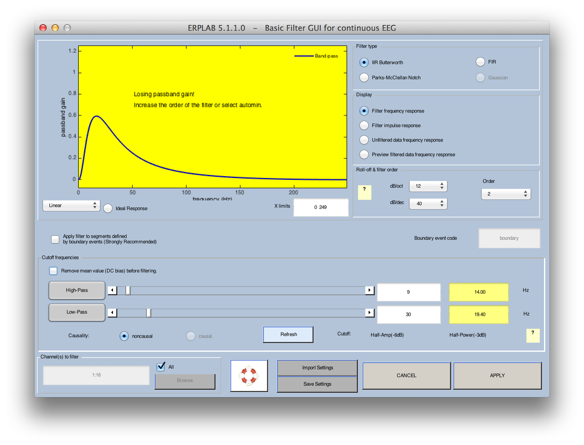
Some filter settings may lead to unintended consequences. For example, if you select a fairly high low cutoff and a fairly low high cutoff, the filter may end up causing significant attenuation at all frequencies. An example of this is shown in the screenshot below. When this happens, the background of the frequency response function changes colors and a warning message is shown. This problem can often be solved by using a higher-order filter (which will yield a steeper roll-off slope). In many cases, you will want to use the lowest order that does not create this problem of attenuation at all frequencies. You can either select a higher filter order manually or select automin for the order. If you select automin, the filtering routine will automatically determine the lowest order that will work for the selected filter cutoffs. This is what we recommend for most applications.
DC Offset
The filtering GUI contains an option to remove the DC offset before filtering. This can be useful if you have DC recordings and are using a high-pass filter (i.e., filtering out the low frequencies). If the EEG for a given recording session has a large DC offset, a high-pass filter will remove this offset by bringing the voltage down toward zero. This puts an artifact—which may be enormous—into your data during the period in which the voltage is being brought toward zero. This problem can be solved, at least in part, by simply subtracting the average voltage of the whole EEG waveform from each point in the waveform before filtering. This won't hurt if you do not have DC recordings, so it is active by default. This option is also available when you filter averaged ERPs and epoched EEG data, but it is generally not a good idea to remove the DC value in these cases (because the baseline subtraction that has already been done in these cases is usually a better way of removing any DC offsets).
Note for experts: ERPLAB uses the Matlab filtfilt() routine to implement the filters, which results in zero phase shift (non-causal filtering). This routine implements a very sophisticated scheme to deal with the fact that the waveform has a beginning and an end. That is, filtering the points at the beginning and end of the waveform requires using the undefined points prior to the beginning and after the end of the waveform, and filtfilt() has a way of dealing with these points. To be honest, we do not fully understand the algorithm. The best solution is usually to record several seconds of extra EEG at the beginning and end of each trial block so that there are no undefined points being used in the filtering of the time period you care about.
Filtering across data boundaries
Filters can also produce distortions if the DC offset changes suddenly. This can happen if you run multiple blocks of trials, separated by pauses during which the data are not saved in the EEG file. That is, if the DC offset gradually changes over time, and a period of time is missing from the EEG data, then a sudden change in offset will be present at the boundary between the nonconsecutive periods of the recording. This can also happen when several data individual datasets are concatenated into a single dataset. When the ERPLAB filter tools are applied to continuous EEG data, the filters are normally applied separately to segments of data defined by boundary events (see the section on boundary events). Thus, you should make sure that boundary events are present whenever there are discontinuities in the EEG data. You can disable this in the filtering GUI, in which case boundary events will be ignored and the filter will be applied to the entire file as if it was a continuous data set (not recommended unless you really know what you're doing!).
Filtering options
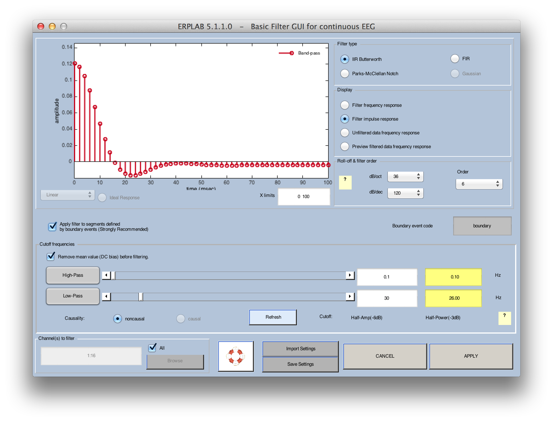
The filtering GUI allows you to select among 3 different types of filters. The first option is IIR Butterworth, which implements a digital version of a Butterworth infinite impulse response filter (run in both the forward and reverse directions to avoid a phase shift). This is a good general-purpose option. The second option is FIR, which uses a sinc-shaped finite impulse response function. When used with a relatively low order (e.g., 20), this will be a very mild filter that produces relatively little temporal spreading of the waveform. When used with a relatively high order (e.g., 200), it will produce a steep roll-off, but may induce artificial oscillations in the data. You can see this in the filter's impulse response function, which can be plotted instead of the frequency response function, as shown in the following screen shot. Note that only the right half of the impulse response function is shown (the filter is run twice, once in this direct and once in the opposite direction to avoid a phase shift).
The third filtering option is Parks-McClellan Notch, which implements a notch filter (e.g., a filter that attenuates frequencies near 60 Hz but not lower or higher frequencies). In most cases, we recommend using a high-pass filter at approximately 30 Hz rather than a notch filter to remove 60-Hz noise.