Epoching Bins - ucdavis/erplab GitHub Wiki
Epoching Bins
Once events have been assigned to bins, the next step is usually to convert the continuous EEG into a set of finite-duration "epochs" surrounding each of the event codes that will later be averaged into the various bins. When you select ERPLAB > Extract Bin-Based Epochs, you tell ERPLAB the time range to use when creating the epochs. Later, in the averaging step, all of the epochs in one bin will be averaged together. Note that you should not use EEGLAB's built-in epoching routine (Tools > Extract epochs) when you plan to use ERPLAB to average the data.
Note: You cannot ordinarily use data that have been epoched in EEGLAB with ERPLAB routines. Also, you cannot ordinarily run BINLISTER on epoched data. However, there is a trick that can sometimes work in these situations. Specifically, you can use ERPLAB > Utilities > Convert an epoched dataset into a continuous one to create a "fake" continuous dataset, with "boundary" events between the epochs. This doesn't always solve the problem, but it does in many cases.
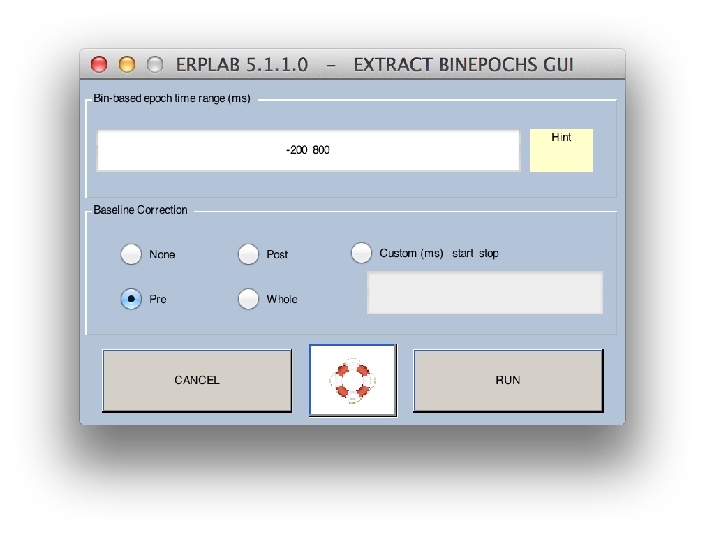
When you epoch the data, you will be given the option to perform baseline correction. The baseline correction process subtracts the mean prestimulus voltage (or the voltage over some other range that you specify) from the entire waveform for each channel in each epoch. This eliminates any overall voltage offset from the waveform in each epoch. In many ERP analysis systems, this is an absolutely essential step, because artifacts are rejected by determining whether the voltage in a given epoch exceeds some fixed value. If you don't first remove the overall voltage offset, many trials will exceed the threshold because of this voltage offset (which is not an artifact that requires rejection). In addition, the baseline correction step is typically used to avoid seeing the voltage offset when the data are plotted (which can also be accomplished with Plot channel data (scroll) > Display > Remove DC offset). In ERPLAB, baseline correction is needed only if you are using fixed voltage thresholds for artifact rejection; none of the other artifact rejection functions are influenced by voltage offsets. Also, all ERPLAB operations performed on the averaged waveforms that involve the baseline (including plotting) require that a baseline period be specified, which essentially causes baseline correction to be applied more explicitly (which is good for making sure you are aware that the baseline is relevant at every stage of processing). Thus, baseline correction during epoching is not as important in ERPLAB as in most other systems. However, it does no harm to perform baseline correction at the epoching stage, and it may eliminate confusion if the epoched data are later exported to another system. Thus, we recommend that you perform baseline correction during the epoching process unless you have a good reason not to. The epoching GUI looks like this:
Note: ERPLAB will convert the starting and ending times of the epoch that you specify in milliseconds into the corresponding sample points, but these may not be at exactly the millisecond values you specify. For example, if you sampled at 250 Hz (4 ms per sample), and you specified an epoch of -25 to +150 ms, the actual starting and ending points cannot be at -25 and +150 ms because there are no samples at these exact times (i.e., neither -25 nor +150 is an integer multiple of 4). ERPLAB will find the nearest sample points, which in this case would be -24 and +152 ms. Also, the number of sample points may not be what you expect. If, for example, you sample at 1000 Hz and specify an epoch of 0 to 1000 ms, this will actually end up being 1001 data points (because there are sample points at 0 ms, 1 ms, 2 ms, and so on up to and including 1000 ms). Information about exactly how ERPLAB selects a time window in this case can be found on the Timing Details page.
To epoch your data, follow these steps:
- Choose ERPLAB > Extract Bin-Based Epochs
- A window will appear in which you will enter a time range. Time zero will be the time of the time-locking event, and the time range must include time zero. For example, we may want an epoch that includes the points that fall between 200 ms prior and 800 ms after each event code. In this case, we would enter '-200 800' into the field.
- The Baseline correction option allows you to enable or disable baseline correction. If enabled, you can select the period that will be used for baseline correction. If you select Pre, the prestimulus baseline period will be used (this is the default). You could instead select Post to use the poststimulus period or Whole to select the entire epoch. Finally, you could select Custom and then provide two numbers that specify the beginning and end of the baseline period (e.g., -50 50 to use the interval from -50 ms to +50 ms). The baseline period must be entirely within the period of the epoch. For whatever period you select, the mean voltage over this period will be subtracted from the waveform for a each epoch (separately for each channel).
- You will then get the standard window for naming and saving the new dataset that will be created.
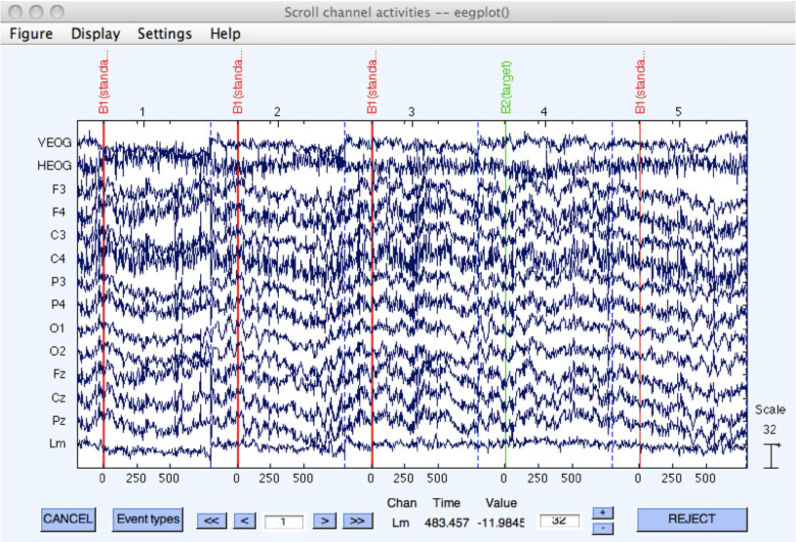
- If you would like to plot the epoched dataset, go to Plot > Channel data (scroll). Note that this EEGLAB function will plot multiple epochs side by side, with a dashed line separating adjacent epochs. This can be a little bit confusing, because it looks quite similar to a plot of continuous data (see screenshot below).
Note for experts: Internally, ERPLAB keeps track of which epochs in the epoched dataset correspond with which events in the EVENTLIST structure. This is how the flags for a given event in the EVENTLIST structure can be set when an artifact is detected in the corresponding epoch in the dataset. Most users do not need to know the details of this bookkeeping, but here is a brief description for experts. Each event in the EventList contains an EVENTLIST.eventinfo.item field, and this field indicates the item number of the event (e.g., first item, second item, etc.). This same information is stored in the EEG.event.item field and in the EEG.epoch.eventitem field (where it indicates the item number of the time-locking event, and the remaining associated events (if any) for each epoch). Thus, each time-locking event from the epoched EEG structure has an item number that matches exactly one of the items in the EVENTLIST structure. However, many items in the EVENTLIST structure do not have a matching item in the epoched EEG structure (because events that are not time-locking events, or were not included within the epoched window, have been eliminated from the epoched EEG structure but remain in the EVENTLIST structure).
The epoching process also replaces the event code labels in the EEG structure with a string that indicates the bin to which the epoch has been assigned (see screenshot above). The original event code or event label is also provided (in parentheses) for your information. For example, if an event code of 100 was assigned to Bin 1, the label for this event code would be changed to B1(100). If a given event code is assigned to multiple bins, the bins are separated by commas. That is, if an event code of 100 was assigned to Bins 1 and 7, the label for this event code would be changed to B1,7(100). If you have defined labels for your event codes, these labels are used instead of event codes (e.g., B1,7(target)). These bin labels are used during the averaging process, so you should not change them. Once you have epoched your data, you cannot replace these bin labels with event codes or event labels using ERPLAB > Transfer eventinfo to EEG.type.