ERPLAB Studio: Filtering Overview - ucdavis/erplab GitHub Wiki
Filtering is a complex and often poorly understood and incorrectly used aspect of EEG and ERP processing, and ERPLAB is designed to make it easy for users to filter their data properly. For more information about how filters work, see Chapter 7 in An Introduction to the Event-Related Potential Technique and Chapter 4 in Applied Event-Related Potential Data Analysis.
If you are using the ERPLAB Studio GUI, you will see a Filtering panel in both the EEG tab and the ERP tab. These panels are nearly identical, but there are a few small differences between filtering continuous EEG, epoched EEG, or averaged ERPs (as discussed below).
Unless you specify otherwise using the Advanced button, ERPLAB uses bidirectional (noncausal) Butterworth IIR filters. These filters are efficient and create no phase shift.
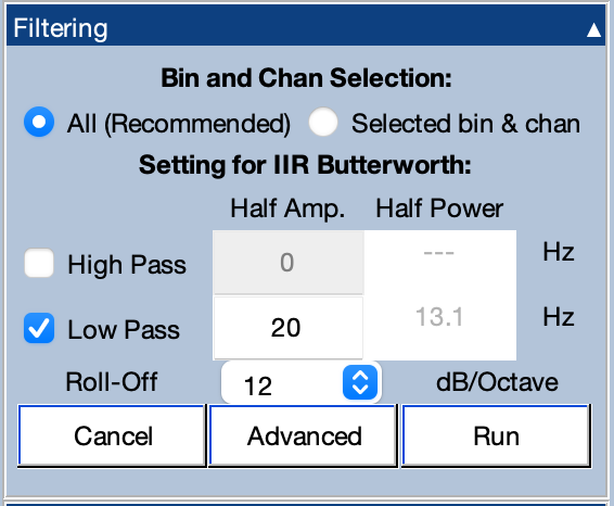
To filter an EEGset or ERPset, you simply select the low-pass cutoff frequency and/or high-pass cutoff frequency along with the roll-off, and click Run. A new EEGset or ERPset will then be created with the filtered data. Note that you will specify the half-amplitude cutoff frequency (the frequency at which the signal is reduced by 6 dB), and the panel will show you the corresponding half-power frequency (the frequency at which the signal is reduced by 3 dB).
It is possible to limit the filtering to a subset of the channels in an EEGset or a subset of the bins and channels in an ERPset, but you will typically want to filter all bins and channels in the same way.
You can view the properties of the filter by selecting the cutoff frequencies and roll-off and then clicking the Advanced button. By default, the frequency response function is shown.
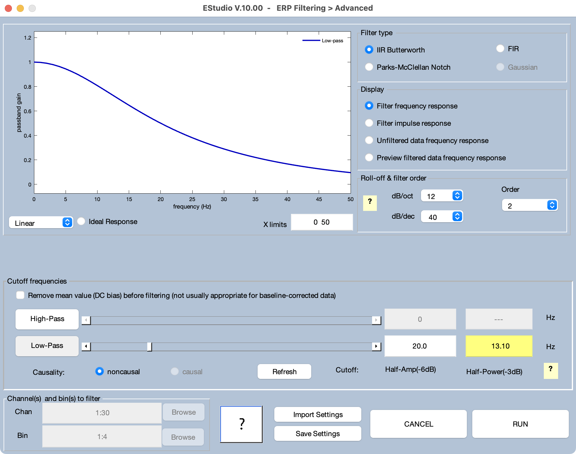
You can see the filter's impulse response function by selecting Filter impulse response.
If you click the Advanced button, you will be able to choose from among three classes of filters: 1) Infinite impulse response (IIR) Butterworth filters; 2) Finite impulse response (FIR) filters; and 3) Parks-McClellan notch filters. The FIR filters are rather limited at present, and we recommend using the Butterworth filters for most low-pass, high-pass, and bandpass applications. The Parks-McClellan filters can be used when a notch filter is needed. The IIR and FIR filters are applied in both directions to produce a zero phase-shift, noncausal filter.
It is important to note that filters are a form of controlled distortion. The more heavily you filter your data, the more you are distorting the data (especially the time course of the ERP waveform). In many cases, mildly filtering the data removes a great deal of noise while causing minimal distortion of the data, making it very worthwhile. In most cognitive experiments, for example, you will increase your statistical power by filtering the low frequencies with a cutoff of ~0.1 Hz and by filtering the high frequencies with a cutoff of ~30 Hz (click here (Zhang et al., 2024 a) for a paper describing optimal filter settings for a broad range of ERP paradigms and click here (Zhang et al., 2024 b) for a paper describing how you can determine the optimal filter settings for your own data).
Using filters to obtain a narrower range of frequencies in the filtered data may severely distort your data, leading you to draw incorrect conclusions (see, e.g., Tanner et al., 2015). In addition, these distortions are usually worse for filters with steeper slopes. Thus, it is usually better to use relatively low-order filters and avoid cuttos of > 0.1 Hz unless you really know what you're doing. For an example of how severe filtering can lead to unjustified conclusions, see Yeung et al. (2007).
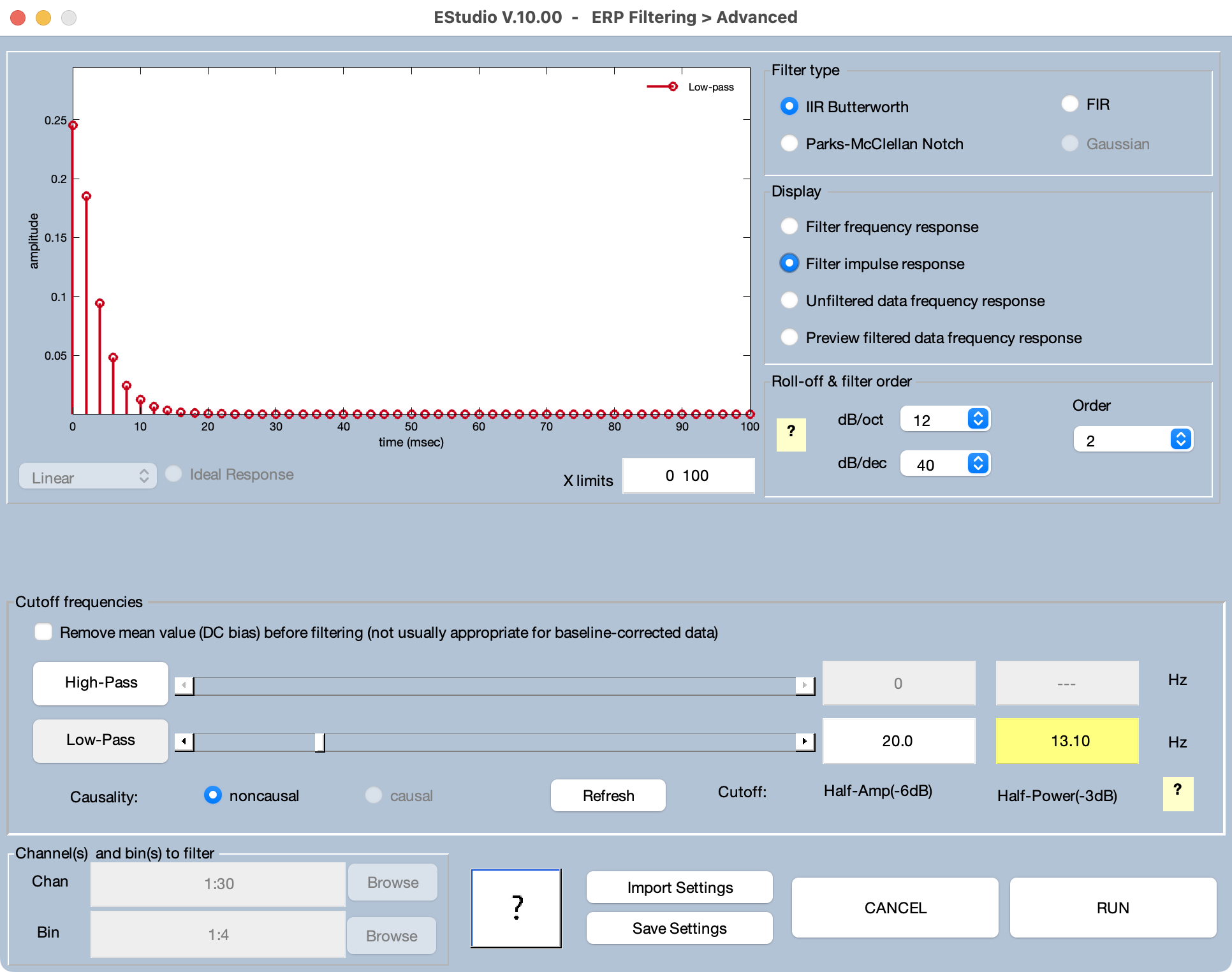
Some filter settings may lead to unintended consequences. For example, if you select a fairly high low cutoff and a fairly low high cutoff, the filter may end up causing significant attenuation at all frequencies. An example of this is shown in the screenshot below.
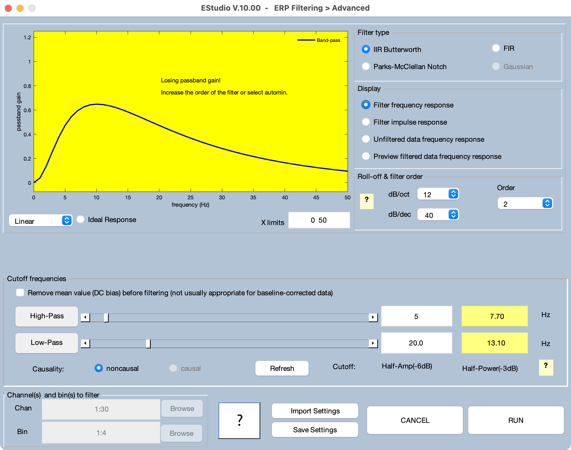
When this happens, the background of the frequency response function changes colors and a warning message is shown. This problem can often be solved by using a higher-order filter (which will yield a steeper roll-off slope). You can either select a higher filter order manually or select automin for the order. If you select automin, the filtering routine will automatically determine the lowest order that will work for the selected filter cutoffs. However, higher filter orders tend to cause more temporal distortion, so the best solution is usually to avoid specifying a narrow band of frequencies.
The filters used by most EEG/ERP processing systems (including ERPLAB) use time points before the beginning of the actual data and after the end of the actual data. The voltages at these time points are undefined, and many systems treat these points as having an amplitude of zero microvolts. This can create artifacts at the beginning and end of the sequence of data points (edge artifacts).
ERPLAB uses the Matlab filtfilt() routine to implement the filters, which implements a very sophisticated scheme that essentially extrapolates the data beyond the beginning and end points. This minimizes the edge artifacts.
However, this extrapolation does not always work well if the EEG signal has a large DC offset, which produces a large discontinuity in voltage between the time points in the actual data and the time points before and after the data. If your data have not already been high-pass filtered, we recommend selecting the Remove DC Offset option before filtering. Ordinarily, this option should be used only for continuous EEG data, not for epoched EEG or averaged ERPs. In fact, this option is not available in the Filtering panel unless the dataset contains continuous EEG (but it is always available by clicking the Advanced button).
To minimize edge artifacts in your continuous EEG, we recommend recording several seconds of extra EEG at the beginning and end of each trial block. That way, any artifacts will be over before your events begin.
Filters can also produce distortions if the DC offset changes suddenly. This can happen if you run multiple blocks of trials, separated by pauses during which the data are not saved in the EEG file. That is, if the DC offset gradually changes over time, and a period of time is missing from the EEG data, then a sudden change in offset will be present at the boundary between the nonconsecutive periods of the recording. This can also happen when several data individual datasets are concatenated into a single dataset or when sections of data containing large artifacts are deleted from the continuous EEG. In all of these cases, a boundary event code will be placed in the dataset at the time of the discontinuity (see the section on boundary events).
By default, ERPLAB's filters will be applied separately to segments of data defined by boundary events. You can disable this in the Advanced window, in which case boundary events will be ignored and the filter will be applied to the entire file as if it was a continuous data set (not recommended unless you really know what you're doing!).