ERPLAB Studio Panels: Artifact Detection in Epoched EEG - ucdavis/erplab GitHub Wiki
Artifacts can be detected in epoched EEGsets using the Artifact Detection panel in the EEG tab. This panel uses either visual inspection (manual artifact detection) or automated algorithms to "mark" epochs containing artifacts. The marked epochs still remain in the dataset, but they are excluded when averaged ERPs are created (unless you tell the averaging routine to include them). If an artifact is confined to a single channel, you may instead interpolate the voltages for the channel in epochs containing artifacts using the Interpolate marked epochs option in the Interpolate Channels panel.
EEGLAB has additional artifact detection routines that can be accessed by launching EEGLAB directly. If you use those routines, you will need to synchronize the artifact marks (see the section on sychronization below).
ERPLAB contains several different automated artifact detection functions that are optimized for detecting different types of artifact (e.g., blinks, eye movements, EMG bursts, etc.). To determine whether an EEG epoch contains an artifact, a function is applied to the data from that epoch. This function returns a value, which is related to the strength of evidence for the presence of a specific artifact in that epoch. This value is then compared with a threshold, and the epoch is marked for rejection if the value exceeds the threshold. The function is applied to a single channel at a time, and information is retained in the EEGset indicating which channels contained artifacts in each epoch. However, the entire epoch is excluded from the ERP averages if one or more channels contains an artifact. It is not currently possible to exclude only some channels from a given epoch.
You would typically run the artifact detection routines multiple times for a given participant, each time focusing on a different type of artifact. For example, you might run it once on the VEOG channel with parameters designed to detect blinks, once on the HEOG channel uwith parameters designed to detect horizontal eye movements, and once on all EEG channels with parameters designed to detect large miscellaneous voltage deflections. Each time you run it, the flags can be combined with the flags from the previous run. You can clear the flags at any time (see the section on Clearing Artifact Marks below).
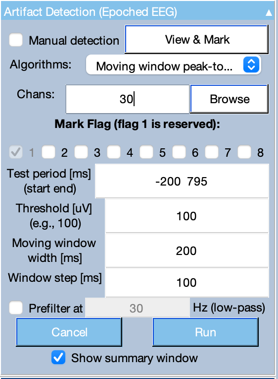
The Artifact Detection panel is shown below. The popup menu at the top is used to determine which general algorithm will be used to quantify the strength of evidence that an artifact is present. The algorithms are described in the next subsection. This algorithm is applied to the channel(s) specified in the Chans box. You may simply list the channels, separated by spaces (e.g., 12 13 14 15 20 21 22 23), and you can also use the colon characters to specify ranges of channels (e.g., 12:15 20:23). The algorithm is applied to the data within the time range specified in the Test period box. This test period can be the entire epoch length or just a subset, but it cannot extend beyond the epoch. For details about time window specifications, see the page on Timing Details.
The threshold for rejection is specified in the Threshold box. In the example shown in the screenshot below, the moving window peak-to-peak amplitude will be measured from channel 30 between -200 and 795 ms in each epoch, and the epoch will be marked for rejection if this amplitude exceeds 100 µV.
Setting Flags. When an artifact is detected, the reject field of the EEG structure is updated (in the EEG.reject.rejmanual and EEG.reject.rejmanualE fields), and the artifact flags in the EVENTLIST is also updated. Flag 1 (the least significnt bit) is set for any artifact, but you can also choose to set additional flags in the Mark flags section of the panel. For example, you could set Flag 2 for any epochs that contain a blink in the VEOG channel, Flag 3 for any epochs that contain an eye movement in the HEOG channel, and Flag 4 for any epochs that contain large noise deflections in any channel. More than one flag can be set for a given epoch. The flags allow you to keep a count of the number of artifacts of each type. They can also be used in combination with BINLISTER to create bins in which a given kind of artifact did or did not occur.
Prefiltering. When the signal contains a lot of high-frequency noise, and you are trying to detect a more slowly-changing signal (e.g., a blink in the presence of EMG noise), the noise can cause the threshold to be exceeded and produce a lot of false alarms. This can be minimized by selecting the Prefilter option. This option creates a copy of the EEGset, filters it with the specified low-pass cutoff, and tests for artifacts in this filtered copy. The artifact information is then transferred to the original EEGset (i.e., the filtering is not applied to the EEGset that is output by the function). This is particularly useful for the moving window peak-to-peak amplitude algorithm and the simple voltage threshold algorithm. It is not usually recommended for the other algorithms.
Additional parameters. There are other fields in the Artifact Detection panel that vary depending on which artifact detection algorithm is used (as described in the next section).
The artifact flags allow you to count how many artifacts of each type were present. This information is shown after an artifact detection algorithm runs if the Show summary window option is selected in the Artifact Detection panel. This information is saved in the EventList, so you can also view it later with the tools in the Artifact Info & Tools panel (for an EEGset) or the ERP & Bin Information panel (for an ERPset, which contains a copy of the EventList). The Artifact Info & Tools panel also lets you clear the flags.
When the epoched EEG is plotted in the main ERPLAB Studio window, epochs will be shown with a yellow background if the EEG.reject field is set, and any channels that were responsible for the artifact will be shown in a thicker line.
Moving Window Peak-to-Peak Amplitude. This function is useful for detecting blinks or other brief voltage deflections (e.g., EMG bursts). Peak-to-peak amplitude is the difference between the most positive and most negative voltages within a window. A moving window peak-to-peak amplitude function computes the peak-to-peak amplitude within a series of windows within each epoch. For example, if your epoch goes from -200 to +795 ms, you could select a window size of 200 ms and a step size of 20 ms. For each epoch, the routine would calculate the peak-to-peak voltage from -200 to 0 ms, from -180 to +20 ms, from -160 to +40 ms, etc. The routine would find the largest peak-to-peak amplitude from these windows for a given epoch of data, compare that largest value with a threshold value, and mark the trial for rejection if the largest value exceeds the threshold.
The Moving window full width (ms) is the width of the moving window (e.g., 200 ms in the example from the previous paragraph). The Window Step (ms) value is the size of the step between successive windows. In most cases, we recommend a step size that is 50% of the moving window width. A smaller step size will make the routine run more slowly.
Simple Voltage Threshold. This algorithm is useful for detecting large, miscellaneous voltage deflections (e.g., movement artifacts). It simply determines whether the voltage at any point in the test period exceeds a threshold. You specify two numbers for the threshold, a lower bound and an upper bound. Usually these bounds are symmetrical (e.g., -100 100 to mark epochs were the voltage goes beyond the range of -100 to +100 µV), but you can use asymmetrical bounds if desired (e.g., -1000 100 if you were primarily interested in detecting small positive-going voltage deflections).
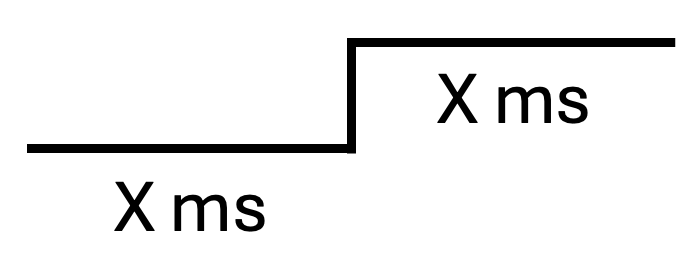
Step-Like Artifacts. This algorithm was originally designed to detect the step-like changes in voltage that are produced when subjects make saccadic eye movements, but it is also typically the best algorithm for detecting blinks. The step function begins by defining a step-shaped function of a particular width (e.g., 100 ms at one voltage and then 100 ms at a different voltage). An example step function is shown below. It then scans the test period for this step-like shape across a set of moving windows.
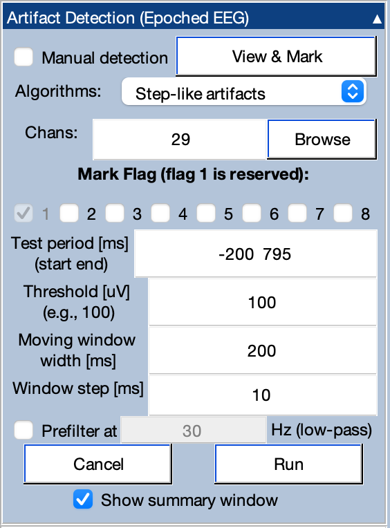
The width of the moving window is set in the Moving window width box. Note that this is the full window width (e.g., a value of 200 would be used for a step function that is 100 ms before and 100 ms after the voltage transition). The Window Step controls how much the moving window is shifted on each step. For detecting subtle artifacts, such as small eye movements, a small window step is preferable (e.g., 10 ms). However, smaller window step values will make the routine run more slowly. The screenshot below shows typical parameters for finding eye movements in a horizontal EOG channel. Note that we do not recommend applying a Prefilter when using this algorithm.
There are two ways of thinking about how the step function works. In one conceptualization, the covariance between the step function and the data is computed in each step, providing a measure of the extent to which that segment of data looks like a large voltage step. This is done across the entire Test Period, and the epoch is rejected if the largest covariance is greater than the rejection threshold. It turns out that this is computationally identical to taking the mean voltage from the first half of the step and subtracting it from the mean voltage from the second half. That is, the mean voltage between -200 and -100 ms would be subtracted from the mean voltage between -100 and 0 ms. Then the mean voltage between -190 to -90 ms would be subtracted from the mean voltage between -90 and +10 ms. This would be done for each interval through out the Test Period, and the largest of these voltage differences is compared with the rejection threshold to determine whether the present epoch should be marked for rejection.
Sample-to-Sample Voltage. This algorithm finds sudden shifts in voltage between one sample and the next. You simply select the threshold, and it rejects any epochs in which the difference in voltage between consecutive sample points exceeds this threshold. Note that we do not recommend applying a Prefilter when using this algorithm.
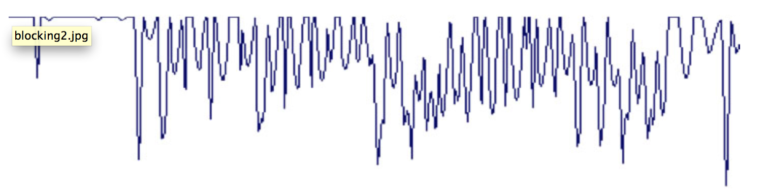
Blocking and Flat Line. This algorithm is designed to find periods of "blocking" (saturation or flatlining of the amplifier or analog-to-digital converter). Here's what blocking typically looks like in an EEG recording:
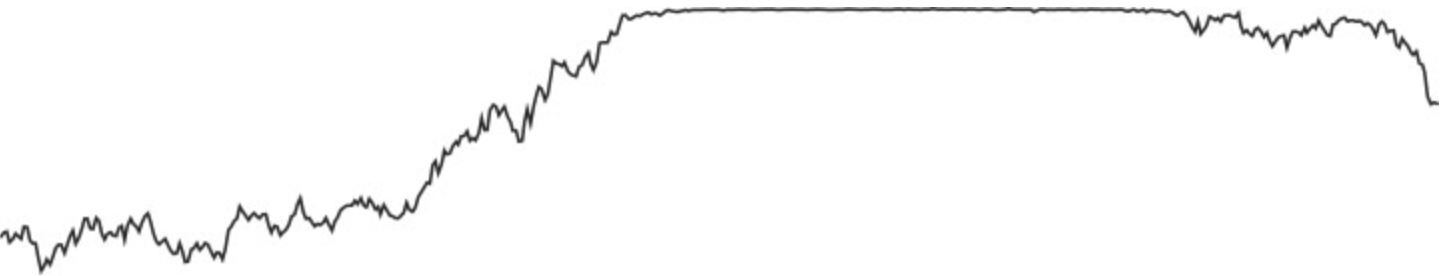
You might think you could detect this sort of flatline pattern just by looking for periods during which the voltage remains constant over a period of time. However, due to noise, the voltage may not be exactly constant. Also, it may go back and forth between the flatline value and non-flatlined values, as in this example:
Thus, we use the following algorithm (originally developed by Jon Hansen for ERPSS):
- Find the most positive voltage in the epoch
- Determine how many time points are within delta µV of this maximum voltage. This value is entered the Amplitude tolerance box in the panel. The number of time points is used to determine the duration of the blocking (duration in milliseconds = time points x sample duration). The time points are summed together even if they are not consecutive.
- Do the same thing for the most negative voltage in the epoch.
- Take the longer the two durations (one for positive, one for negative) and compare it against the Flat line duration value specified in the panel. If the longer duration is greater than the Flat line duration value, the epoch is marked for rejection.
The optimal Amplitude tolerance and Flat line duration values will depend on the nature of your system. Typical values might be 1 µV for the tolerance and 200 ms for the duration. This would lead to the rejection of any epochs in which more than 200 ms worth of points are within 1 µV of the maximum (or minimum) voltage in the epoch.
Artifacts can also be manually marked for rejection (or unmarked) by selecting the Manual Detection option, selecting which flags should be set for manually marked epochs, and then clicking View & Mark. This will cause a window to appear that shows each epoch. You can click on an epoch to mark it, which will give that epoch a yellow background. If you click on a marked epoch, it will become unmarked.
Once you are done selecting which epochs should be marked, click the Mark button, and then the selected epochs will become marked. Note that all channels in an epoch will be marked as containing artifacts when the epoch is manually marked.
Note that the rest of ERPLAB Studio will be “frozen” while you are viewing the window to select epochs for marking.
A slight complication arises when EEGLAB's artifact detection tools are used in combination with ERPLAB. Specifically, because EEGLAB doesn't "know" anything about the artifact flags in the EVENTLIST structure, the EEGLAB artifact detection tools do not update the artifact flags in the EVENTLIST structure. In addition, if you manually change the artifact flags in the EventList structure (e.g., with a script or by editing a text version of the EventList structure), these changes will not be automatically propagated to EEG.reject. In these cases, you can synchronize the information in the EventList flags and in EEG.reject by going to the Artifact Info & Tools panel and clicking Sync artifact info in EEG and EVENTLIST. In addition, when you create averaged ERPs from epoched EEG, ERPLAB will automatically check for any differences between the EventList flags and EEG.reject; if it detects any differences, it will give you the opportunity to synchronize before averaging.
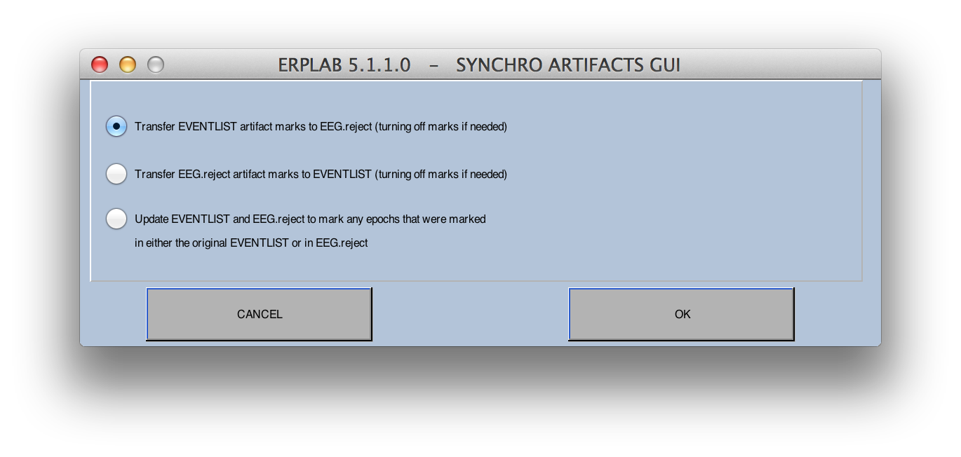
When you synchronize the artifact information, you will see the options shown in the screenshot below. You can either completely replace the artifact marks in the EVENTLIST with EEGLAB's artifact marks, completely replace EEGLAB's artifact marks with the artifacts in the EVENLIST, or merge them so that any events marked with artifacts in either list will be marked in both lists. If you do something that turns off previous artifact marks (e.g., with EEGLAB's artifact detection tools), you should use one of the first two options; otherwise no marks will be turned off.
You can clear the artifact marks in an EEGset by going to the Artifact Info & Tools panel and clicking the Clear artifact detection marks on EEG button. This will bring up the window shown in the screenshot below. The Reset Artifact Detection Marks option in the EEGLAB portion of the window clears the marks in EEGLAB's record of marks (the reject field of the EEG structure). The Reset Flags option in the ERPLAB portion of the window clears the marks in ERPLAB's record of marks (the artifact flags of the EVENTLIST structure). Ordinarily you will set both options.
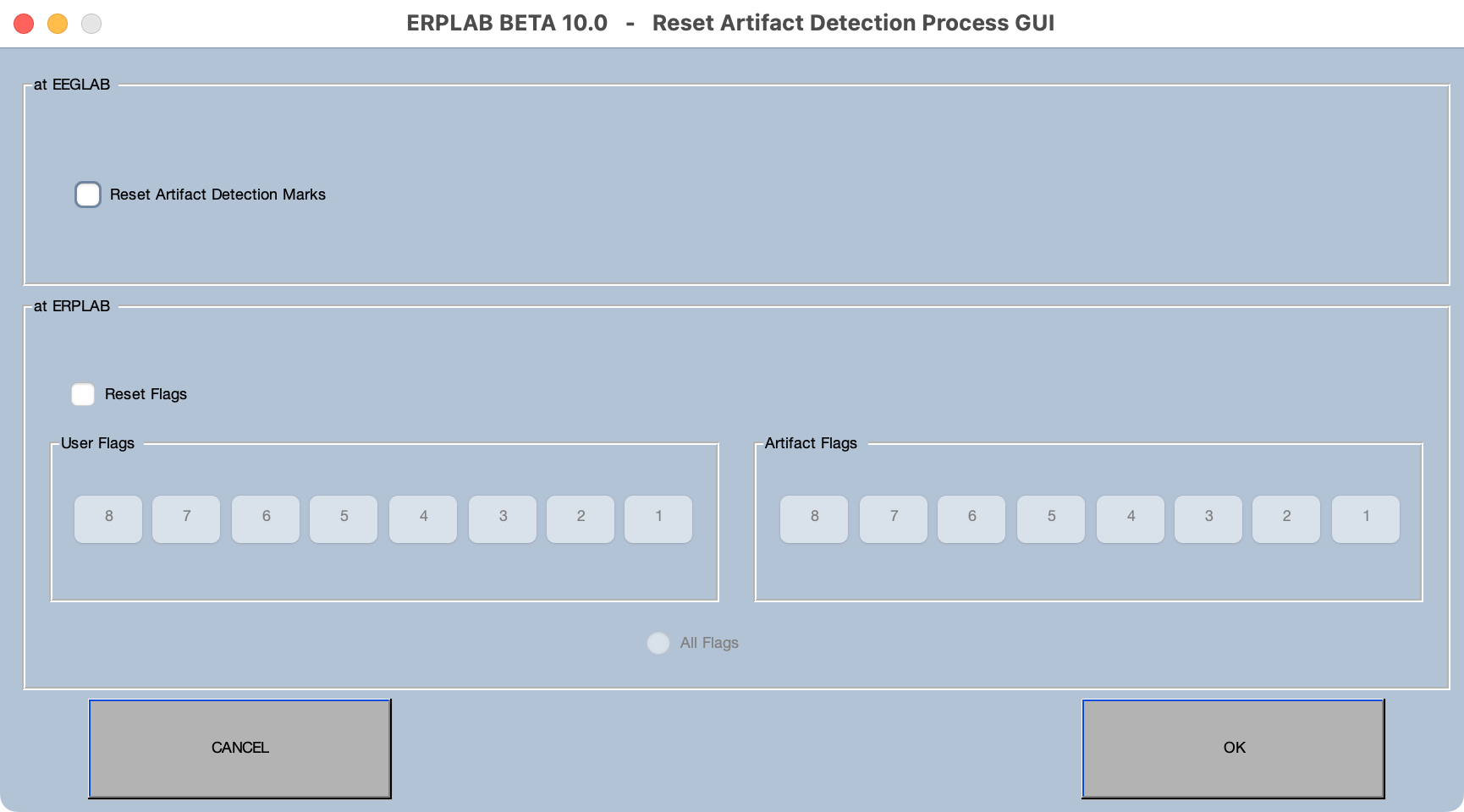
Note that, if desired, you can clear only a subset of the ERPLAB flags. For example, if you use different flags for blinks and horizontal eye movements, you could clear one but not the other.
If an artifact is limited to a single channel (e.g., an electrode that occasionally goes "bad"), you can interpolate that channel on trials with artifacts rather than rejecting those trials. To do this, you must make sure to set a distinct flag for that artifact. For example, if Channel 12 has occasional large artifacts, you could use the moving window peak-to-peak algorithm with a threshold of perhaps 200 or 300, marking Flag 8 when this artifact occurs.
Then, you can go to the Interpolate Channels panel (in the EEG tab), enter 12 as the Interpolated chan (and possibly list some channels to ignore, such as bipolar VEOG channels). You'll then select Interpolate marked epochs to interpolate only the epochs marked as containing artifacts. If you have other kinds of artifacts marked as well, you need to tell it to interpolate only epochs with Flag 8 set. You do this by clicking the Advanced button.
After performing the interpolation, you must clear Flag 8 (see Clearing Artifact Marks above). If you don't the epochs containing this artifact will be excluded from ERP averaging.