IoT - ttulka/technologies GitHub Wiki
LoRa and LoRaWAN
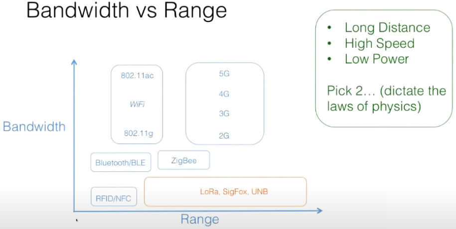
LoRa = Wireless modulation technology on the physical layer for low-power, wide area networks (LPWANs) developed by Semtech
LoRaWAN = Communication protocol on the LoRa phy. (analog to the IP layer) - data packets, encryption, etc.
- Open source protocol developed by the LoRa Alliance
- Aims to securely connect LoRa devices to the internet
- Asynchronous, ALOHA-based protocol, which means an end-device can sleep for as little or as long as the application desires
- For applications that need a very long battery lifetime and optimized cost, but do not need to communicate as often
LoRA PHY
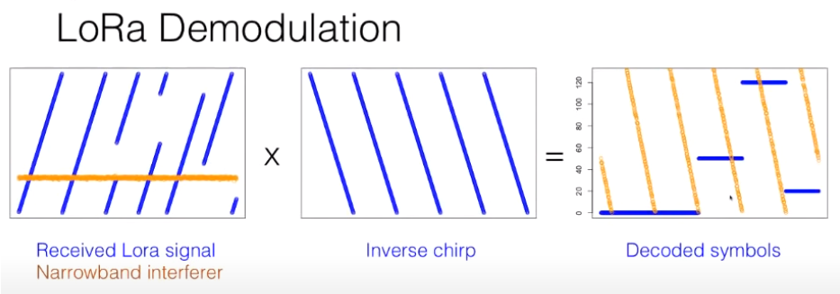
LoRa is a proprietary spread spectrum modulation scheme that is based on Chirp Spread Spectrum (CSS) modulation.
Spread spectrum techniques spread the signal deliberately in the frequency domain.
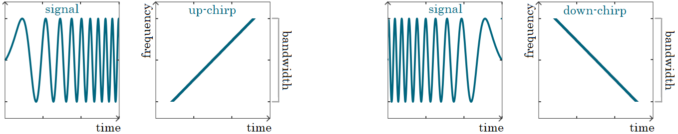
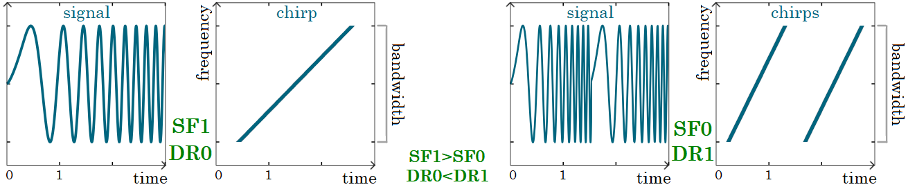
A chirp (sweep signal) is a tone in which the frequency increases (up-chirp) or decreases (down-chirp) with time.
Chirp Spread Spectrum is a spread spectrum technique that uses wideband linear frequency modulated chirp pulses to encode information.
Limits
- Bandwidth 250 bits per sec (low bandwidth => low energy)
- Only 1 % of the bandwidth is allowed to be used by a single device => max bandwidth per device is 2.5 bps
- Link budget in EU is ca 150 dB at 800 km (free space)
- LoRa offers a trade-off between sensitivity and data rate, while operating in a fixed-bandwidth channel of either 125 KHz or 500 KHz (for uplink channels), and 500 KHz (for downlink channels)
- Adaptive optimizations of an individual end node’s power levels and data rates
- For example, an end device located close to a gateway should transmit data at a low spreading factor, since very little link budget is needed.
- Higher spreading factor provides increased processing gain, and higher reception sensitivity, although the data rate will, necessarily, be lower
Time on air (ToA) / Dwell Time - When a signal is sent from a sender it takes a certain amount of time before a receiver receives this signal.
Duty cycle is the proportion of time during which a component, device, or system is operated. The duty cycle can be expressed as a ratio or as a percentage. Example: Duty cycle = 1%, ToA = 530ms => after sending a message, we have to wait 99x530ms = 52.47s before sending a new message.
Bandwidth (BW) is the amount of radio spectrum used for the transmission of a signal. The more bandwidth used, the more of the spectrum is used to transmit the data. This makes it easier for the receiver to distinguish the signal from the noise. Therefore, a wider bandwidth has a longer range than a narrower bandwidth.
Bandwidth is defined as the difference between the highest and the lowest frequencies of a signal generated.
A LoRa gateway and a corresponding end device must use the same channel bandwidth. 125 kHz is most commonly used; however, there are also channels at 250 kHz and at 500 kHz as well.
Coding Rate is the parameter that defines how much extra data we send to describe the same information. If we send a message of 12 bytes, and use a coding rate of 4/5, for every 4 bits of information, we send 5 bits of data.
The extra data, called Forward Error Correction (FEC), makes it possible to automatically correct bit errors or symbol errors that occur during the reception of the packet.
LoRaWAN has four possible coding rates: 4/5, 4/6, 4/7, and 4/8. When we use the 4/8 coding rate, we send two bits for every one bit of real data; in essence, we send the message twice.
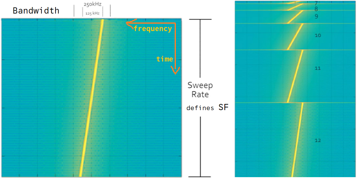
Spreading factor (SF) is the speed at which we spread the data across the bandwidth of a radio channel.
- The slower the data is sent, the easier it becomes to receive the signal.
- The larger the spreading factor used, the farther the signal will be able to travel and still be received without errors by the RF receiver.
- Larger SF means longer time on air => lower DR
- SF is based on the Sweep Rate, which determines the speed at which the controller increases or decreases the frequency.
- Larger SF means slower data which means higher energy consumption
Lowering the spreading factor makes it more difficult for the gateway to receive a transmission, as it will be more sensitive to noise.
Data rate (DR) - the amount of bits that are processed per unit of time. It's a combination of both BW and SF.
- High DR means a small SF and high probability of packet loss
- Low DR means longer time on air, more power consumption, longer range, and reduced gateway capacity (it keeps channels utilized)
LoRa packets using different data rates are orthogonal, meaning that they are invisible to each other: they simply appear as noise to one another.
If you increase the data rate (make the bandwidth wider or the spreading factor lower) you can transmit the same number of bytes in a shorter time.
| Data Rate | Spreding Factor | BW/TXPower | bit rate | range | battery life |
|---|---|---|---|---|---|
| DR0 | SF12 | 125 kHz | 250 bit/s | 12 km | 138 days |
| DR1 | SF11 | 125 kHz | 440 bit/s | 10 km | |
| DR2 | SF10 | 125 kHz | 980 bit/s | 8 km | |
| DR3 | SF9 | 125 kHz | 1760 bit/s | 6 km | 275 days |
| DR4 | SF8 | 125 kHz | 3125 bit/s | 4 km | |
| DR5 | SF7 | 125 kHz | 5470 bit/s | 2 km | 317 days |
| DR6 | SF7 | 250 kHz | 11000 bit/s | 2 km | 284 days |
LoRaWAN
Components: End-devices, Gateways, Network Server, Application Server, Join Server
Packets
Uplink packets are sent by end-devices to a Network Server relayed by one or many gateways.
Downlink packets are sent by a Network Server to only one end-device and are transmitted by a Network Server through one or more gateways.
All LoRaWAN uplink and downlink packets carry a PHY payload (PHYPayload) starting with a single-octet MAC header (MHDR), followed by a MAC payload (MACPayload), and ending with a 4-octet message integrity code (MIC).
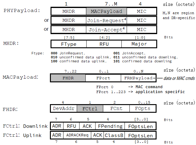
Join-Request and Join-Accept frames are used by the over-the-air activation procedure.
Data frames transfer application data or MAC commands, which can be combined into a single frame.
Retransmission
The delay between retransmissions is at the discretion of the end-device and may be different for each end-device. When an end-device has requested an ACK from the Network but has not yet received it, it shall wait RETRANSMIT_TIMEOUT seconds after RECEIVE_DELAY2 seconds have elapsed after the end of the previous uplink transmission before sending a new uplink (repetition or new frame).
MAC Commands
For network administration, a set of MAC commands may be exchanged exclusively between a Network Server and the MAC layer of an end-device. MAC layer commands are never visible to the Application Server, nor to the application running on the end-device.
A single data frame may contain any sequence of MAC commands, either piggybacked in the FOpts field or, when sent as a separate data frame, in the FRMPayload field with the FPort field set to 0.
A MAC command consists of a command identifier (CID) of 1 octet followed by a possibly empty command-specific sequence of octets.
| CID | Command | Transmitted by | Description |
|---|---|---|---|
| 0x02 | LinkCheckReq | end-device | validates its connectivity to a network |
| 0x02 | LinkCheckAns | network server | contains info about link margin |
| 0x03 | LinkADRReq | network server | ADR request |
| 0x03 | LinkADRAns | end-device | acknowledges LinkADRReq |
| 0x04 | DutyCycleReq | network server | sets the maximum transmit duty cycle |
| 0x04 | DutyCycleAns | end-device | acknowledges DutyCycleReq |
| 0x05 | RXParamSetupReq | network server | sets the reception slot parameters |
| 0x05 | RXParamSetupAns | end-device | acknowledges RXParamSetupReq |
| 0x06 | DevStatusReq | network server | requests the status of the end-device |
| 0x06 | DevStatusAns | end-device | with battery level and radio status |
| 0x07 | NewChannelReq | network server | manages definition of a radio channel |
| 0x07 | NewChannelAns | end-device | acknowledges NewChannelReq |
| 0x08 | RXTimingSetupReq | network server | sets the timing of the reception slots |
| 0x08 | RXTimingSetupAns | end-device | acknowledges RXTimingSetupReq |
| 0x03 | TXParamSetupReq | network server | sets allowed dwell time and MaxEIRP |
| 0x03 | TXParamSetupAns | end-device | acknowledges TXParamSetupReq |
| 0x03 | DlChannelReq | network server | sets up downlink RX1 |
| 0x03 | DlChannelAns | end-device | acknowledges DlChannelReq |
| 0x03 | DeviceTimeReq | end-device | requests the current GPS time |
| 0x03 | DeviceTimeAns | network server | answers DeviceTimeReq |
Adaptive Data Rate (ADR)
Adaptive Data Rate (ADR) is the capability of the network to automatically optimize the speed in which the devices send their data.
- changes the data rate based on simple rules:
- if the strength of the radio signal (called the link margin) is high, the data rate can be increased;
- if the link margin is low, the data rate can be lowered.
- The Network Server, which received the data, selects the ideal data rate based on the received signals strength (link margin)
- The data rate the node should use is sent via a downlink to the device.
- Mobile devices cannot use ADR!
- For moving devices we can use Blind ADR (or Application Driven ADR) where the application defines several data rates, used over time (eg. 1 uplink using SF7 every 30 minutes, 1 uplink at SF10 every 6 hours and 1 uplink at SF12 every day)
LoRaWAN allows end-devices to use any of the possible data rates (DR) and transmission power (TX) individually. This feature is used by Network Servers to adapt and optimize the number of retransmissions, the data rate, and the TX power of end-devices. This is referred to as the adaptive data rate (ADR) and, when it is enabled, end-devices will be optimized to use the fastest data rate and minimum TX power possible.
When the downlink ADR bit is set, it informs the end-device that the Network Server is able to send ADR commands. The end-device may set/unset the uplink ADR bit independently.
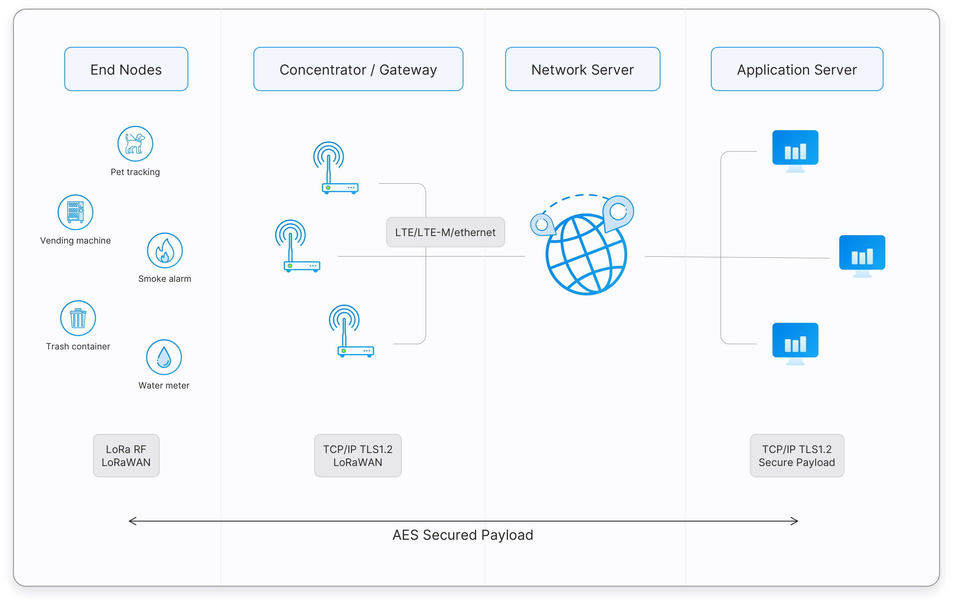
End Devices
Consist of a MicroController Unit (MCU), power supply, peripherals such as sensors, the LoRa radio (modem) and antenna.
LoRaWAN stack can run 1. embedded in the application layer on MCU, 2. on the LoRa modem on a tiny separated MCU, 3. in the LoRa module with the application code on MCU.
Classes
Classes of LoRaWAN devices: A, B, C (downlink - message from the network, uplink - message from the device)
- Class A: low power consumption, sleeping most of the time, can receive a downlink only as a response to an uplink just sent - only the end-device can initiate communication. Fire alarms, flood detectors.
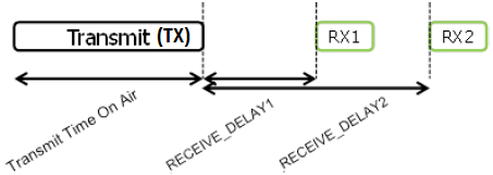
- Class A end-devices allow bi-directional communications, whereby each end-device's uplink transmission is followed by two short downlink receive windows.
- Class B: average battery life, listen to the network periodically to receive a downlink and also after sending an uplink. Metering temperature etc.
- Class C: high power consumption, continuously listening to the network downlinks (no latency) except when sending uplinks. Traffic monitoring and near-real-time apps.
End-Device Activation
Activation of an end-device can be achieved in two ways, either via Over-The-Air Activation (OTAA) when an end-device is deployed or reset, or via Activation By Personalization (ABP) in which the two steps of end-device personalization and activation are performed in one step.
After activation, a device address (DevAddr), a network session key (NwkSKey), and an application session key (AppSKey) are stored in the end-device.
End-device address (DevAddr)
DevAddr consists of 32 bits and identifies the end-device within the current network; is allocated by the Network Server of the end-device.
Network session key (NwkSKey)
NwkSKey is a network session key specific to the end-device. It is used by both the Network Server and the end-device to calculate and verify the MIC (message integrity code) of all data frames to ensure data integrity.
It is further used to encrypt and decrypt the payload field of MAC-only data frames, where FPort=0.
Application session key (AppSKey)
AppSKey is an application session key specific to the end-device. It is used by both the Application Server and the end-device to encrypt and decrypt the payload field of application-specific data frames.
Application payloads shall be encrypted end-to-end between the end-device and the Application Server, but they are integrity-protected only over-the-air and not end-to-end. This means that a Network Server may be able to alter the encrypted content of the data frames in transit (yet without being able to read the plain content).
Over-the-Air Activation
An end-device shall initiate a new Join Procedure every time it loses the session context information.
An end-device shall be personalized with the following information before it starts the Join procedure: a globally unique end-device identifier (DevEUI), the Join Server identifier (JoinEUI), and an AES-128 key (AppKey).
End-device identifier (DevEUI)
DevEUI is a global end-device ID in the IEEE EUI64 address space that uniquely identifies the end-device across roaming networks.
All end-devices shall have an assigned DevEUI, regardless of which activation procedure is used (i.e., ABP or OTAA).
Join-Server identifier (JoinEUI/AppEUI)
JoinEUI is a global application ID in the IEEE EUI64 address space that uniquely identifies the Join-Server that is able to assist in the processing of the Join procedure and the derivation of session keys.
For OTAA end-devices, JoinEUI shall be stored in the end-device before the Join procedure is executed. JoinEUI is not required for ABP-only end-devices.
A Network Server shall resolve the value of JoinEUI to the IP address and port number of the Join Server when it receives this value either in a Join-request or a Rejoin-request message.
A JoinEUI identifies a JS, whereas an NS is identified by its NetID. Multiple JoinEUIs may identify the same JS. Both the JoinEUI and the NetID can be resolved into the IP address and port number of the respective servers by using DNS.
Formerly known as AppEUI.
Application key (AppKey)
The AppKey is an AES-128 root key specific to the end-device. Whenever an end-device joins a network via over-the-air activation, the AppKey is used to derive the session keys NwkSKey and AppSKey specific to that end-device to encrypt and verify network communication and application data.
An AppKey shall be stored on an end-device intending to use the OTAA procedure and it is not required for ABP-only end-devices.
Join procedure
From an end-device's point of view, the Join procedure consists of two MAC frames exchanged with the server, namely a Join-Request and a Join-Accept.
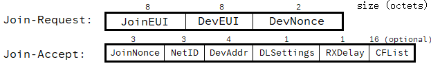
JoinNonce is a non-repeating value provided by the Join Server and used by the end-device to derive the two session keys NwkSKey and AppSKey, which shall be calculated as follows:
NwkSKey = aes128_encrypt(AppKey, 0x01 | JoinNonce | NetID | DevNonce | pad16)
AppSKey = aes128_encrypt(AppKey, 0x02 | JoinNonce | NetID | DevNonce | pad16)
The Join-Request frame is not encrypted. The Join-Accept frame itself shall be encrypted with the AppKey.
Gateways
Gateways receive LoRa modulated RF messages from end devices and forward them to the Network Server through an IP backbone.
- Operate on the physical layer as LoRa radio message forwarders
- Demodulate LoRa packets and forward them to the Network Server via internet or LAN
- Check the data integrity of each incoming LoRa RF message; if not intact (CRC is incorrect), the message will be dropped
- For LoRaWAN downlinks, a gateway executes transmission requests coming from the LNS without any interpretation of the payload
- A single eight-channel gateway can support a few hundred thousand messages over the course of a 24-hour period
- No fixed association between an end device and a specific gateway; uplink packet sent by the end device will be received by all gateways within reach. Deduplication is handled by the Network server.
Based on the Received Signal Strength Indicator (RSSI) levels of the identical messages, the network server typically selects the gateway that received the message with the best RSSI when transmitting a downlink message because that gateway is the one closest to the end device in question.
If two messages sent over the same frequency, arrive at the gateway simultaneously, one of them will get lost.
As full-duplex radios are not widely available yet, a gateway is not able to receive transmissions from devices while transmitting itself. This means that if a gateway is transmitting 10% of the time, it's not able to receive anything for that 10% of the time.
Gateways also include the following metadata into a message:
- Received Signal Strength Indicator (RSSI)
- Signal-to-Noise Ratio (SNR)
- Time-of-arrival (TOA)
- Frequency channel
- Data rate
LoRa packet forwarder
Program running on the host of a LoRa-based gateway that forwards RF packets received by the concentrator (uplinks) to a LoRaWAN Network Server and also transmits RF packets sent by the NS (downlinks) through a secured IP link.
Popular implementations are:
- Semtech UDP Packet Forwarder - the first packet forwarder, connecting to servers through the Semtech UDP protocol.
- Semtech Basics Station - new packet-forwarder based on WebSockets.
Network Server
The Network Server manages gateways, end-devices, applications, and users in the entire LoRaWAN network.
- Analog to a "router" of the LoRaWAN protocol
- Forwarding uplink application payloads to the appropriate application servers
- Queuing of downlink payloads coming from any Application Server to any device connected to the network
- Managing the downlink message queue and selecting a gateway to send a downlink through based on link quality (RSSI, SNR)
- Handles authentication and end-to-end security
- Validating the authenticity of end devices and integrity of messages
- Deduplicating uplink message
- Providing acknowledgments of confirmed uplink data messages
- Forwarding Join-request and Join-accept messages between the devices and the join server
- Adapting data rates using the ADR protocol
Application Server
The Application Server processes application-specific data messages received from end devices.
- Receives and decrypts data (uplinks) from the Network Server
- Encrypts data and sends them to the end-devices (downlink)
- Data events can be integrated with destinations like MQTT, HTTP, AWS SNS, PostgreSQL, etc.
Join Server
The Join Server assists in secure device activation, root key storage, and session key generation - generates keys for encrypting and signing messages.
Over the air activation (OTAA):
- End-device sends a Join-request message to the Join Server through the Network Server.
- The Join-server processes the Join-request message, generates session keys, and
- transfers NwkSKey (Network session key) and AppSKey (Application session key) to the Network server and the Application server respectively
Application Server has the role of the Join Server in many implementations (Chirpstack).
Profiles
Device Profile
Device Profile includes End-Device capabilities and boot parameters that are needed by the NS for setting up the LoRaWAN radio access service.
DeviceProfileID- ID of the Device ProfileSupportsClassB- end-device supports Class BSupportsClassC- end-device supports Class CMACVersion- version of the LoRaWAN supported by the end-deviceSupportsJoin- end-device supports Join (OTAA) or not (ABP)RFRegion- RF region name
Service Profile
Service Profile includes service parameters that are needed by the NS for setting up the LoRa radio access service and interfacing with the AS.
ServiceProfileID- ID of the Service ProfileULRate- uplink token bucket filling rate, including ACKs (packet/h)DLRate- downlink token bucket filling rate, including ACKs (packet/h)AddGWMetadata- GW metadata (RSSI, SNR, GW geoloc., etc.) are added to the packet sent to ASDevStatusReqFreq- frequency to initiate an End-Device status request (request/day)ReportDevStatusBattery- report end-device battery level to AS
Regional Parameters
| Plan | EU868 | US915 | AU915 | CN779 |
|---|---|---|---|---|
| Default Freq band MHz | 863 to 870 | 902 to 928 | 915 to 928 | 779 to 787 MHz |
| Man. Channel Freq MHz | 868.10, 868.30, 868.5 | up: 64, down: 8 | up: 64, down: 8 | 779.5, 779.7, 779.9 |
| JoinReq DataRate | [0:5] | [0:4] | [2:6] | [0:5] |
| CFList Type Support | 0 | 1 | 1 | 0 |
| Man. Data Rate | [0:5] | [0:4], [8:13] | [0:6], [8:13] | [0:5] |
| Opt. Data Rate | [6:7] or [6:11] | [5:6] | [7] | [6:7] |
| Number of channels | 16 | up: 64+8, down: 8 | up: 64+8, down: 8 | 16 |
| Default channels | [0:2] | [0:71] | [0:71] | [0:2] |
| Default RX1DRoffset | 0 | 0 | 0 | 0 |
| Allowed RX1DRoffset | [0:5] | [0:3] | [0:5] | [0:5] |
| Duty Cycle | < 1% | No limit | No limit | < 1% |
| Dwell time limit | No | [0:63] 400ms, [64:71] No | [0:63] 400ms, [64:71] No | No |
| TxParamSetupReq | No | No | Yes | No |
| Max EIRP - TXPower 0 | +16 dBm | +30 dBm | +30 dBm | +12 dBm |
| Default RX2DataRate | DR0 | DR8 | DR8 | DR0 |
| Default RX2 Freq | 869.525 MHz | 923.3 MHz | 923.3 MHz | 786.0 MHz |
Default settings (recommended)
| Attribute | Value |
|---|---|
| RECEIVE_DELAY1 | 1s |
| RECEIVE_DELAY2 | 2s (RECEIVE_DELAY1 + 1s) |
| RX1DROffset | 0 (table index) |
| JOIN_ACCEPT_DELAY1 | 5s |
| JOIN_ACCEPT_DELAY2 | 6s |
| MAX_FCNT_GAP | 16384 |
| ADR_ACK_LIMIT | 64 |
| ADR_ACK_DELAY | 32 |
| RETRANSMIT_TIMEOUT | 2s +/- 1s |
EU868 (EU863-870 MHz Band)
- Bandwidth: 125 kHz
- Channel Frequency: 868.10, 868.30, 868.50 MHz (mandatory) + 13 optional = 16 possible channels
- DR / Bitrate: DR0 to DR5 / 0.3-5 kbps
- Nb Channels: 3
- Duty cycle: < 1%
| Data Rate | DRNext | Configuration | Bit-rate | Max MACPayload size |
|---|---|---|---|---|
| 0 | NA | SF12 / 125 kHz | 250 bit/s | 59 |
| 1 | 0 | SF11 / 125 kHz | 440 bit/s | 59 |
| 2 | 1 | SF10 / 125 kHz | 980 bit/s | 59 |
| 3 | 2 | SF9 / 125 kHz | 1760 bit/s | 123 |
| 4 | 3 | SF8 / 125 kHz | 3125 bit/s | 230 |
| 5 | 4 | SF7 / 125 kHz | 5470 bit/s | 230 |
| 6 | 5 | SF7 / 250 kHz | 11000 bit/s | 230 |
| 7 | 6 | FSK: 50 kbps | 50000 bit/s | 230 |
| 8 | 0 | LR-FHSS CR1/3 137 kHz | 162 bit/s | 58 |
| 9 | 8 | LR-FHSS CR2/3 137 kHz | 325 bit/s | 123 |
| 10 | 0 | LR-FHSS CR1/3 336 kHz | 162 bit/s | 58 |
| 11 | 10 | LR-FHSS CR2/3 336 kHz | 325 bit/s | 123 |
| 12..14 | RFU |
US915 (US902-928 MHz ISM Band)
- Bandwidth: 125 kHz and 500 kHz
- Channel Frequency:
- Upstream: 64 channels (0-63) 902.3 MHz to 914.9 MHz (by 200 kHz) for 125 kHz bandwidth
- Upstream: 8 channels (64-71) 903.0 MHz to 914.2 MHz (by 1.6 MHz) for 500 kHz bandwidth
- Downstream: 8 channels (0-7) 923.3 MHz to 927.5 MHz (by 600 kHz) for 500 kHz bandwidth
- DR / Bitrate:
- Upstream: DR0 to DR5 / 0.3-3.1 kbp for 125 kHz bandwidth
- Upstream: DR4 or LR-541 FHSS DR5-DR6 for 500 kHz bandwidth
- Duty cycle: no limit
| Data Rate | DRNext | Configuration | Bit-rate | Max MACPayload size |
|---|---|---|---|---|
| 0 | NA | SF10 / 125 kHz | 250 bit/s | 19 |
| 1 | 0 | SF9 / 125 kHz | 440 bit/s | 61 |
| 2 | 1 | SF8 / 125 kHz | 980 bit/s | 133 |
| 3 | 2 | SF7 / 125 kHz | 1760 bit/s | 230 |
| 4 | 3 | SF8 / 125 kHz | 3125 bit/s | 230 |
| 5 | 0 | LR-FHSS | 162 bit/s | 58 |
| 6 | 5 | LR-FHSS | 325 bit/s | 133 |
| 7 | RFU | |||
| 8 | SF12 / 500 kHz | 980 bit/s | 53 | |
| 9 | SF11 / 500 kHz | 1760 bit/s | 129 | |
| 10 | SF10 / 500 kHz | 3900 bit/s | 222 | |
| 11 | SF9 / 500 kHz | 7000 bit/s | 222 | |
| 12 | SF8 / 500 kHz | 12500 bit/s | 222 | |
| 13 | SF7 / 500 kHz | 21900 bit/s | 222 |
AU915 (AU915-928 MHz Band)
- Bandwidth: 125 kHz and 500 kHz
- Channel Frequency:
- Upstream: 64 channels (0-63) 915.2 MHz to 927.8 MHz (by 200 kHz) for 125 kHz bandwidth
- Upstream: 8 channels (64-71) 915.9 MHz to 927.1 MHz (by 1.6 MHz) for 500 kHz bandwidth
- Downstream: 8 channels (0-7) 923.3 MHz to 927.5 MHz (by 600 kHz) for 500 kHz bandwidth
- DR / Bitrate:
- Upstream: DR0 to DR5 / 0.3-3.1 kbp for 125 kHz bandwidth
- Upstream: DR6 or LR-541 FHSS DR7 for 500 kHz bandwidth
- Downstream: DR8 to DR13 for 500 kHz bandwidth
- Duty cycle: no limit
| Data Rate | DRNext | Configuration | Bit-rate | Max MACPayload size |
|---|---|---|---|---|
| 0 | NA | SF12 / 125 kHz | 250 bit/s | 59 |
| 1 | 0 | SF11 / 125 kHz | 440 bit/s | 59 |
| 2 | 1 | SF10 / 125 kHz | 980 bit/s | 59 |
| 3 | 2 | SF9 / 125 kHz | 1760 bit/s | 123 |
| 4 | 3 | SF8 / 125 kHz | 3125 bit/s | 230 |
| 5 | 3 | SF7 / 125 kHz | 5470 bit/s | 230 |
| 6 | 5 | SF8 / 500 kHz | 12500 bit/s | 230 |
| 7 | LR-FHSS | 162 bit/s | 58 | |
| 8 | SF12 / 500 kHz | 980 bit/s | 61 | |
| 9 | SF11 / 500 kHz | 1760 bit/s | 137 | |
| 10 | SF10 / 500 kHz | 3900 bit/s | 230 | |
| 11 | SF9 / 500 kHz | 7000 bit/s | 230 | |
| 12 | SF8 / 500 kHz | 12500 bit/s | 230 | |
| 13 | SF7 / 500 kHz | 21900 bit/s | 230 |
CN779 (CN779-787 MHz Band)
- Bandwidth: 125 kHz
- Channel Frequency: 779.5, 779.7, 779.9 MHz
- DR / Bitrate: DR0 to DR5 / 0.3-5 kbps
- Nb Channels: 3
- Duty cycle: < 1%
| Data Rate | DRNext | Configuration | Bit-rate | Max MACPayload size |
|---|---|---|---|---|
| 0 | NA | SF12 / 125 kHz | 250 bit/s | 59 |
| 1 | 0 | SF11 / 125 kHz | 440 bit/s | 59 |
| 2 | 1 | SF10 / 125 kHz | 980 bit/s | 59 |
| 3 | 2 | SF9 / 125 kHz | 1760 bit/s | 123 |
| 4 | 3 | SF8 / 125 kHz | 3125 bit/s | 230 |
| 5 | 4 | SF7 / 125 kHz | 5470 bit/s | 230 |
| 6 | 5 | SF7 / 250 kHz | 11000 bit/s | 230 |
| 7 | 6 | FSK: 50 kbps | 50000 bit/s | 230 |
| 8..14 | RFU |
ChirpStack LoRaWAN
ChirpStack provides open-source components for LoRaWAN networks.
- Gateway Bridge: handles the communication between the LoRaWAN gateways and the Network Server
- Chirpstack: LoRaWAN Network Server, Application Server and Join Server implementation
- Gateway OS: Linux-based OS to run the (full) ChirpStack stack on a Raspberry Pi-based LoRa gateway
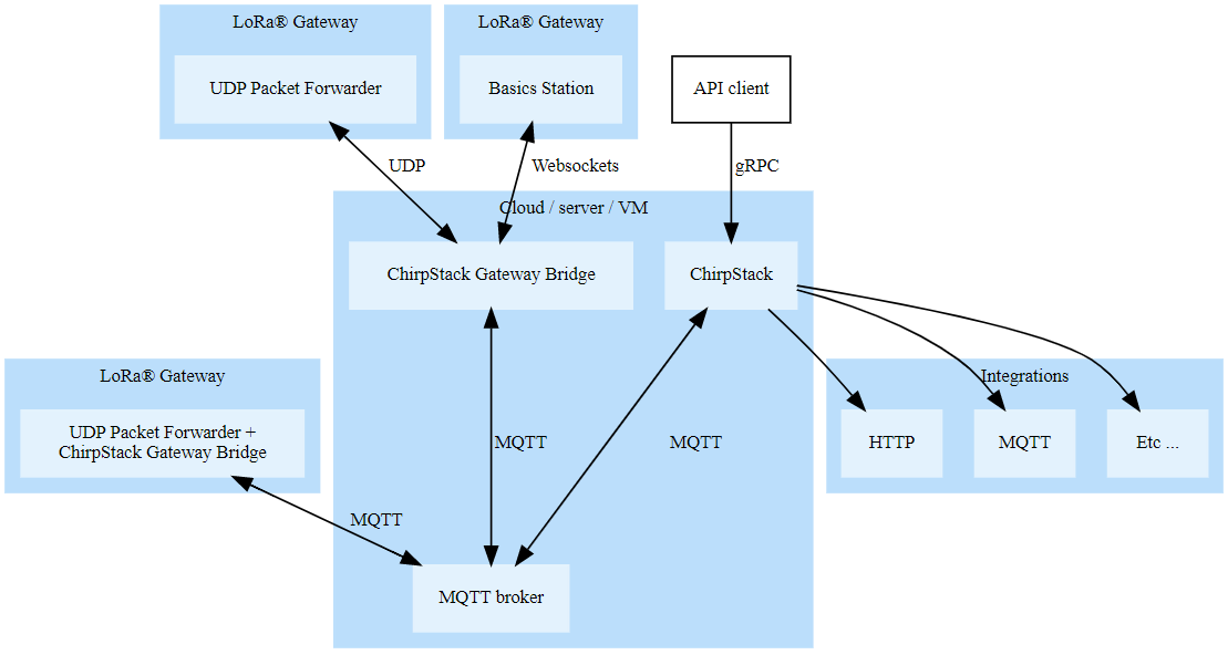
ChirpStack Gateway Bridge
Converts LoRa® Packet Forwarder protocol into a ChirpStack common data format.
The following Packet Forwarder backends are provided:
Integration with the Chirpstack (NS) is provided via MQTT.
LoRa packet PHYPayload ==lora==> Packet Forwarder protocol ==udp==> Chirpstack format ==mqtt==> Chirpstack (NS)