Introduction to Pandora - tsirif/pandora-playground GitHub Wiki
Pandora Topics
###1. Introduction to Pandora
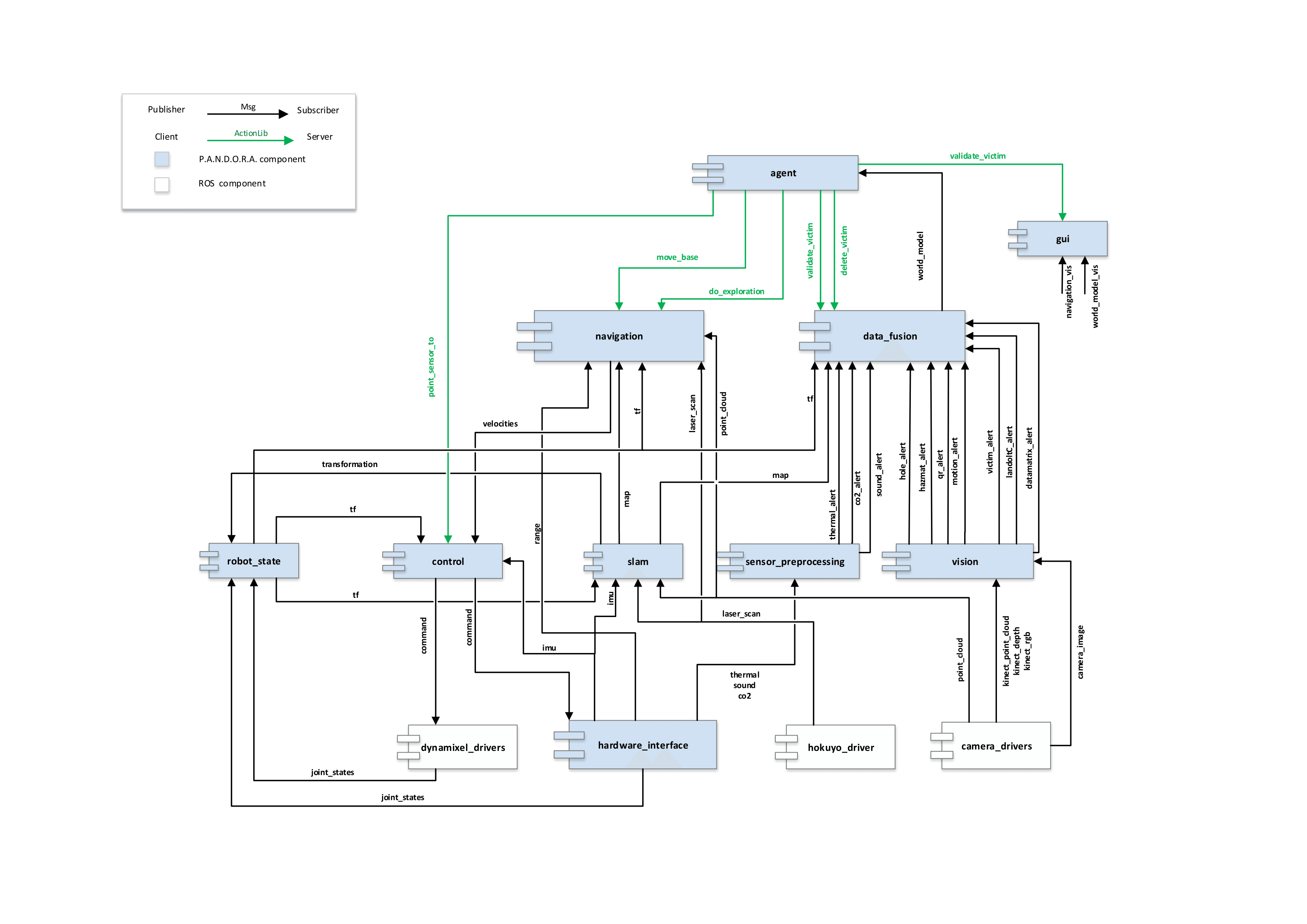
Welcome to PANDORA! In this section we will describe PANDORA's software system as a whole. The image above (right-click then view-image to see in full resolution) depicts the 2013-2015 component diagram of PANDORA. As you can first notice, components form parallel lines in the diagram. The diagram uses this to reveal that the system architecture is organized in layers. Each layer contains components that manage information of the same level. Higher-layer components handle higher-level information. How high an information is labeled depends on how much this information was processed previously, how was this information obtained and how well it is organized in patterns (objects in OOP). I will begin describing the diagram layer to layer from bottom to top.
Layer 0
This component layer contains all software that wraps raw information (incoming/outgoing) to ROS messages in order to pass this information to our system that communicates using ROS. These components are labeled as the lowest level because they are converting raw information gained by the robot's sensors. In reality they are the highest level drivers of robot's sensors and actuators, leading information from computer's operating system to ROS and thus our software. The lower level drivers are programs used in microprocessors (AVR, ARM etc) and programs that handle computer's i/o ports and buses. More information about drivers and layer 0 software in general you will find in PANDORA's hardware wiki.
Components:
- dynamixel_drivers: Piece of software that converts ros messages defined by this package to appropriate information which is sent to dynamixels in order to move. This was not written by PANDORA team.
- hardware_interface: This component contains drivers for PANDORA's parts which had not appropriate ROS-compliant software and thus was needed to be written from scratch. Such piece of hardware are microprocessors programmed to serve something specific for PANDORA's needs: interface of XMEGA (sonars and batteries) and ARM (thermal info, microphones and co2 sensor) microprocessors and drivers for Pololu linear actuator, IMU and controllers of motors.
- hokuyo-driver: Driver that converts information from Hokuyo lazer.
- camera-drivers: Drivers that convert information from usb cameras, kinect or xtion.
Layer 1
This component layer contains software that handles raw information in order to produce higher-level information (which is based on patterns) or software that handles higher level orders and converts them to raw information which are actually commands that an actuator understands. Also, there exists a module which calculates and publishes tfs for every joint in our robot model.
Components:
- vision: The vision component recognises visual patterns and calculates their direction from the eye of the camera in relation with the camera frame (projective camera model). Vision's modules are hole (which recognises holes which appear throughout the robocup rescue stage), victim/face (which recognises the dolls which are used in the robocup rescue mission), hazmat (which recognises signs indicating dangerous material), qr, landolt-c, data-matrix and motion (which exists sometimes along with a doll which simulates an alive victim). Each module takes as input usb and kinect camera frames and outputs an alert message, which contains pattern and directional info (yaw and pitch relative to camera's tf).
- sensor processing: Contains modules for thermal, co2 and sound recognition.
- slam: The slam component has algorithms that solve the Simulateneous Localization And Mapping problem. Contains modules for 2d/3d mapping and pose estimation. Takes as input the depth information from kinect and the raw distances measured by lazer sensor. Outputs the transformation of the robot frame to the world map frame.
- control: Has modules which try to interpret a higher level order into right commands which the actuators will hear. Uses tf in order to dynamically fix the commands given to the actuators.
- robot state: Uses transformation published by slam and the joint states published by the actuators' drivers in order to recreate robot's model using tfs.
Layer 2
This layer has navigation and data fusion components, as well as a module which calculates and publishes sensors' coverage.
Components:
- navigation: Uses map, tf and raw localization and mapping information in order to find and execute the right path to a selected goal in space. Currently, it also supports deciding the next goal the robot should have if it where to explore the world. It has the following modules: costmap (which calculates traversability of the world according to measurements and builds a world model from navigation's point of view), global planner (calculates the best path towards a goal using info from the costmaps), local planner (tries to execute as closely as possible the global path by dynamically choosing the trajectory which best follows locally the global path) and explorer (tries to find next navigation goal when we are exploring the world). Generally the component takes an order from agent to move somewhere/somehow as input and sends motor velocities in real time to the control component.
- data fusion: This component handles all alerts that are produced by the 'sensor processing' and 'vision' components of layer 1, along with the map produced by 'slam' and robot's tfs published by 'robot state', and tries to build a model of the world, abstract but descriptive enough for an "intelligent" agent to play on. It also estimates the poses of the points of interest to the world map frame and fuses probabilities on victim verification, keeping thus the business logic of the robocup rescue problem.
- sensor coverage: Future: This component/module will trace sensors' movement and range in order to understand how much of the explored world is actually covered by a type of sensor that concerns victim identification.
Layer 3
The topmost layer in Pandora's 2013-2015 system architecture consists of an agent and a finite state machine. The agent plays on the playboard, which data fusion produces, listening to messages describing the world model and chooses to change from a current state in strategy to another, based on this information. Roughly speaking, it decides the way that the robot will behave: Will it explore? Will it move to a point of interest? Has a candidate victim been found? Can we verify the existence of a victim? According each state, agent orders navigation to move the robot, exploration to explore efficiently, 'gui' to validate a victim and data fusion to alter the world model.
Besides layers
Finally, there are three more modules in Pandora's software that cannot belong to any layer as described in this architecture:
- GUI: The first one is the GUI module, which is a graphical interface among the user of the robot and the agent. It gives the user details about robot's perception, hardware state and measurements, robot's state of operation and details about the victim to be verified. Also, gives the ability to the user to select the level of autonomy of the robot (full autonomous, autonomous navigation or teleoperation). It is written in python and rqt. Finally this module is not executed on the robot, but on user's remote - yet connected - machine.
- Geotiff: This one makes an image of the world model, the map, the robot and sensor's coverage (and others by demand) upon request. It asks data fusion module to deliver all sufficient details. It runs on user's machine as well.
- State Server: This module runs on the robot and its function is to keep track of the robot's state of operation and announce any change in state to whoever inherits from StateClient.