HSYNC | LPC1768 double edged PWM control - tarasjg/mbed-vga GitHub Wiki
HSYNC
The horizontal sync signal was generated using a double edge controlled PWM output. This is not supported natively by mbed OS, so it was necessary to configure directly at the register level. Consider the following diagram to understand double edge control:
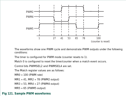
The PWM peripheral features a Timer Counter (TC) register at its heart. Match registers are configured that can either manipulate the timer counter or the PWM output. Match Register 0, or MR0, is used in this case as the TC reset register. Before any of these registers are configured though, the PCLK of the PWM peripheral is set to CCLK (100MHz). The prescaler (PR) defines when the TC increments. More formally, the TC is incremented ever PR+1 cycles of PCLK. Thus, PR is set to 3, yielding an increment frequency of the TC of 25MHz. Since one clock is equivalent to one pixel, we can think of the TC as incrementing for every pixel displayed.
This makes things relatively simple. MR0 is set to 800. This is the amount of pixels (visible and in the blanking area) for each line. This makes the PWM timer reset every line. Next MR2 and MR1 are set at the respective times that HSYNC drops low in the line. Note that we trigger on MR2 and then MR1 since HSYNC is active low. The following init and enable routines are defined below:
void init_hsync() {
    //LPC_SC -> PCONP = 0;
    //power on pwm
    LPC_SC -> PCONP |= (1<<6);
    //set pwm periph clock
    LPC_SC -> PCLKSEL0 |= (1<<12);
    //pin select (PWM1.2 on P2.1 -> DIP25)
    //LPC_PINCON -> PINMODE_OD2 |= (1<<1);
    LPC_PINCON -> PINSEL4 |= (1<<2);
    //disable internal pull down and pull up resistors
    LPC_PINCON -> PINMODE4 |= (1<<3);
    //set prescale to make 25Mhz timer count (TC)
    LPC_PWM1 -> PR = 3;
    //set trig for PWM TC to reset after each line
    LPC_PWM1 -> MR0 = 800;
    //enable TC reset on MR0 match (end of line)
    LPC_PWM1 -> MCR = 1<<1;
    //set trig for HSYNC to go low after 656 pixels
    LPC_PWM1 -> MR2 = 656;
    //set trig for HSYNC to go high after 752 pixels
    LPC_PWM1 -> MR1 |= 752;
    //enable double edged control on MR2/MR1 trigs
    LPC_PWM1 -> PCR = 1<<2;
    //enable output
    LPC_PWM1 -> PCR |= 1<<10;
}

void hsync_enable() {
    //enable TC
    LPC_PWM1 -> TCR |= 1;
    //enable PWM
    LPC_PWM1 -> TCR |= 8;
}
This routine was validated with an Agilent 54622D:
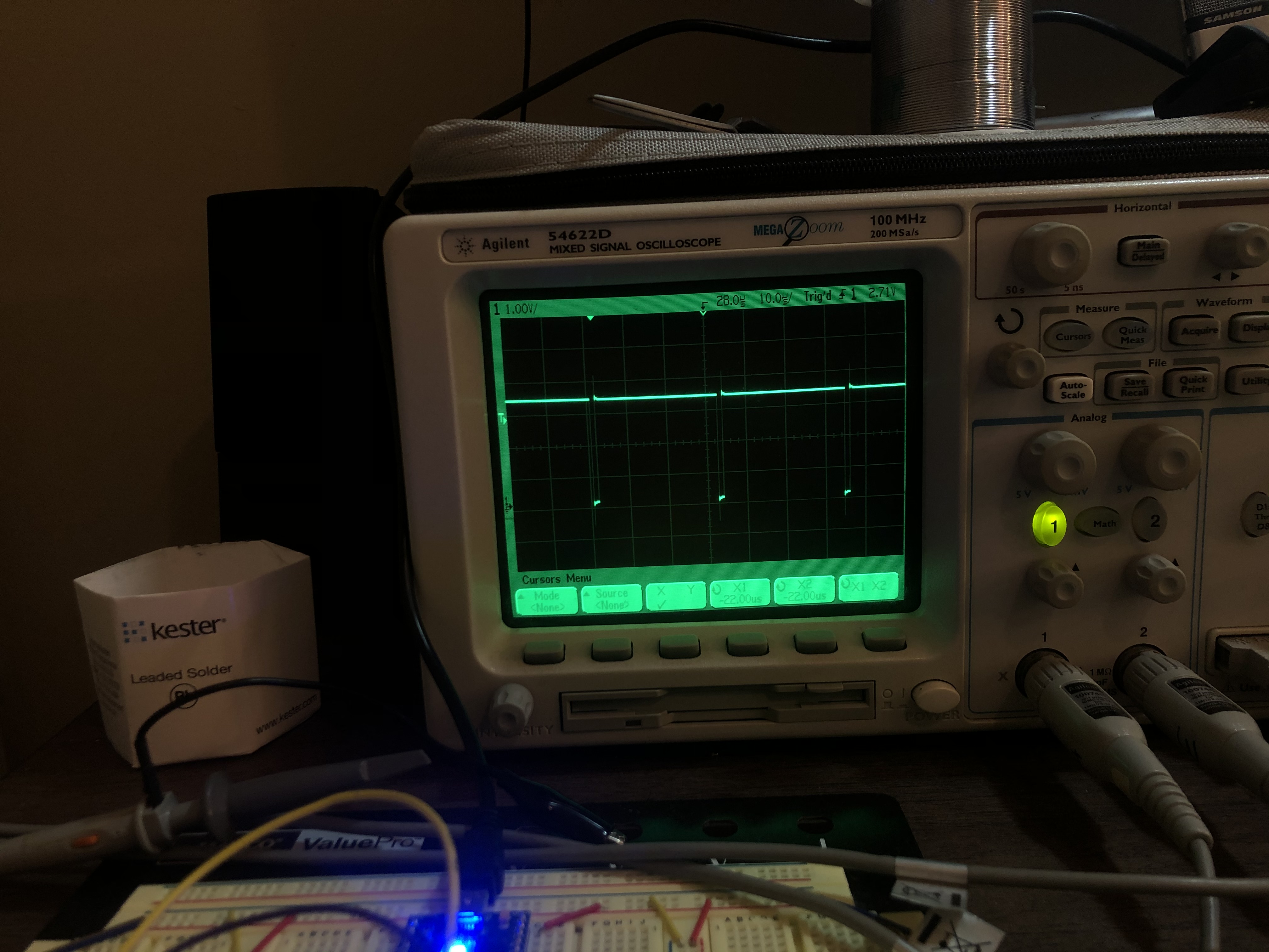
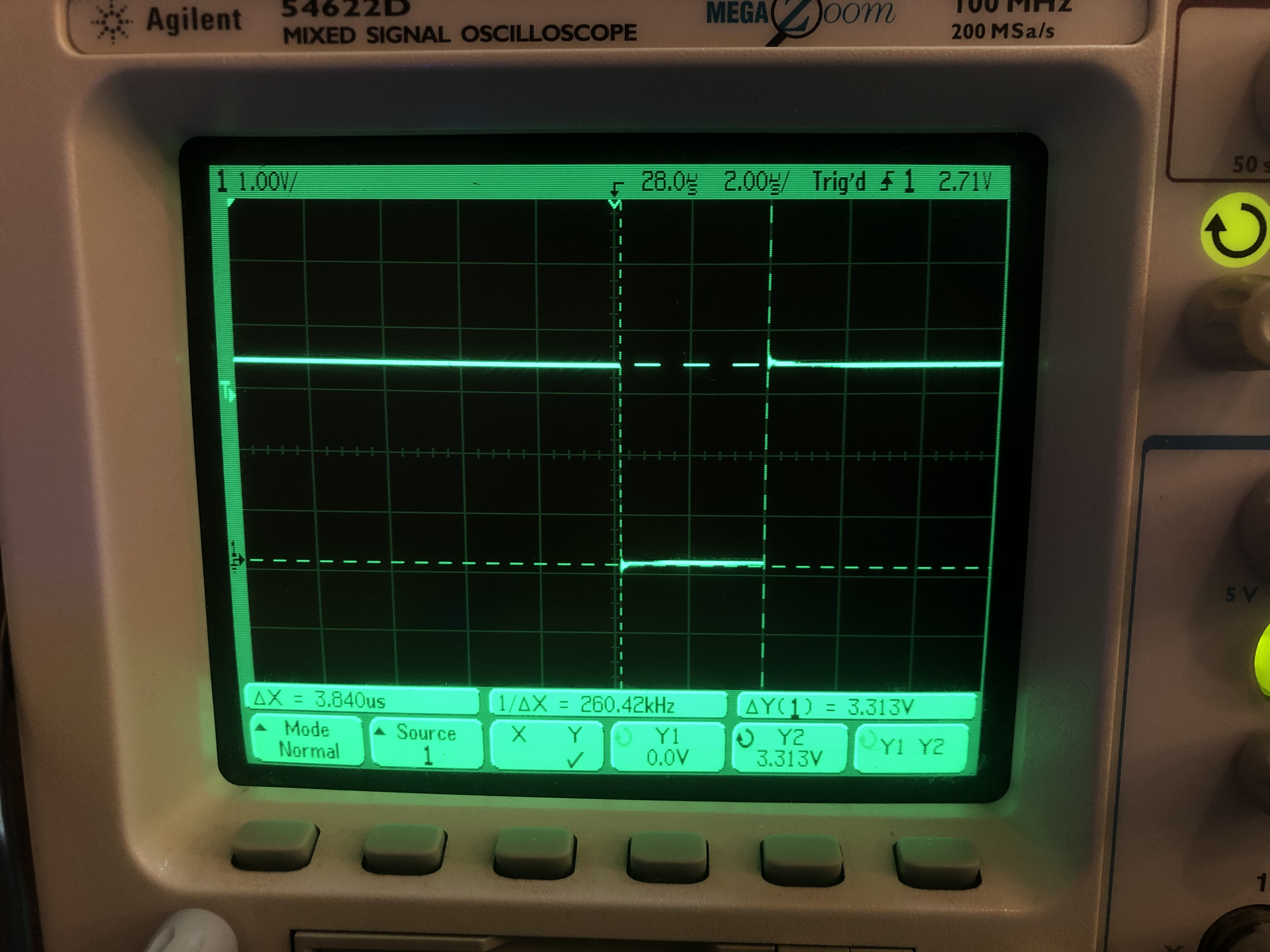
The low time (pictured) as well as the front, back, and overall line time was measured and verified to be very close to the VGA specification.