Mechanical Assembly - tangentaudio/opencv_tank_gauge GitHub Wiki

Requirements
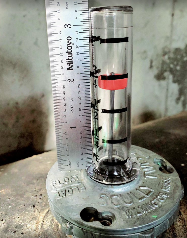
The mechanical design of this project is only suitable (without modification) for a Scully Twis-Lok oil tank gauge.
There are many types of gauges and vials in the wild. The concepts and software of this project could easily be applied to other models, but it's beyond the scope of this project to support every type.
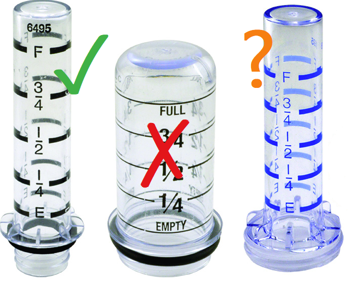
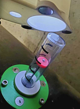
Start by inspecting your gauge vial. If it's short and stubby like the middle image, this design definitely won't work without major changes. It's designed to work with the style on the left, and it may work with the style on the right, but might require a modified base plate design. If in doubt, 3D print the Base Mount part first - a quick and easy print. Test this for fitment before proceeding.
Vial Modification
Slight modification of the clear plastic vial helps improve the computer vision process dramatically. By removing half of the painted markings with isopropyl alcohol and a rag, it removes markings that might "confuse" the computer vision algorithm. If you're uncomfortable modifying your current vial, you can get a replacement gauge vial online or from your oil supplier. My old vial was cracked from prior over-tightening, so it was worth replacing as part of this project.
It's best to fully assemble the project before you modify your vial, as the exact positioning of the vial and 3D printed parts will vary from installation to installation. By assembling everything first, you can easily tape off the side of the vial that faces the camera, and remove the markings on the opposite side. I removed markings on two vials fairly easily with some 90% isopropyl, a paper towel, and a little bit of patience. The black paint used is not very tenacious and came off easily, especially on the newer replacement vial I bought online.
Bill of Materials
- Matte White PLA filament
- Alternate color PLA filament (optional, any color - I used dark gray)
- PETG filament (optional, any color - I used green)
- (Qty 2) M2 x 8mm screws
- (Qty 2) M2 nuts
- (Qty 6) M2.5 x 6mm screws
- (Qty 2) M2.5 washers
- (Qty 2) M2.5 x 4mm x 3.8mm brass insert nuts
- (Qty 3) 10-24 x 1/2" socket head cap screws
- (Qty 6) 12mm x 2mm rare earth magnets
- PTFE protective tape, 1/2" wide or similar (electrical tape OK)
- Thin EVA foam or similar
- Cyanoacrylate adhesive (aka super glue)
- Hot glue (optional)
Tools
- 3D Printer
- X-Acto style knife for cutting foam and parts cleanup
- Sandpaper or emery board for parts fitting and cleanup
- Screwdrivers and hex drivers
- Needle nose pliers
- Heat gun (for hot-insert brass nuts)
3D Printed Parts
The custom enclosure requires many hours of 3D printing, but all parts have been designed to be easy to print with minimal or no supports. A single color PLA filament should work fine for printing the entire design, but I chose to print a couple of parts in PETG for durability, and an alternate color PLA for the cover part, for aesthetic reasons.
Detail is not particularly critical for any of these parts, so I chose to print them all in 0.30mm DRAFT mode on my Prusa Mk3. The only part that needs supports is the camera mount. Other parts should print fine without supports if oriented as shown in the images.
The STL files are located in the Git repository under the mechanical/ directory.
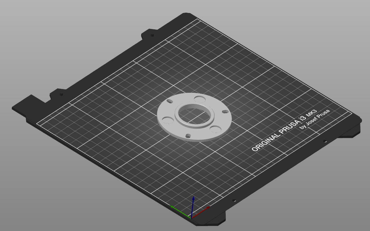
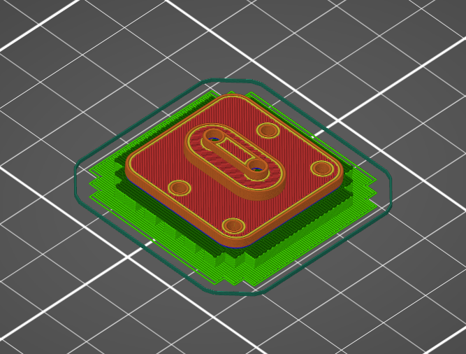
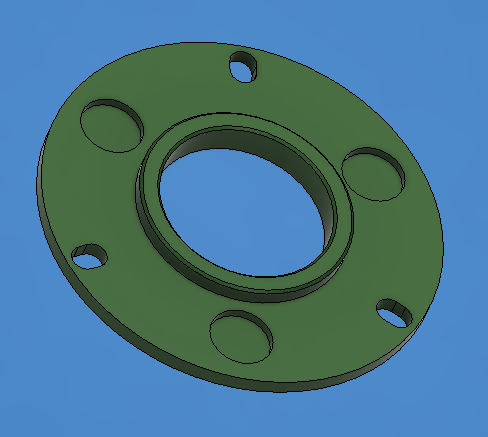
Base Mount - BaseMount.stl
This part is printed in PETG for flexibility, since it is bolted to the oil tank gauge and may see some minor flexing. You can probably get away with printing it in PLA if you're careful when you attach it to the tank gauge.
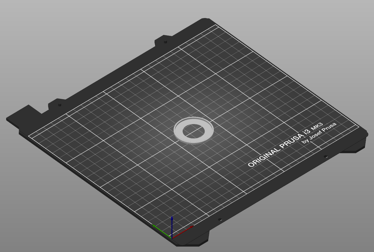
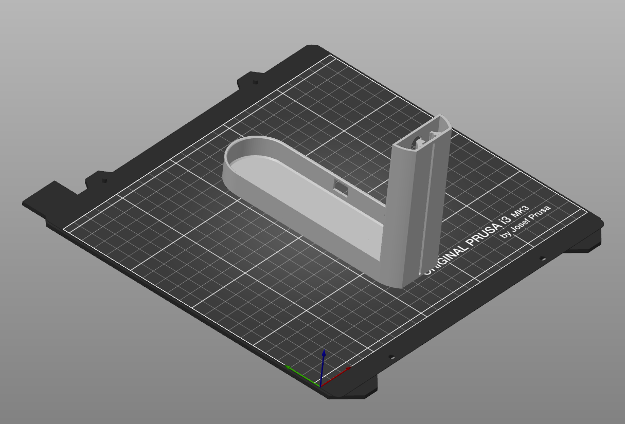
Base Cover - BaseCover.stl
This is a simple part printed in matte white PLA, which slides over the gauge vial to cover up the vial base, once the base mount has been installed.
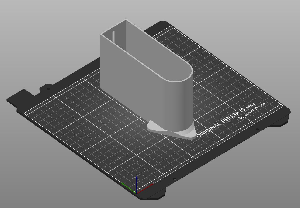
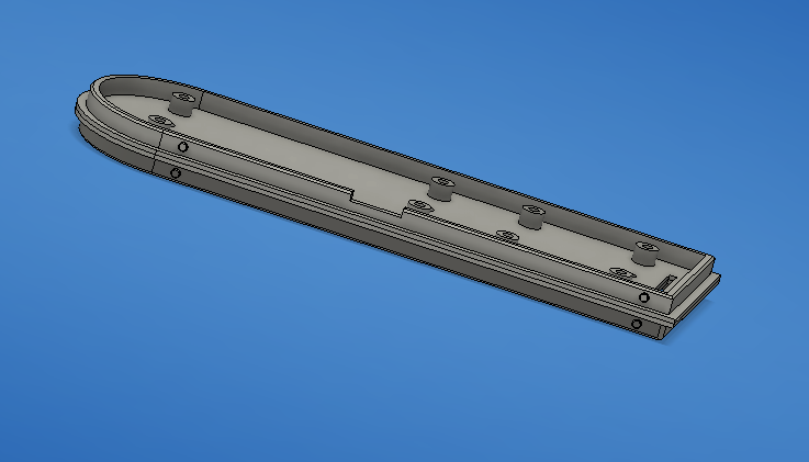
Wall Structure - WallStructure.stl
This is the largest print for the project, but it's a fairly forgiving one. This part should be printed in matte white PLA. If you can't source matte white PLA, print it in another color of PLA and paint the inside with flat white paint suitable for plastics. Don't print it in PETG if you need to paint it, as the paint will not stick. The interior color of this part is critical because it helps reflect and diffuse the camera lighting.
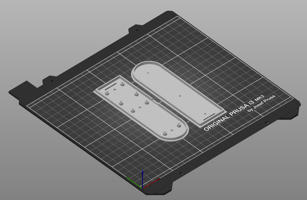
Lower Lid (LidLower.stl) and Mid Lid (LidMid.stl)
These two parts should be printed in the same white PLA as the wall structure above. The inside of the lower lid should be painted flat white if you must use a different color.
Top Lid - LidTop.stl
This is another large part, but it's also an easy print. I chose to print this in a dark gray PLA for my prototype because it looks cool, but almost anything will work.
Camera Mount - CameraMount.stl
This part is the only one that needs supports, as there are protruding features on the two broad sides of the part. I chose to print this part in PETG, but PLA should work fine if you're careful with assembly.
Assembly
Glue Lower- and Mid- Lid Pieces
Start assembly by gluing the lower and mid lid pieces together. Clean up surfaces after 3D printing and check the fitment. The proper alignment is flange-to-flange as shown in the image above. Spread a thin layer of cyanoacrylate adhesive on one piece, and carefully press the two together, being careful to align them properly, and most importantly, to not glue your fingers together with any glue that squeezes out.. All edges, the slot, and holes must line up. Clamp the parts together and set aside for the adhesive to cure.
If you choose, you can also take advantage of the three holes along the center line, which are sized to take a M2.5 screw. These can be used for temporary clamping or stay in place.
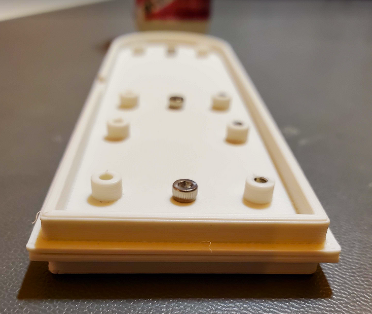
Install Magnets
Both the Base Mount and the Wall Structure are designed to accept magnets. The magnets must be installed carefully, observing proper N and S pole orientation between the two parts - ensuring they attract and don't repel each other! I found it easiest to use a magic marker to mark the poles of my magnets, and also to "test" them frequently by allowing them to stick together before adhering.
Depending on the accuracy of your 3D printer, you may find the magnets press fit and stay put, or you may find that you need to glue them. You may also find that you need to carefully enlarge the holes slightly so the magnets fit.
You can use cyanoacrylate glue to secure the magnets to PLA. A small dab of hot glue is likely a better choice for PETG. It's critical for the magnets to sit flat in the holes, so take your time with this.
Cut Gasket
The Scully gauge body is a metal casting that has some raised lettering, and a slight angle to it. To help account for the variability in this surface, I used a thin piece of EVA foam sandwiched in between the base mount and the top of the gauge body.
You likely have some existing packaging material around your house/lab that would work well for this purpose. Even a piece of cardboard would work reasonably well. Using an X-Acto knife and the base mount as a template, cut the foam material to the same footprint as the base mount.
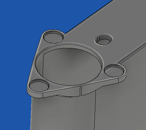
Install Base Plate and Base Cover
Remove the three screws from the Scully gauge, and slide the gasket and base mount over the top of the gauge. Replace the screws with three #10-24 1/2" SHCS. Don't over-torque these so much that you deform the base mount.
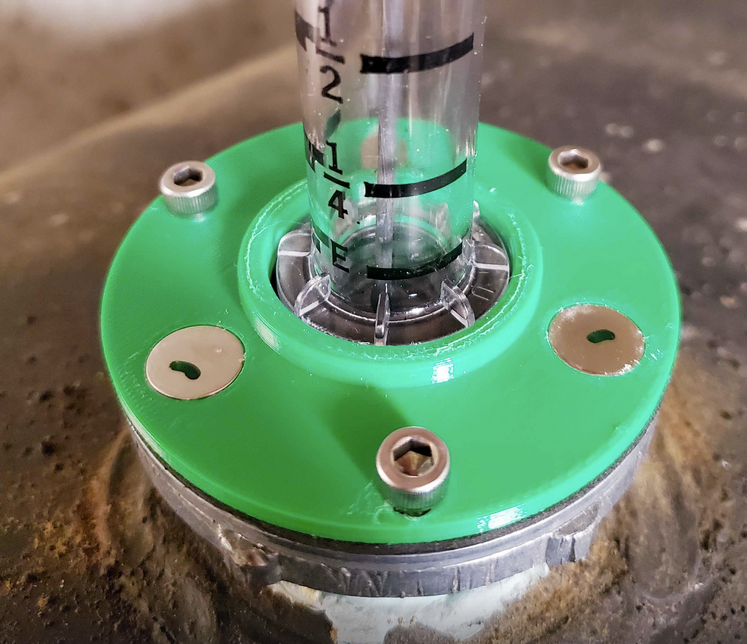
Once the Base Mount is installed, slide the Base Cover over the gauge vial. The ridges should point down. You can then test-fit the magnet mounting of the Wall Structure, and choose your preferred orientation. Choose a direction that keeps the curved wall pointed away from where you wish to view the LED level indicator.
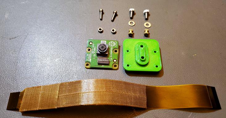
Camera Assembly
Collect all of the required parts for the camera assembly. You should have:
- 3D printed camera mount
- Official Pi Camera v2.x
- Pi Zero Flat Flex Cable (6 inch)
- (Qty 2) M2.5 x 4mm L x 3.8mm dia brass inserts
- (Qty 2) x 6mm L socket head cap screws
- (Qty 2) M2.5 washers
- (Qty 2) M2 x 8mm L socket head cap screws
- (Qty 2) M2 nuts
- Long M2.5 screw for heating inserts
- PTFE (or similar) tape
Thread an insert onto the long M2.5 screw, hold it with needle nose pliers, and heat it with a heat gun.
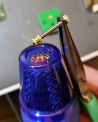
When hot, gently insert it into the appropriate hole on the camera mount print.
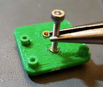
Repeat this for the other insert.
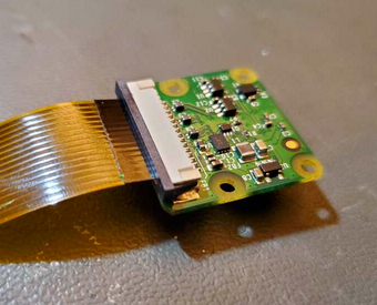
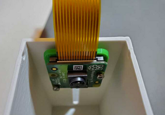
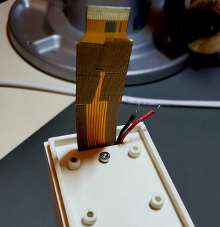
Because the camera flex cable runs through a slot and will sit under the DC-DC converter board, I chose to cover a section of it with a layer of PTFE fabric tape. You can also use electrical tape for this purpose. Once taped, insert the flat flex camera cable into the camera and close the locks. If you're uncomfortable with working with flex cables and connectors, some Googling should help you out.
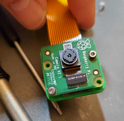
Mount the camera module to the mount using the two M2 screws and nuts. You can pick any two opposite corners for the screws.
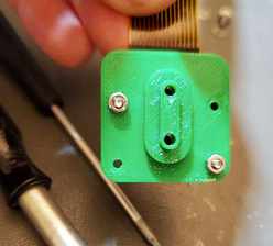
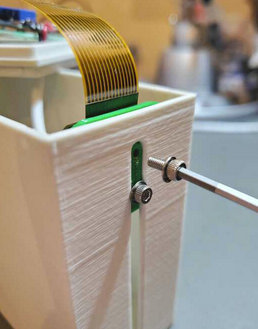
Lastly, mount the camera assembly in the slot on the rear of the main enclosure body. The boss on the rear of the camera assembly should fit cleanly in the slot on the enclosure body and slide up and down with minimal resistance. If there is resistance, you might want to do some light sanding inside of the slot.
Using the two M2.5 screws and washers, secure the camera assembly to the enclosure body. Keep the camera near the top for now, and don't tighten the screws too strongly. This will give you access to the lens to adjust the focus so it can clearly "see" the tank gauge. The final position is much lower in the enclosure, and will also be set in a later step.
Vision Lighting
There are no specific alignment or mounting points for the COB LED modules in the design so you can experiment with the exact location and method of lighting for computer vision processing. The simple approach of mounting the COB LEDs to the floor of the enclosure works well enough and it's easy, but it's far from ideal from a CV perspective. A more advanced approach might be to construct a basic coaxial illuminator using a piece of 50% mirror glass. Additionally, better diffusion of the COB LEDs might help improve image quality. A future update to the project may introduce improved lighting.
Prepare the wiring, heat-shrink and resistor modification of the COB LED modules, and then you are ready to mount them in the bottom of the main enclosure body. You might consider using something like Blue-Tak or some form of lighter double-sided adhesive before you commit to the stronger adhesive that is included on the back of the COB modules.
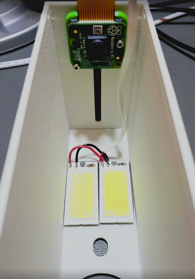
The exact positioning of the wiring is not critical, as long as it is not in the way of the camera lens or casting shadows. The wire will pass through the same slot that the camera cable passes.
Cables and Boards
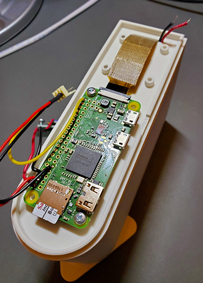
After you have spent some time on focusing and tuning the camera, you're ready to put the system together completely. Pass the cables through the slot in the lower lid sections as shown.
Connect the loose end of the camera cable to the Raspberry Pi camera connector. Again, do some Googling if you're unsure how to deal with these flat flex style connectors. Once the camera cable is secure, mount the Pi to the bosses using two M2.5 screws as shown. Keep the camera cable low and push the slack inside the enclosure body.
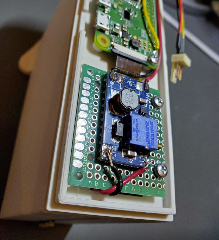
Lastly, mount the DC-DC converter board that you assembled earlier using two M2.5 screws. Solder the COB LED wiring to the output, and neatly route the 5V supply wiring back to the Pi.
NeoPixel Installation
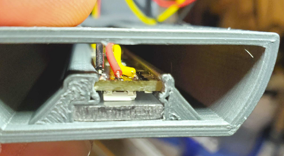
The RGB LED boards should be soldered end-to-end first, and the data/power wiring ready to go. Be certain they are well-aligned, as misalignment will cause them to bind up when installing. Make sure the data out end of the LED boards is the first to go into the slot. Carefully push the LED boards into the slot. There may be some resistance due to tight tolerances - you can try cleaning up the edges of the RGB boards a bit by sanding or scraping with a knife, but be careful. Before the boards are fully seated, feed the wiring through the hole near the top of the lid (the side with the "OpenCV" logo). Solder the wires onto the data input and power pins.
Once soldered and tested, you can push the LED boards the rest of the way into the slots and tidy up the wiring as below. Don't skip the testing, as this is likely your last chance to easily remove the boards without destroying the 3D print to get them out.
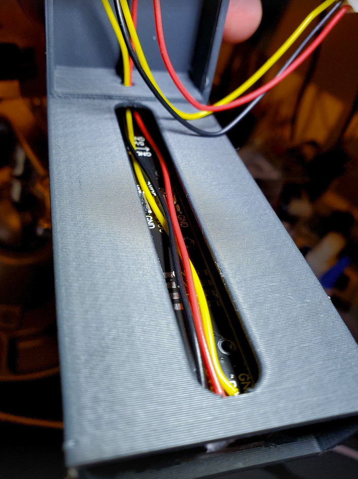
You can also install the optional diffuser at this time, by sliding it into the slot in front of the LEDs (as seen already installed, above).