Electronics Assembly - tangentaudio/opencv_tank_gauge GitHub Wiki
Bill of Material
You will need the following items. Note that many of the items are generic and available from many sources like eBay, AliExpress, Amazon, etc.
- Raspberry Pi Zero W - preferably without the header soldered on.
- Official Raspberry Pi Camera v2
- Pi Zero camera cable, 150mm length
- Quality micro USB Power Supply
- DC-DC adjustable boost converter (5V to 12V)
- (Qty 2) 40x20mm white 12V COB LED panel
- (Qty 2) NeoPixel sticks 8-RGB
- 0.1" Prototyping Perfboard - optional
- 3-pin header and plug - optional
- (Qty 2) Surface mount 0603 150 ohm resistors
- Misc small gauge wire in multiple colors, solder, heat shrink tubing, etc.
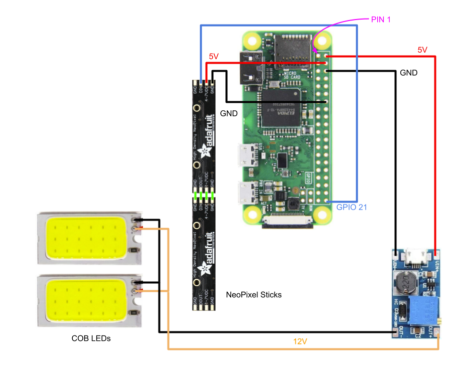
Wiring Diagram
Design Shortcuts
Strictly speaking, there are some shortcuts taken with this design that might cause some issues in some cases. The design has been tested by the author, but it may be pure luck that the specific components used worked in that case.
Power budget is the first potential issue. The goal was to run the entire system from the standard micro USB power input on the Pi Zero W. By powering the Pi, camera, the DC-DC converter and the RGB LED strip, it is possible for the components of the system to consume more current from the 5V power supply than it is capable of delivering. The most likely result will be a "sagging" 5V rail, which may result in unreliable operation or other 'strange' issues. It is also possible, though unlikely, that damage to the Pi or power supply could occur. Thus, it is highly recommended that you use a high quality micro USB supply - one rated for working with a Pi 3 for example. Don't just use any old 500mA USB wall wart that you have lying around.
Steps have been taken to limit the current consumption of the additional components, namely:
- The 12V COB LEDs are modified with higher value current limiting resistors to significantly reduce their consumption.
- The software drives the RGB LEDs at reduced output current levels, and avoids lighting all LEDs in white (the max output case).
Another shortcut is skipping the 3V/5V logic level conversion for the pin that drives the RGB LEDs. This was done for simplicity of wiring and assembly (aka laziness). For many types of RGB LEDs, this will work fine. However, if you're not seeing any output on the LEDs, it's possible this is the cause. Some Googling should help you find a solution that will help.
Lastly, a design improvement would be to provide a means of switching the vision LEDs on and off. There's no real benefit to continually performing measurements on the tank, as oil consumption is a relatively slow process. Being able to shut off the COB LEDs and ceasing image processing for periods of time would be a significant future improvement.
Modify and wire the COB LEDs
The COB LED modules have surface-mount current limiting resistors on them. As shipped, mine were 15 ohm, making the panels blindingly bright and very power hungry. Remove the stock resistors and replace with 150 ohm to significantly reduce brightness and current draw.
Desolder the existing power leads from the COB modules. Cut four lengths of red and black wire - approx 1 inch and 6 inches. Strip all ends about 1/4 inch. Twist the long and short red leads together and solder. Repeat the same for the black. Tin the remaining ends of the wires. Solder the short leads to one COB module, and the twisted junction to the other. Ensure you connect the red wires to the POSITIVE(+) and the black to the NEGATIVE(-). Apply a short length of heat shrink tubing to the long wires and shrink it close to the COB modules.
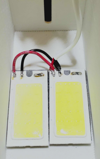
Use a bench power supply or other means to test the pair of COB modules by applying 12V to the new wiring and ensure both light up as expected.
Mount the DC-DC converter module
This is an optional step, but it helps tidy up the electronics. If you choose not to mount the converter, consider sleeving it with a piece of large heat shrink tubing instead.
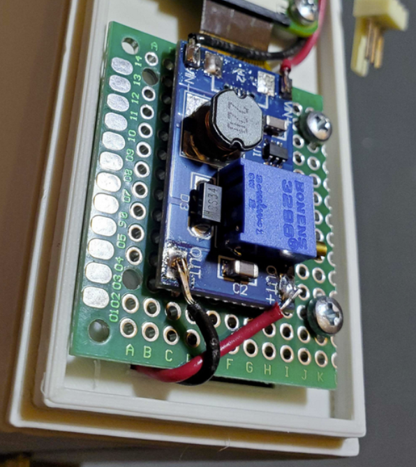
Cut a small piece of prototyping perfboard and solder the input and output pins of the DC-DC converter module through the board using stripped wire or cut component legs. They won't line up with the 0.1" holes in the perfboard, but you can get pretty close by bending the wires. The end result needs to fit on the standoffs of the 3D printed lid component. The standoffs are located on 0.1" spacings, making it easy to drill out a couple of the holes of the perfboard for mounting. You should end up with something similar to below.
Wire the DC-DC converter
Using short lengths of red and black wire, connect the DC-DC input to the Raspberry Pi 5V and GND lines respectively, as shown in the wiring diagram. With a voltmeter attached to the output of the DC-DC converter, apply power to the Pi and adjust the potentiometer until the DC-DC output is 12V.
After mechanical assembly, you can solder the COB LED wires to the DC-DC outputs, observing polarity of course.
Wire the RGB NeoPixel Sticks
Carefully align the rear of two neopixel sticks so that DIN is adjacent to DOUT. Using four small lengths of jumper wire, solder the boards together. Prepare a 3-conductor wire harness (red, black and yellow suggested) to carry 5V, GND and DATA to the NeoPixel sticks. You may choose to also include a mating 3 pin connector and plug to make it easier to remove the top lid containing the NeoPixels. The wire harness must be long enough to reach from the bottom part of the upper lid, to the Pi board, but not have so much extra wire that it's difficult to assemble the lid.
Observe the wiring diagram for correct pin connections from the NeoPixels to the Raspberry Pi, and see the NeoPixel Mechanical Installation section for better detail on wire routing and order of assembly.