ESP32 for Musical Interfaces Course - tamlablinz/learn-esp32 GitHub Wiki
Code and text written by Enrique Tomás based on code snippets around the Internet (authors cited when known). [email protected]
We will program the ESP32:

using developer boards and the Arduino Environment.
- Installation
- Boards
- Blinking LED + Serial
- Touch Test Example
- Analog Read
- Webserver basic for controlling LEDs
- A more complex webserver with buttons
- Captive Portal in Access Point mode
- UDP Package Send
- OSC sensor data send as Access Point
- Osc sensor data send using existing Wifi
- Midi over Bluetooth (BLE)
- Generic OSC solution
- WIFI MIDI
- USB MIDI
- Sound Synthesis
- On the air firmware updater
- Analog Write
- Webradio and Music Player
- ESP32 for motion detection/measurements
- In class exercises
-
Espressif ESP32: https://www.espressif.com/en/products/hardware/esp32/overview
-
Arduino & ESP32:https://github.com/espressif/arduino-esp32
First of all install the arduino environment for programming the board: https://www.arduino.cc/en/software
Then follow these instructions on how to setup the Arduino environment for ESP32 boards: https://randomnerdtutorials.com/installing-the-esp32-board-in-arduino-ide-windows-instructions/
The previous tutorial includes information for testing the board: how to be sure that everything works. Please follow that tutorial until the end.
The ESP32 API for Arduino is in continuous development, with many many bugs which are being solved. Please check for updates at least every month! (Tools-Boards-Boards Managers...).
You should install the USB to Serial driver for your platform: https://www.silabs.com/products/development-tools/software/usb-to-uart-bridge-vcp-drivers
Please install the CH34x drivers from https://github.com/adrianmihalko/ch340g-ch34g-ch34x-mac-os-x-driver
Please install install the following USB to Serial driver for your platform: https://www.silabs.com/products/development-tools/software/usb-to-uart-bridge-vcp-drivers
Do not install the last Silicon Labs driver. Instead, try then to install the following driver:
[Silicon Labs Version 4] http://www.silabs.com/Support%20Documents/Software/Mac_OSX_VCP_Driver_10_6.zip
Esptool on Big Sur MacOS is still a bit buggy and does not directly work after a typical installation. For this reason a few extra steps are required to make Arduino program esp32 boards.
A typical error in Arduino when trying to upload is
ValueError: dlsym(RTLD_DEFAULT, kIOMasterPortDefault): symbol not foundFailed to execute script esptool
due to esptool.
Solution (tested 15/12/2020):
- Use esptool.py instead of esptool. For that make the following (source https://github.com/espressif/arduino-esp32/issues/4408):
- Click Arduino Menu => Preferences
- Find the field [ArduinoLibraryPath]/preferences.txt at the bottom left of Preferences' Settings Tab. Click to Open ArduinoLibrary folder on Finder.
- Find & Open the folder packages/esp32/hardware/esp32/1.x.x and open platform.txt
- At the line no 7. replace the text binary tools.esptool_py.cmd=esptool with tools.esptool_py.cmd=esptool.py and save.
- Open the folder packages/esp32/hardware/esp32/1.x.x/tools .
- Copy esptool.py and paste it to ArduinoLibraryFolder/packages/esp32/tools/esptool_py/2.x.x
- Quit Arduino IDE and open it again.
- Change the permission of esptool.py. Open Terminal and type:
chmod +x /Users/XXXXX/Library/Arduino15/packages/esp32/tools/esptool_py/2.6.1/esptool.py
If you get an error with pyserial after compiling, typically:
Traceback (most recent call last): File "/Users/xxxxxxx/Library/Arduino15/packages/esp32/tools/esptool_py/2.6.1/esptool.py", line 37, in import serial ImportError: No module named serial
You need to install pyserial. For that:
- Install pip if you do not have it already: https://ahmadawais.com/install-pip-macos-os-x-python/
- Install pyserial with pip: python -m pip install pyserial
Try to upload a new Arduino code to the board. Open the example Blink from File > Examples > 0.1Basics. Configure Arduino for your board:
-
Select your Board in Tools > Board menu (in my case it’s the DOIT ESP32 DEVKIT V1)
-
Select the Port in Tools > Port (if you don’t see the esp32 Port in your Arduino IDE, you need to install the serial drivers: https://www.silabs.com/developers/usb-to-uart-bridge-vcp-drivers
Now try to upload it pressing on the "upload" button in Arduino.
If you try to upload a new sketch to your ESP32 and you get this error message “A fatal error occurred: Failed to connect to ESP32: Timed out… Connecting…“. It means that your ESP32 is not in flashing/uploading mode.
Having the right board name and port selected, follow these steps:
* Hold-down the “BOOT” button in your ESP32 board

* Press the “Upload” button in the Arduino IDE to upload your sketch:

* After you see the  “Connecting….” message in your Arduino IDE, release the finger from the “BOOT” button

* After that, you should see the “Done uploading” message
I have tested the following boards so far (May 2020):
- MH-ET LIVE ESP32 Development Board: http://mh.nodebb.com/topic/2/mh-et-live-esp32-devkit (38 pins!)
led pin = 1 !!

- DOIT ESP32 DEVKIT1 (Arduino Board name) (30 pins!!):
LED PIN= 2;!!
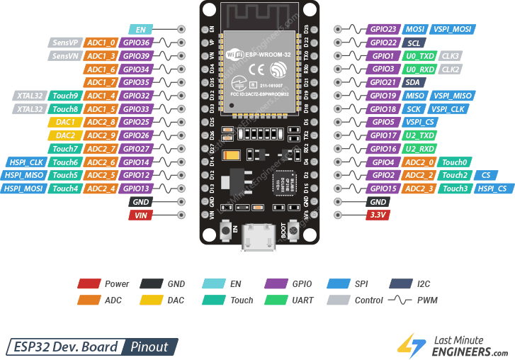
A0 is pin 33, so to read AO use analogRead(33); (if analogRead(A0) is not recognized)
-
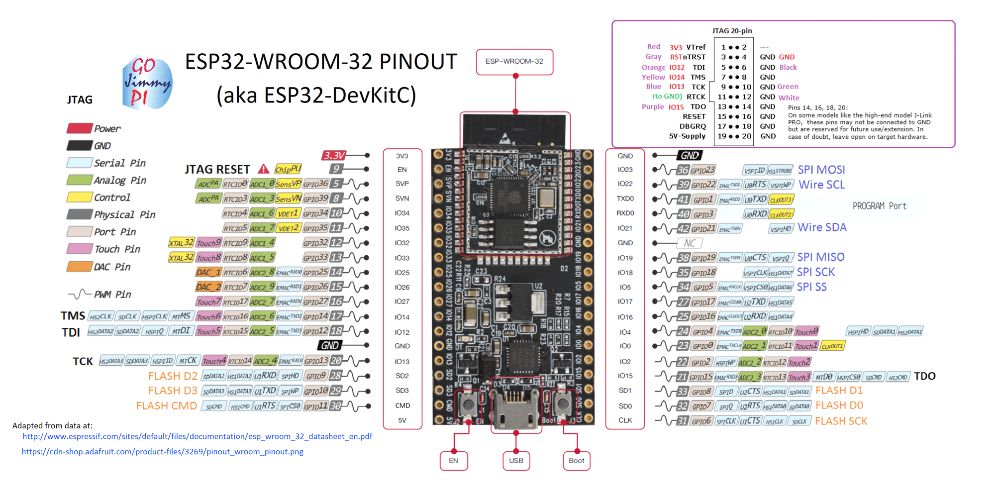
ESP32 WROOM: we have a separate page for it: https://github.com/ultranoise/learn-esp32/wiki/esp32-learn-WROOM-examples
-
ESP32 Dev MODULE (Arduino Board name) (38 pins!!)
led pin = 1;
- WEMOS D1 MINI ESP32 (40 pins)
led pin = 2;

Arduino Core for ESP32: https://github.com/espressif/arduino-esp32
-
ADC2 is used by the Wi-Fi driver. Therefore the application can only use ADC2 when the Wi-Fi driver has not started.
-
ADC is highly sensitive to low power supply: unstable or low power supplies (e.g. your lapotop usb port) generate extremely noisy readings.
-
The ESP32 ADC can be sensitive to noise leading to large discrepancies in ADC readings. To minimize noise, users may connect a 0.1uF capacitor to the ADC input pad in use (this capacitor is often included at developer boards, but check it).
-
Not all dev modules have a built-in led!
ESP32 Wroom32 DevKit has total 25 GPIOs out of that few pins are Input only Pins (so NO digitalWrite on them). Also not all pins have input pullup, you need external pullup on these pins when using as input pullup.
GPIO 34, 35, 36, 39
GPIO0 pin is used as a bootstrapping pin, and should be low to enter UART download mode. Make sure it is not pulled low by a peripheral device during boot or the firmware will not start!
GPIO2 pin is used as a bootstrapping pin, and should be low to enter UART download mode. Make sure it is not pulled high by a peripheral device during boot or you will not be able to flash a firmware to the module!
GPIO06 through GPIO11 are reserved for the FLASH. You cannot use them at all!
GPIO12 is used as a bootstrapping pin to select output voltage of an internal regulator which powers the flash chip (VDD_SDIO). This pin has an internal pulldown so if left unconnected it will read low at reset (selecting default 3.3V operation). Make sure it is not pulled high by a peripheral device during boot or the module might not be able to start!
GPIO15 can be used to stop debug output on Serial during boot. If pulled low there will be no output on the Serial port during the boot process. This can be helpful in battery powered applications where you do not want to use the Serial port at all to reduce power consumption.
GPIO34-39 can only be set as input mode and do not have software pullup or pulldown functions
GPIO37 and 38 are not available on most modules
(In my board, blue LED at GPIO2, red LED is POWER)
int ledPin = 2;  //check the pinout of your board

void setup()
{
    pinMode(ledPin, OUTPUT);
    Serial.begin(115200);
}

void loop()
{
    Serial.println("Hello, world!");
    digitalWrite(ledPin, HIGH);
    delay(500);
    digitalWrite(ledPin, LOW);
    delay(500);
}
Touch Sensor Design with ESP32: https://github.com/espressif/esp-iot-solution/blob/master/documents/touch_pad_solution/touch_sensor_design_en.md
// ESP32 Touch Test
// Just test touch pin - Touch3 is T3 which is on GPIO 15.

void setup()
{
  Serial.begin(115200);
  delay(1000); // give me time to bring up serial monitor
  Serial.println("ESP32 Touch Test");
}

void loop()
{
  Serial.println(touchRead(T3));  // get value using T3
  delay(100);
}
// ESP32 analog read
// read pin is ADC2_3 which is on GPIO 15.

void setup()
{
  Serial.begin(115200);
  delay(1000); // give me time to bring up serial monitor
  Serial.println("ESP32 Analog Test");
}

void loop()
{
  int sensorValue = analogRead(15);  // read the input on analog pin 15:
  Serial.println(sensorValue);      // print out the value you read:
  delay(100);
}
/*
 WiFi Web Server LED Blink

 A simple web server that lets you blink an LED via the web.
 This sketch will print the IP address of your board
 to the Serial monitor. From there, you can open that address in a web browser
 to turn on and off the LED on pin 5.

 If the IP address of your shield is yourAddress:
 http://yourAddress/H turns the LED on
 http://yourAddress/L turns it off

 This example is written for a network using WPA encryption. For
 WEP or WPA, change the Wifi.begin() call accordingly.

 Circuit:
 * LED attached to pin 2

 */

#include <WiFi.h>

const char* ssid     = "red";
const char* password = "muygeheim";

WiFiServer server(80);

void setup()
{
    Serial.begin(115200);
    pinMode(2, OUTPUT);      // set the LED pin mode

    delay(10);

    // We start by connecting to a WiFi network

    Serial.println();
    Serial.println();
    Serial.print("Connecting to ");
    Serial.println(ssid);

    WiFi.begin(ssid, password);

    while (WiFi.status() != WL_CONNECTED) {
        delay(500);
        Serial.print(".");
    }

    Serial.println("");
    Serial.println("WiFi connected.");
    Serial.println("IP address: ");
    Serial.println(WiFi.localIP());

    server.begin();

}

int value = 0;

void loop(){
 WiFiClient client = server.available();   // listen for incoming clients

  if (client) {                             // if you get a client,
    Serial.println("New Client.");           // print a message out the serial port
    String currentLine = "";                // make a String to hold incoming data from the client
    while (client.connected()) {            // loop while the client's connected
      if (client.available()) {             // if there's bytes to read from the client,
        char c = client.read();             // read a byte, then
        Serial.write(c);                    // print it out the serial monitor
        if (c == '\n') {                    // if the byte is a newline character

          // if the current line is blank, you got two newline characters in a row.
          // that's the end of the client HTTP request, so send a response:
          if (currentLine.length() == 0) {
            // HTTP headers always start with a response code (e.g. HTTP/1.1 200 OK)
            // and a content-type so the client knows what's coming, then a blank line:
            client.println("HTTP/1.1 200 OK");
            client.println("Content-type:text/html");
            client.println();

            // the content of the HTTP response follows the header:
            client.print("Click <a href=\"/H\">here</a> to turn the LED on pin 2 on.<br>");
            client.print("Click <a href=\"/L\">here</a> to turn the LED on pin 2 off.<br>");

            // The HTTP response ends with another blank line:
            client.println();
            // break out of the while loop:
            break;
          } else {    // if you got a newline, then clear currentLine:
            currentLine = "";
          }
        } else if (c != '\r') {  // if you got anything else but a carriage return character,
          currentLine += c;      // add it to the end of the currentLine
        }

        // Check to see if the client request was "GET /H" or "GET /L":
        if (currentLine.endsWith("GET /H")) {
          digitalWrite(2, HIGH);               // GET /H turns the LED on
        }
        if (currentLine.endsWith("GET /L")) {
          digitalWrite(2, LOW);                // GET /L turns the LED off
        }
      }
    }
    // close the connection:
    client.stop();
    Serial.println("Client Disconnected.");
  }
}
#include <WiFi.h>
#include <WiFiAP.h>

WiFiServer server(80);

String header;

//variables for the physical interaction
String LED_ONE_STATE = "off";
String LED_TWO_STATE = "off";
String LED_THREE_STATE = "off";


const int GPIO_PIN_NUMBER_22 = 2;
const int GPIO_PIN_NUMBER_23 = 23;
const int GPIO_PIN_NUMBER_15 = 26;

// Your name for the access point.
const char *APssid = "Plant";

//a few variables for the access point
boolean connected = false;     //wifi connection
bool accesspoint = true;       //acccess point mode
boolean APconnected = false;   //access point connected
bool registered = false;       //wifi handler registration


// Set your Static IP address (dummy values initialization)
IPAddress staIP(192,168,0,129);         //Board static IP
IPAddress staGateway(192,168,0,1);      //Gateway IP
IPAddress staSubnet(255,255,255,0);     //Subnet range
IPAddress primaryDNS(192, 168, 0, 1);   //optional
IPAddress secondaryDNS(8, 8, 4, 4);     //optional


void setup() {
  Serial.begin(115200);
  pinMode(GPIO_PIN_NUMBER_22, OUTPUT);
  pinMode(GPIO_PIN_NUMBER_23, OUTPUT);
  pinMode(GPIO_PIN_NUMBER_15, OUTPUT);

  digitalWrite(GPIO_PIN_NUMBER_22, LOW);
  digitalWrite(GPIO_PIN_NUMBER_23, LOW);
  digitalWrite(GPIO_PIN_NUMBER_15, LOW);

  /*
  Serial.print("Connecting to ");
  Serial.println(WIFI_NAME);
  WiFi.begin(WIFI_NAME, WIFI_PASSWORD);
  while (WiFi.status() != WL_CONNECTED) {
    delay(1000);
    Serial.print("Trying to connect to Wifi Network");
  }
  Serial.println("");
  Serial.println("Successfully connected to WiFi network");
  Serial.println("IP address: ");
  Serial.println(WiFi.localIP());
  */

  Serial.println();
  Serial.println("Configuring access point...");

  //register event handler
  if(!registered){
    registered = true;
    WiFi.onEvent(WiFiEvent);
  }

  //Create Access Point
    WiFi.mode(WIFI_AP);
    WiFi.softAP(APssid);
    Serial.println("Wait 100 ms for access point to start AP_START...");
    delay(100);

    Serial.println("Set softAPConfig");
    IPAddress Ip(192, 168, 0, 1);       //We fix an IP easy to recover without serial monitor
    IPAddress NMask(255, 255, 255, 0);
    WiFi.softAPConfig(Ip, Ip, NMask);

    IPAddress myIP1 = WiFi.softAPIP();
    Serial.print("Access Point Created!!");
    Serial.print("IP address: ");
    Serial.println(myIP1);
    APconnected = true;
    connected = true;

  //begin html server
  server.begin();
}

void loop(){

  //here is where we react to the clients connecting through the webserver
  WiFiClient client = server.available();   //if a client is connected to the server
  if (client) {
    Serial.println("New Client is requesting web page");
    String current_data_line = "";
    while (client.connected()) {
      if (client.available()) {
        char new_byte = client.read();
        Serial.write(new_byte);
        header += new_byte;
        if (new_byte == '\n') {

          if (current_data_line.length() == 0) //begin loading the website
          {

            client.println("HTTP/1.1 200 OK");
            client.println("Content-type:text/html");
            client.println("Connection: close");
            client.println();


            //this is where we react to the actions made by the user
            //depending on the actions we are loading different parts of the html

            //in the following case we react to the actions on the buttons
            if (header.indexOf("LED0=ON") != -1)
            {
              Serial.println("GPIO23 LED is ON");
              LED_ONE_STATE = "on";
              digitalWrite(GPIO_PIN_NUMBER_22, HIGH);
            }
            if (header.indexOf("LED0=OFF") != -1)
            {
              Serial.println("GPIO23 LED is OFF");
              LED_ONE_STATE = "off";
              digitalWrite(GPIO_PIN_NUMBER_22, LOW);
            }
            if (header.indexOf("LED1=ON") != -1)
            {
              Serial.println("GPIO23 LED is ON");
              LED_TWO_STATE = "on";
              digitalWrite(GPIO_PIN_NUMBER_23, HIGH);
            }
            if (header.indexOf("LED1=OFF") != -1)
            {
              Serial.println("GPIO23 LED is OFF");
              LED_TWO_STATE = "off";
              digitalWrite(GPIO_PIN_NUMBER_23, LOW);
            }
            if (header.indexOf("LED2=ON") != -1)
            {
              Serial.println("GPIO15 LED is ON");
              LED_THREE_STATE = "on";
              digitalWrite(GPIO_PIN_NUMBER_15, HIGH);
            }
            if(header.indexOf("LED2=OFF") != -1) {
              Serial.println("GPIO15 LED is OFF");
              LED_THREE_STATE = "off";
              digitalWrite(GPIO_PIN_NUMBER_15, LOW);
            }

            //this is the part where we load the rest of the html
            client.println("<!DOCTYPE html><html>");
            client.println("<head><meta name=\"viewport\" content=\"width=device-width, initial-scale=1\">");
            client.println("<link rel=\"icon\" href=\"data:,\">");
            //set background color
            client.println("<body style=\"background-color:blue;\"> ");
            client.println("</body>");
            //set fonts
            client.println("<style>html { font-family: Helvetica; display: inline-block; margin: 0px auto; text-align: center;}");
            client.println(".button { background-color: #4CAF50; border: 2px solid #4CAF50;; color: white; padding: 15px 32px; text-align: center; text-decoration: none; display: inline-block; font-size: 16px; margin: 4px 2px; cursor: pointer; }");
            client.println("text-decoration: none; font-size: 30px; margin: 2px; cursor: pointer;}");
            // Web Page Heading
            client.println("</style></head>");
            client.println("<body><center><h1>ESP32 Web server example</h1></center>");
            client.println("<center><h2>Web Server Example header h2</h2></center>" );
            client.println("<center><h2>Press on button to turn on led and off button to turn off LED</h3></center>");
            client.println("<form><center>");
            //here we are adding dynamic information to the html
            //in this case, we add the led state to a fix text
            client.println("<p> LED one is " + LED_ONE_STATE + "</p>");
            // If the PIN_NUMBER_22State is off, it displays the ON button
             client.println("<center> <button class=\"button\" name=\"LED0\" value=\"ON\" type=\"submit\">LED0 ON</button>") ;
             client.println("<button class=\"button\" name=\"LED0\" value=\"OFF\" type=\"submit\">LED0 OFF</button><br><br>");
             client.println("<p>LED two is " + LED_TWO_STATE + "</p>");
             client.println("<button class=\"button\" name=\"LED1\" value=\"ON\" type=\"submit\">LED1 ON</button>");
             client.println("<button class=\"button\" name=\"LED1\" value=\"OFF\" type=\"submit\">LED1 OFF</button> <br><br>");
             client.println("<p>LED three is " + LED_THREE_STATE + "</p>");
             client.println ("<button class=\"button\" name=\"LED2\" value=\"ON\" type=\"submit\">LED2 ON</button>");
             client.println ("<button class=\"button\" name=\"LED2\" value=\"OFF\" type=\"submit\">LED2 OFF</button></center>");
            client.println("</center></form></body></html>");
            client.println();
            break;
          }
          else
          {
            current_data_line = "";
          }
        }
        else if (new_byte != '\r')
        {
          current_data_line += new_byte;
        }
      }
    }
    // Clear the header variable
    header = "";
    // Close the connection
    client.stop();
    Serial.println("Client disconnected.");
    Serial.println("");
  }
}

//wifi event handler
void WiFiEvent(WiFiEvent_t event){
    switch(event) {
      case SYSTEM_EVENT_STA_GOT_IP:
          //When connected set
          Serial.print("WiFi connected! IP address: ");
          Serial.println(WiFi.localIP());

          connected = true;
          break;
      case SYSTEM_EVENT_STA_DISCONNECTED:
          Serial.println("WiFi lost connection");
          connected = false;
          break;
    }
}
// Load Wi-Fi library
#include <WiFi.h>
#include <DNSServer.h>

const byte DNS_PORT = 53;
DNSServer dnsServer;
IPAddress apIP(192, 168, 4, 1);

// Replace with your wifi information
const char* ssid     = "Plant-Access-Point";  //access point name
//const char* password = "123456789";

// Set web server port number to 80
WiFiServer server(80);


String responseHTML = ""
  "<!DOCTYPE html><html><head><title>CaptivePortal</title></head><body>"
  "<h1>Hello Noor, I am your Plant!</h1><p>This is a captive portal example. All requests will "
  "be redirected here. Now let's do something creative</p></body></html>";

// Variable to store the HTTP request
String header;


void setup() {
  Serial.begin(115200);

  // Connect to Wi-Fi network with SSID and password
  Serial.print("Setting AP (Access Point)…");
  // Remove the password parameter, if you want the AP (Access Point) to be open
  WiFi.softAP(ssid);

  IPAddress IP = WiFi.softAPIP();
  Serial.print("AP IP address: ");
  Serial.println(IP);

  // if DNSServer is started with "*" for domain name, it will reply with
  // provided IP to all DNS request
  dnsServer.start(DNS_PORT, "*", apIP);

  server.begin();
}

void loop(){
  dnsServer.processNextRequest();
  WiFiClient client = server.available();   // Listen for incoming clients

  if (client) {                             // If a new client connects,
    Serial.println("New Client.");          // print a message out in the serial port
    String currentLine = "";                // make a String to hold incoming data from the client
    while (client.connected()) {
      if (client.available()) {
        char c = client.read();
        if (c == '\n') {
          if (currentLine.length() == 0) {
            client.println("HTTP/1.1 200 OK");
            client.println("Content-type:text/html");
            client.println();
            client.print(responseHTML);
            break;
          } else {
            currentLine = "";
          }
        } else if (c != '\r') {
          currentLine += c;
        }
      }
    }

    // Close the connection
    client.stop();
    Serial.println("Client disconnected.");
    Serial.println("");
  }
}
#include <WiFi.h>
#include <WiFiUdp.h>

/* WiFi network name and password */
const char * ssid = "red";
const char * pwd = "muygeheim";

// IP address to send UDP data to.
// it can be ip address of the server or
// a network broadcast address
// here is broadcast address
const char * udpAddress = "192.168.2.105";
const int udpPort = 44444;

//create UDP instance
WiFiUDP udp;

void setup(){
  Serial.begin(115200);

  //Connect to the WiFi network
   WiFi.begin(ssid, pwd);
  Serial.println("");

  // Wait for connection
  while (WiFi.status() != WL_CONNECTED) {
    delay(500);
    Serial.print(".");
  }
  Serial.println("");
  Serial.print("Connected to ");
  Serial.println(ssid);
  Serial.print("IP address: ");
  Serial.println(WiFi.localIP());
  //This initializes udp and transfer buffer
  udp.begin(udpPort);
}

void loop(){
  //data will be sent to server
  uint8_t buffer[50] = "hello world";
  //send hello world to server
  udp.beginPacket(udpAddress, udpPort);
  udp.write(buffer, 11);
  udp.endPacket();
  memset(buffer, 0, 50);
  //processing incoming packet, must be called before reading the buffer
  udp.parsePacket();
  //receive response from server, it will be HELLO WORLD
  if(udp.read(buffer, 50) > 0){
    Serial.print("Server to client: ");
    Serial.println((char *)buffer);
  }
  //Wait for 1 second
  delay(1000);
}
For running this code you also need to install the OSC library in Arduino.
How? Menu Sketch -> Include Library -> Manage Libraries -> search OSC -> find OSC by Adrian Freed (only this one) and Install
If you want to test it with Pure Data or Max, you can download a receiver patch.
#include <WiFi.h>
#include <WiFiUdp.h>
#include <OSCMessage.h>
#include <WiFiAP.h>


//IP address to send UDP data to:
// either use the ip address of the server or
// a network broadcast address
IPAddress udpAddress(192, 168, 0, 2);  //just a dummy, it can be configured via browser
int udpPort = 44444;                   //just a dummy, it can be configured via browser

// Your name for access point.
const char *APssid = "Martin";


//The udp library class
WiFiUDP udp;

int touchValue = 0;

boolean connected = false;     //wifi connection
bool accesspoint = true;       //acccess point mode
boolean APconnected = false;   //access point connected
bool registered = false;       //wifi handler registration


// Set your Static IP address (dummy values initialization)
IPAddress staIP(192,168,0,129);         //Board static IP
IPAddress staGateway(192,168,0,1);      //Gateway IP
IPAddress staSubnet(255,255,255,0);     //Subnet range
IPAddress primaryDNS(192, 168, 0, 1);   //optional
IPAddress secondaryDNS(8, 8, 4, 4);     //optional


void setup(){
  // Initilize hardware serial:
  Serial.begin(115200);

  Serial.println();
  Serial.println("Configuring access point...");

  //register event handler
  if(!registered){
    registered = true;
    WiFi.onEvent(WiFiEvent);
  }

 //Create Access Point
    WiFi.mode(WIFI_AP);
    WiFi.softAP(APssid);
    Serial.println("Wait 100 ms for AP_START...");
    delay(100);

    Serial.println("Set softAPConfig");
    IPAddress Ip(192, 168, 0, 1);       //We fix an IP easy to recover without serial monitor
    IPAddress NMask(255, 255, 255, 0);
    WiFi.softAPConfig(Ip, Ip, NMask);

    IPAddress myIP1 = WiFi.softAPIP();
    Serial.print("Access Point Created!!");
    Serial.print("IP address: ");
    Serial.println(myIP1);
    APconnected = true;
    connected = true;
}

void loop(){
  //only send data when connected
  if(connected){
    //Send a packet

    touchValue = touchRead(T3);  //GPIO 15
    Serial.print("touch: ");
    Serial.print(touchValue);
    Serial.println("");

    OSCMessage msg("/esp");
    msg.add((float) touchValue);

    udp.beginPacket(udpAddress, udpPort);
    msg.send(udp);
    udp.endPacket();
    msg.empty();
  }
  //Wait for 25ms
  delay(25);
}


//wifi event handler
void WiFiEvent(WiFiEvent_t event){
    switch(event) {
      case SYSTEM_EVENT_STA_GOT_IP:
          //When connected set
          Serial.print("WiFi connected! IP address: ");
          Serial.println(WiFi.localIP());
          //initializes the UDP state
          //This initializes the transfer buffer
          udp.begin(WiFi.localIP(),udpPort);
          connected = true;
          break;
      case SYSTEM_EVENT_STA_DISCONNECTED:
          Serial.println("WiFi lost connection");
          connected = false;
          break;
    }
}
For running this code you also need to install the OSC library in Arduino.
How? Menu Sketch -> Include Library -> Manage Libraries -> search OSC -> find OSC by Adrian Freed (only this one) and click Install
If you want to test it with Pure Data or Max, you can download a receiver patch.
#include <WiFi.h>
#include <WiFiUdp.h>
#include <OSCMessage.h>


// WiFi network name and password:
const char * networkName = "red";
const char * networkPswd = "muygeheim";

//IP address to send UDP data to:
// either use the ip address of the server or
// a network broadcast address
const IPAddress udpAddress(192, 168, 2, 105);
const int udpPort = 44444;


//Are we currently connected?
boolean connected = false;

//The udp library class
WiFiUDP udp;

int touchValue = 0;

void setup(){
  // Initilize hardware serial:
  Serial.begin(115200);

  //Connect to the WiFi network
  connectToWiFi(networkName, networkPswd);
}

void loop(){
  //only send data when connected
  if(connected){
    //Send a packet

    touchValue = touchRead(T3);  //GPIO 15
    Serial.print("touch: ");
    Serial.print(touchValue);
    Serial.println("");

    OSCMessage msg("/esp");
    msg.add((float) touchValue);

    udp.beginPacket(udpAddress, udpPort);
    msg.send(udp);
    udp.endPacket();
    msg.empty();
  }
  //Wait for 25ms
  delay(25);
}

void connectToWiFi(const char * ssid, const char * pwd){
  Serial.println("Connecting to WiFi network: " + String(ssid));

  // delete old config
  WiFi.disconnect(true);
  //register event handler
  WiFi.onEvent(WiFiEvent);

  //Initiate connection
  WiFi.begin(ssid, pwd);

  Serial.println("Waiting for WIFI connection...");
}

//wifi event handler
void WiFiEvent(WiFiEvent_t event){
    switch(event) {
      case SYSTEM_EVENT_STA_GOT_IP:
          //When connected set
          Serial.print("WiFi connected! IP address: ");
          Serial.println(WiFi.localIP());
          //initializes the UDP state
          //This initializes the transfer buffer
          udp.begin(WiFi.localIP(),udpPort);
          connected = true;
          break;
      case SYSTEM_EVENT_STA_DISCONNECTED:
          Serial.println("WiFi lost connection");
          connected = false;
          break;
    }
}
Quite easy using ESP32-BLE-MIDI library available at the libraries manager: https://github.com/max22-/ESP32-BLE-MIDI (install it)
It includes two possible connection modes: client or host.
MacOS:
I have tested it in MacOSC and it works flawlessly. First configure the midi device at "Audio & Midi Setup" > click on the Bluetooth icon on the upper bar > connect to the esp32 midi device. It will directly appear as another midi device in your system. Go to the same place to disconnect or every time you need to connect.
Windows:
It seems is necessary to use additional software to route bluetooth midi to our favourite audio software. In particular it is necessary to use Midiberry (https://www.microsoft.com/de-at/p/midiberry/9n39720h2m05?rtc=1&activetab=pivot:overviewtab) to get Midi Bluetooth which is able to deliver these data to another MIDI port. For this reason it is necessary to use a virtual MIDI server (like loopMidi http://www.tobias-erichsen.de/software/loopmidi.html) which finally will communicate to the audio software. The idea would be ESP32 > Midiberry > Loopback > Live Ableton. You can follow this tutorial: http://newbodyfresher.linclip.com/how-to-use-with-daw
Here the basic code for all platforms:
#include <Arduino.h>
#include <BLEMidi.h>

void setup() {
  Serial.begin(115200);
  Serial.println("Initializing bluetooth");
  BLEMidiServer.begin("Kike MIDI device");
  Serial.println("Waiting for connections...");
  //BLEMidiServer.enableDebugging();  // Uncomment if you want to see some debugging output from the library (not much for the server class...)
}

void loop() {
  if(BLEMidiServer.isConnected()) {             // If we've got a connection, we send an A4 during one second, at full velocity (127)
      BLEMidiServer.noteOn(0, 69, 127);
      delay(1000);
      BLEMidiServer.noteOff(0, 69, 127);        // Then we make a delay of one second before returning to the beginning of the loop
      delay(1000);
  }
  delay(1);   // we feed the ESP32 watchdog when there is no connection
}
Now try this code for sending control change data:
#include <Arduino.h>
#include <BLEMidi.h>

void setup() {
  Serial.begin(115200);
  Serial.println("Initializing bluetooth");
  BLEMidiServer.begin("Kike MIDI device");
  Serial.println("Waiting for connections...");
  //BLEMidiServer.enableDebugging();  // Uncomment if you want to see some debugging output from the library (not much for the server class...)
}

void loop() {
  if(BLEMidiServer.isConnected()) {             // If we've got a connection, we send an A4 during one second, at full velocity (127)

      BLEMidiServer.controlChange(0, 122, touchRead(T3));

      delay(20);
  }
  delay(1);   // we feed the ESP32 watchdog when there is no connection
}
This code implements a complete solution to deal with OSC data using ESP32s as access points or connected to networks. It also provides a webserver to change the boards mode (access point to STA and vice-versa) and many functions to handle it in an efficient way.
The code also provides a solution to hardreset the board when it has been badly configured for a wifi and it is not possible to interface anymore via network. Therefore, the pin D15 of your board has to be always pulled-up or it will continuously reset.
/////////////////////////////////////////////////////////////////////////
/// ESP32 Tangible Core  . OSC Client Generic Solution                 //
///                                                                    //
/// This sends OSC data to a host                                      //
/// configured as access point or connected to a wifi network          //
//                                                                     //
//  It uses pin 15 (LOW) to hardreset the board in access point mode   //
//  so you need to connect pin 15 to HIGH to make it work.             //
/// [email protected] may 2019                                      //
/////////////////////////////////////////////////////////////////////////
//                                                                     //
// Install OSC library by Adrian Freed (and not arduinoOSC or ardOSC)  //
/////////////////////////////////////////////////////////////////////////

#include <WiFi.h>
#include <WiFiClient.h>
#include <WiFiUdp.h>
#include <OSCMessage.h>
#include <WiFiAP.h>
#include <ESPmDNS.h>
#include <WebServer.h>
#include "esp_wifi.h"

#include "EEPROM.h"
#include <Wire.h>

#include "lwip/inet.h"
#include "lwip/dns.h"

//Using Wifi UDP for OSC and Server to configure the board with a browser
WiFiUDP udp;
WebServer server(80);


// WiFi network name and password:
String network;
String password;

// Your desired credentials for access point.
const char *APssid = "EG1-accessPoint";

//first IP address to send UDP data to:
// either use the ip address of the server or a network broadcast address
IPAddress udpAddress(192, 168, 0, 2);  //just a dummy, it can be configured via browser
int udpPort = 44444;                   //just a dummy, it can be configured via browser


//A few flags
boolean connected = false;     //wifi connection
bool accesspoint = true;       //acccess point mode
boolean APconnected = false;   //access point connected
bool registered = false;       //wifi handler registration
bool shouldReboot = false;     //flag to use from web update to reboot the ESP

//OSC message types (create yours)
OSCMessage msg_test("/esp/test");

//overall delay added to loop() to avoid overflow of OSC messages
float delayProgram = 5;


// Set your Static IP address (dummy values initialization)
IPAddress staIP(192,168,0,129);         //Board static IP
IPAddress staGateway(192,168,0,1);      //Gateway IP
IPAddress staSubnet(255,255,255,0);     //Subnet range
IPAddress primaryDNS(192, 168, 0, 1);   //optional
IPAddress secondaryDNS(8, 8, 4, 4);     //optional

IPAddress clientsAddress[10];           //ten clients can be connected in access point mode
int numClients = 0;


//EEPROM
#define EEPROM_SIZE 256
int addr = 0; // the current address in the EEPROM (i.e. which byte we're going to write to next)


//////////////////////
// setup
//////////////////////
void setup(){
  // Initialize hardware serial:
  Serial.begin(115200);
  Serial.println();
  Serial.println("/////////////////////////////");
  Serial.println("Generic ESP32 solution");
  Serial.println("Tangible Music Lab 2019 ([email protected])");
  Serial.println("/////////////////////////////");

  pinMode(LED_BUILTIN, OUTPUT);
  pinMode(15, INPUT);             //hardreset pin

  ///eeprom init
  EEPROM.begin(EEPROM_SIZE);

  // First check hardreset pin
  // A hardreset pin will save us when a network configuration fails!!
  if(digitalRead(15) == LOW){
    Serial.println();
    Serial.println("RESET pin 15 is low!!");

    resetBoard();   // reset board, fix Access Point mode and save to EEPROM

  } else {
    Serial.println();
    Serial.println("RESET pin 15 is high!!");

    confSettings();  //read configuration from eeprom in both AP (access point) or STA (Station network) modes
  }


  ///Create WIFI for AP or STA modes
  if(accesspoint == false){
    // No access point, connect to STA
    Serial.println();
    Serial.print("Connecting to WIFI... ");
    Serial.println(network);

    //Connect to the WiFi network
    connectToWiFi(network, password);

  } else {
    Serial.println();
    Serial.println("Configuring access point...");

    //register event handler
    if(!registered){
      registered = true;
      WiFi.onEvent(WiFiEvent);
    }

    WiFi.mode(WIFI_AP);
    WiFi.softAP(APssid);
    Serial.println("Wait 100 ms for AP_START...");
    delay(100);

    Serial.println("Set softAPConfig");
    IPAddress Ip(192, 168, 0, 1);       //We fix an IP easy to recover without serial monitor
    IPAddress NMask(255, 255, 255, 0);
    WiFi.softAPConfig(Ip, Ip, NMask);

    IPAddress myIP1 = WiFi.softAPIP();
    Serial.print("AP IP address: ");
    Serial.println(myIP1);
    APconnected = true;
  }

  // A simple web server will allow us configuring a bit the board
  // start web server
  server.on("/", handleRoot);       //handleRoot is a function dealing with the actions on the server via browser
  server.onNotFound(handleNotFound);// a default function dealing with errors during browsing

  server.begin();
  Serial.println();
  Serial.println("Web Server started");
  Serial.println();

  Serial.println("OSC port: " + String(udpPort)); //inform about the port
  Serial.println();

}


void loop(){

  //after a change of mode we should reboot the board
  if(shouldReboot){
    Serial.println("Rebooting...");
    delay(100);
    ESP.restart();
  }

  //handle wifi server clients connected and configuring via browser (always?)
  server.handleClient();

  // OSC data transmission
  if(connected || APconnected){ //only send OSC data when connected

    if(accesspoint){   // ESP32 AS ACCESS POINT: send to all connected clients
       for(int i = 0; i < numClients; i++) {
          msg_test.add((unsigned int) millis());  // some dummy data (milliseconds running this code)
          udp.beginPacket(clientsAddress[i], udpPort);
          msg_test.send(udp);
          udp.endPacket();
          msg_test.empty();
       }
    }
    else{ ///CONNECTED TO STA WIFI
      //OSC send
      msg_test.add((unsigned int) millis());  // some dummy data (milliseconds running)
      udp.beginPacket(udpAddress, udpPort);
      msg_test.send(udp);
      udp.endPacket();
      msg_test.empty();
    }

  }
  //Wait for some micro or mili-seconds to avoid overflow of OSC messages
  delay(delayProgram);
}


//////////////////
///FUNCTIONS
//////////////////


/////////////////////////////////////////////////////////////
//wifi basic STA connection function
void connectToWiFi(String ssid, String pwd){

  //register event handler. This allows receiving messages of connection, disconnections, etc
  if(!registered){
    registered = true;
    WiFi.onEvent(WiFiEvent);
  }

  // delete old config if already connected
  WiFi.disconnect(true);

  //we will simply use gateway as DNS address
  primaryDNS = staGateway;
  secondaryDNS = staGateway;


  Serial.print("connecting to: ");
  Serial.println(ssid);

  //connect to wifi
  WiFi.begin(ssid.c_str(), pwd.c_str());  //I use c_str() as we have to convert strings to arrays of characters
  //Comment below for DHCP
  WiFi.config(staIP, staGateway, staSubnet, primaryDNS,secondaryDNS);   //fix IP at network

  //unfortunately the following status is not always well caught, I will comment it
  //until the bug is solved
  //while (WiFi.status() != WL_CONNECTED) { //wait until connected
  //      delay(500);
  //      Serial.print(".");
  //  }

  //instead of waiting until connected, let´s give the ESP a bit of time to connect
  //if previous bug is solved, the following line can be removed
  delay(2000);

  //Some info
  Serial.println("");
  Serial.println("WiFi connected!");
  Serial.print("IP address: ");
  Serial.println(WiFi.localIP());
  Serial.print("ESP Mac Address: ");
  Serial.println(WiFi.macAddress());
  Serial.print("Subnet Mask: ");
  Serial.println(WiFi.subnetMask());
  Serial.print("Gateway IP: ");
  Serial.println(WiFi.gatewayIP());
  Serial.print("DNS: ");
  Serial.println(WiFi.dnsIP());


}

/////////////////////////////////////////////////////////////
// wifi event handler
// These are all the messages we receive from Wifi Manager
void WiFiEvent(WiFiEvent_t event){
    Serial.printf("[WiFi-event] event: %d\n", event);

    switch(event) {
       case SYSTEM_EVENT_STA_GOT_IP:    //WE HAVE GOT AN IP!!
          //When connected set
          Serial.print("WiFi connected! IP address: ");

          //initialize UDP state when we get an IP
          //This initializes the transfer buffer
          udp.begin(WiFi.localIP(),udpPort);
          connected = true;
          break;

       case SYSTEM_EVENT_STA_DISCONNECTED:  //try to reconnect if disconnected
          //Serial.println("WiFi lost connection");
          Serial.println("Disconnected from WiFi access point");
          connected = false;

          WiFi.disconnect(true);

          //Initiate connection
          connectToWiFi(network, password);
          delay(1000);
          break;

        case SYSTEM_EVENT_WIFI_READY:
            Serial.println("WiFi interface ready");
            break;
        case SYSTEM_EVENT_SCAN_DONE:
            Serial.println("Completed scan for access points");
            break;
        case SYSTEM_EVENT_STA_START:
            Serial.println("WiFi client started");
            break;
        case SYSTEM_EVENT_STA_STOP:
            Serial.println("WiFi clients stopped");
            break;
        case SYSTEM_EVENT_STA_CONNECTED:
            Serial.println("Connected to STA");
            break;
        case SYSTEM_EVENT_STA_AUTHMODE_CHANGE:
            Serial.println("Authentication mode of access point has changed");
            break;
        case SYSTEM_EVENT_STA_LOST_IP:
            Serial.println("Lost IP address and IP address is reset to 0");
            break;
        case SYSTEM_EVENT_STA_WPS_ER_SUCCESS:
            Serial.println("WiFi Protected Setup (WPS): succeeded in enrollee mode");
            break;
        case SYSTEM_EVENT_STA_WPS_ER_FAILED:
            Serial.println("WiFi Protected Setup (WPS): failed in enrollee mode");
            break;
        case SYSTEM_EVENT_STA_WPS_ER_TIMEOUT:
            Serial.println("WiFi Protected Setup (WPS): timeout in enrollee mode");
            break;
        case SYSTEM_EVENT_STA_WPS_ER_PIN:
            Serial.println("WiFi Protected Setup (WPS): pin code in enrollee mode");
            break;
        case SYSTEM_EVENT_AP_START:
            Serial.println("WiFi access point started");
            APconnected = true;
            connected = true;
            updateStations();
            break;
        case SYSTEM_EVENT_AP_STOP:
            Serial.println("WiFi access point  stopped");
            break;
        case SYSTEM_EVENT_AP_STACONNECTED:
            Serial.println("Client connected");
            connected = true;
            break;
        case SYSTEM_EVENT_AP_STADISCONNECTED:
            Serial.println("Client disconnected");
            updateStations();
            break;
        case SYSTEM_EVENT_AP_STAIPASSIGNED:
            Serial.println("Assigned IP address to client");
            updateStations();
            connected = true;
            break;
        case SYSTEM_EVENT_AP_PROBEREQRECVED:
            Serial.println("Received probe request");
            break;
        case SYSTEM_EVENT_GOT_IP6:
            Serial.println("IPv6 is preferred");
            break;
        case SYSTEM_EVENT_ETH_START:
            Serial.println("Ethernet started");
            break;
        case SYSTEM_EVENT_ETH_STOP:
            Serial.println("Ethernet stopped");
            break;
        case SYSTEM_EVENT_ETH_CONNECTED:
            Serial.println("Ethernet connected");
            break;
        case SYSTEM_EVENT_ETH_DISCONNECTED:
            Serial.println("Ethernet disconnected");
            break;
        case SYSTEM_EVENT_ETH_GOT_IP:
            Serial.println("Obtained IP address");
        break;
    }
}

///////////////////////////////////////////////////////////////////////
// Handling information about connected clients in access point mode
// For sending OSC data to clients we need to know their IPs and this
// function makes the work.
void updateStations() {

  wifi_sta_list_t stationList;
  esp_wifi_ap_get_sta_list(&stationList);

  //update number of clients (stations connected)
  numClients = stationList.num;

  Serial.println("-----------------");
  Serial.print("Number of connected stations: ");
  Serial.println(stationList.num);
  Serial.println("-----------------");

  //Now obtain their Mac addresses and IP addresses
  tcpip_adapter_sta_list_t adapter_sta_list;
  memset(&adapter_sta_list, 0, sizeof(adapter_sta_list));

  ESP_ERROR_CHECK(tcpip_adapter_get_sta_list(&stationList, &adapter_sta_list));

  //we have to convert station information to IPAdress type of arduino
  for(int i = 0; i < adapter_sta_list.num; i++) {
    tcpip_adapter_sta_info_t station = adapter_sta_list.sta[i];
    printf("%d - mac: %.2x:%.2x:%.2x:%.2x:%.2x:%.2x - IP: %s\n", i + 1,
    station.mac[0], station.mac[1], station.mac[2],
    station.mac[3], station.mac[4], station.mac[5],
    ip4addr_ntoa(&(station.ip)));

    String ipi = ip4addr_ntoa(&(station.ip));
    String strIP = ipi;

    int Parts[4] = {0,0,0,0};
    int Part = 0;
    for ( int i=0; i<strIP.length(); i++ ) {
      char c = strIP[i];
      if ( c == '.' ) {
        Part++;
        continue;
      }
      Parts[Part] *= 10;
      Parts[Part] += c - '0';
    }

    //finally this is the array of clients ip addresses
    IPAddress ipo( Parts[0], Parts[1], Parts[2], Parts[3] );
    clientsAddress[i]= ipo;

  }

}


////////////////////////////////////////////////////////
//// Webserver HTML code
//
// This is a long string we can dynamically change
///////////////////////////////////////////////////////

String SendHTML(uint8_t led1stat,uint8_t led2stat){
  String ptr = "<!DOCTYPE HTML>";
ptr +="<html>";
ptr +="<head>";
ptr +="<meta name = \"viewport\" content = \"width = device-width, initial-scale = 1.0, maximum-scale = 1.0, user-scalable=0\">";
ptr +="<title>ESP32 - Tangible Core</title>";
ptr +="<style>";
ptr +="\"body { background-color: #808080; font-family: Arial, Helvetica, Sans-Serif; Color: #000000; }\"";
ptr +="</style>";
ptr +="</head>";
ptr +="<body>";
ptr +="<h1>ESP32 - Tangible Core</h1>";
ptr +="<FORM action=\"/\" method=\"post\">";
ptr +="<P>";

if(accesspoint){                              //html code when access point. it allows connecting to a network using a form
  ptr +="<P>";
  ptr +="ESP32 Configured as Access Point";
  ptr +="<P>";
  ptr +="OSC Port: ";
  ptr +=String(udpPort);
  ptr +="<P>";
  ptr +="Number of connected Devices: ";
  ptr +=String(numClients);
  ptr +="<P>";
  if (numClients > 0) {
    ptr +="<P>";
    ptr +="Clients IPs: ";

    for(int i = 0; i < numClients; i++) {
      ptr +=" ";
      ptr +=clientsAddress[i].toString();;
    }
  }
  ptr +="<br>";
  // now create a few input fields for entering information about the network to connect
  ptr +="</P>";
  ptr +="To change Access Point mode and connect to a Wifi: <br>";
  ptr +="</P>";
  ptr +="Wifi name<br>";
  ptr +="<INPUT type=\"text\" name=\"ssid_name\"<BR>";

  ptr +="</P>";
  ptr +="Password<br>";
  ptr +="<INPUT type=\"text\" name=\"password_name\"<BR>";

  ptr +="</P>";
  ptr +="IP of the computer you will send OSC<br>";
  ptr +="<INPUT type=\"text\" name=\"host_IP\"<BR>";

  ptr +="</P>";
  ptr +="Your IP number in the new Wifi Network<br>";
  ptr +="<INPUT type=\"text\" name=\"fixed_IP\"<BR>";

  ptr +="</P>";
  ptr +="Gateway IP <br>";
  ptr +="<INPUT type=\"text\" name=\"gateway_IP\"<BR>";

  ptr +="</P>";
  ptr +="OSC Port<br>";
  ptr +="<INPUT type=\"text\" name=\"host_Port\"<BR>";

  ptr +="</P>";
  ptr +="Activate Wifi Now clicking on Send<br>";

  ptr +="<INPUT type=\"submit\" value=\"Send\">";  //the button to submit information
  ptr +="</P>";


} else{                             //html code when STA mode. it only allows setting as access point
  ptr +="<P>";
  ptr +="ESP32 Connected to WIFI: " + String(network);
  ptr +="<P>";
  ptr +="OSC Port: ";
  ptr +=String(udpPort);
  ptr +="<P>";
  ptr +="Sending OSC to IP: ";
  ptr +=IpAddress2String(udpAddress);
  ptr +="<P>";
  ptr +="<br>";

  ptr +="Configuration:";
  ptr +="</P>";
  ptr +="Configure ESP32 board as Access Point: ";
  ptr +="</P>";
  ptr +="<INPUT type=\"checkbox\" name=\"mode_ap\"<BR>Activate Access Point<br>";
  ptr +="</P>";

  ptr +="<INPUT type=\"submit\" value=\"Send\">";   //a button to reset to acccess point
  ptr +="</P>";
  ptr +="</P>";
  ptr +="</P>";
}

ptr +="</FORM>";
ptr +="</body>";
ptr +="</html>";
return ptr;
}


//////////////////////////////////////////
// webserver methods
//////////////////////////////////////////
void handleRoot()                             //receives actions from the webserver and decides what to do
{
  //Browse information received
  for(int i=0; i<server.args(); i++) {
    Serial.println(server.arg(i));
  }
  if (server.hasArg("mode_ap") && server.args()==1) {     //when it is STA mode and we want to change to access point
      handle_APchange();
  }
  else{
    if (server.hasArg("ssid_name") && server.args()==6) { //when it is access point and we want to change to STA
      handleSsid();
    }
    else {
      server.send(200, "text/html", SendHTML(true,true)); //refresh the website or the browser will show an empty page
    }
 }


}

//funtion changing to access point mode
void handle_APchange() {

  Serial.println();
  Serial.println("Configuring as Access Point");

  //send a response
  server.send(200, "text/html", SendHTML(true,true));

  //LOAD INFORMATION IN EEPROM
  Serial.println();
  Serial.println("writing data in eeprom memory");

  Serial.print("Writing Data:");
    //writing strings at memory. First arg sets a byte address, second the data to store

    //clear eeprom first
    for (int i = 0 ; i < EEPROM_SIZE ; i++) {
      EEPROM.write(i, 0);
    }

    //then set flag to Access Point, the rest was cleared
    int address = 0;
    writeStringMem(0, "0");                   //flag for setting access point OR NOT (0=AP, 1=STA)

    delay(3000);
    shouldReboot = true;
}

//function to connect to a network
void handleSsid()
{
  //some aux strings to store information typed by user at the webserver
  String new_ssid;
  String new_passw;
  String new_fixed_ip;
  String new_host_ip;
  String new_host_port;
  String new_gateway_ip;

  //check data and load wifi data
  if (!server.hasArg("ssid_name")) return returnFail("BAD ARGS");
  new_ssid = server.arg("ssid_name");
  Serial.println("New SSID to connect: " + new_ssid);

  if (!server.hasArg("password_name")) return returnFail("BAD ARGS");
  new_passw = server.arg("password_name");
  Serial.println("New passw to connect " + new_passw);

  if (!server.hasArg("fixed_IP")) return returnFail("BAD ARGS");
  new_fixed_ip = server.arg("fixed_IP");
  Serial.println("IP at new network  " + new_fixed_ip);

  if (!server.hasArg("host_IP")) return returnFail("BAD ARGS");
  new_host_ip = server.arg("host_IP");
  Serial.println("IP of host at new network  " + new_host_ip);

  if (!server.hasArg("gateway_IP")) return returnFail("BAD ARGS");
  new_gateway_ip = server.arg("gateway_IP");
  Serial.println("Gateway IP  " + new_gateway_ip);

  if (!server.hasArg("host_Port")) return returnFail("BAD ARGS");
  new_host_port = server.arg("host_Port");
  Serial.println("OSC port to change  " + new_host_port);

  //send a response
  server.send(200, "text/html", SendHTML(true,true));

  //LOAD INFORMATION IN EEPROM
  Serial.println();
  Serial.println("writing data in eeprom memory");

  String data = new_ssid;


  //writing strings in flash memory. First arg sets a byte address, second the data to store
    Serial.print("Writing Data:");
    Serial.println(data);


    //clear eeprom first
    for (int i = 0 ; i < EEPROM_SIZE ; i++) {
      EEPROM.write(i, 0);
    }

    int address = 0;
    writeStringMem(0, "1");                   //flag for setting access point OR NOT (0=AP, 1=STA)

    address = 2; // as the flag "1" is two bytes long
    writeStringMem(2, String(new_ssid.length()));           //SSID string length

    address = 20;       //20 is arbitrary, to leave some space for other flags
    writeStringMem(address, new_ssid);

    address = 86;       //SSIDs can be 32 character long (65 bytes)
    writeStringMem(address, new_passw);

    address = 130;       //passw max is 20 char long (41 bytes)
    writeStringMem(address, new_host_ip);                 //IP is 16 bythes long

    address = 170;       //an IP is max 15 char long (31 bytes)
    writeStringMem(address, new_fixed_ip);

    address = 200;       //an IP is max 15 char long (31 bytes)
    writeStringMem(address, new_host_port);

    address = 216;       //an IP is max 15 char long (31 bytes)
    writeStringMem(address, new_gateway_ip);


  //We should reboot the esp32 now
  Serial.println();
  Serial.println("data written in eeprom memory");
  delay(3000);
  shouldReboot = true;
}

// other necessary handling functions
void returnFail(String msg){
  server.sendHeader("Connection", "close");
  server.sendHeader("Access-Control-Allow-Origin", "*");
  server.send(500, "text/plain", msg + "\r\n");
}

void returnOK(){
  server.sendHeader("Connection", "close");
  server.sendHeader("Access-Control-Allow-Origin", "*");
  server.send(200, "text/plain", "OK\r\n");
}

void handleNotFound(){
  String message = "File Not Found\n\n";
  message += "URI: ";
  message += server.uri();
  message += "\nMethod: ";
  message += (server.method() == HTTP_GET)?"GET":"POST";
  message += "\nArguments: ";
  message += server.args();
  message += "\n";
  for (uint8_t i=0; i<server.args(); i++){
    message += " " + server.argName(i) + ": " + server.arg(i) + "\n";
  }
  server.send(404, "text/plain", message);
}

// eeprom functions
void writeStringMem(char add,String data){
  int _size = data.length();
  int i;
  for(i=0;i<_size;i++)
  {
    EEPROM.write(add+i,data[i]);
  }
  EEPROM.write(add+_size,'\0');   //Add termination null character for String Data
  EEPROM.commit();
}


// eeprom functions
String read_String(char add){
  int i;
  char data[100]; //Max 100 Bytes
  int len=0;
  unsigned char k;
  k=EEPROM.read(add);
  while(k != '\0' && len<500)   //Read until null character
  {
    k=EEPROM.read(add+len);
    data[len]=k;
    len++;
  }
  data[len]='\0';
  return String(data);
}

///////////////////////////////////////////////////////
/// reset board to Access Point mode and clear eeprom
////
void resetBoard(){
  Serial.println();
  Serial.println("I will reset this ESP32");

  //LOAD INFORMATION IN EEPROM
  Serial.println();
  Serial.println("writing original data in eeprom memory");

    //clear eeprom
    for (int i = 0 ; i < EEPROM_SIZE ; i++) {
      EEPROM.write(i, 0);
    }

    int address = 0;
    writeStringMem(0, "0");                   //flag for setting access point OR NOT (0=AP, 1=STA)

    Serial.println("ESP32 should be in AP mode, rebooting...");
    delay(3000);
    shouldReboot = true;

}


//////////////////////////////////////////////////
/// Configuration Settings loaded from EEPROM
void confSettings(){
  Serial.println();
  Serial.println("* Reading EEPROM:");

  String d;
  int address;

  // the first byte is a flag (0 or 1) informing about wifi modes
  address = 0;
  d = read_String(address);
  Serial.print("- AccesPoint flag (0= AP, 1=STA):");
  Serial.println(d);
  if(d.toInt()==0){
    accesspoint = true;
  } else {
    accesspoint = false;
  }

  address = 2; //we know the flag is always 2 bytes long
  d = read_String(2);
  //Serial.print("- SSID Length:");
  //Serial.println(d);

  d = read_String(20);  //reading ssid, address (20) is arbitrary, the following are too.
  Serial.print("- SSID:");
  Serial.println(d);
  network = d;

  d = read_String(86);
  Serial.print("- Password:");
  Serial.println(d);
  password = d;

  d = read_String(130);
  Serial.print("- host ip:");
  Serial.println(d);
  if(!accesspoint ) udpAddress = string2IP(d);


  d = read_String(170);
  Serial.print("- ip at new network:");
  Serial.println(d);
  if(!accesspoint ) staIP = string2IP(d);


  d = read_String(200);
  Serial.print("- OSC port:");
  Serial.println(d);
  if(!accesspoint ) udpPort = d.toInt();  //cause it can be empty at the beginning


  d = read_String(216);
  Serial.print("- Gateway ip:");
  Serial.println(d);
  if(!accesspoint ) staGateway = string2IP(d);

}

//function to convert a string to an IPAdress type
IPAddress string2IP(String strIP){

    int Parts[4] = {0,0,0,0};
    int Part = 0;
    for ( int i=0; i<strIP.length(); i++ ) {
      char c = strIP[i];
      if ( c == '.' ) {
        Part++;
        continue;
      }
      Parts[Part] *= 10;
      Parts[Part] += c - '0';
    }

    IPAddress ipo( Parts[0], Parts[1], Parts[2], Parts[3] );
    return ipo;
}

//function to convert IPAdress type to string
String IpAddress2String(const IPAddress& ipAddress){
  return String(ipAddress[0]) + String(".") +\
  String(ipAddress[1]) + String(".") +\
  String(ipAddress[2]) + String(".") +\
  String(ipAddress[3])  ;
}
You can send MIDI over an rtp connection. This is the mecanism used at AppleMIDI.
The great new is that it is possible to make session management and device syncronisation.
Use:
-
install AppleMIDI library in Arduino and follow the steps here
-
in Mac, at AUDIO/MIDI Setup, choose the network icon and add a new session. Then add a new participant (the ESP32) in the directory. You need to know its name, its IP and port. The program in the ESP32 may print it via serial.
-
Your MIDI device will appear at any software available as if it was connected via USB.
This is an example of how it worked for me: {{:tamlab:projects:internal:taco:screenshot_2018-12-19_at_11.51.03.png?400|}}
// These need to be included when using standard Ethernet
#include <WiFi.h>
#include <WiFiClient.h>
#include <WiFiUdp.h>

#include "AppleMidi.h"

char ssid[] = "red"; //  your network SSID (name)
char pass[] = "muygeheim";    // your network password (use for WPA, or use as key for WEP)

unsigned long t0 = millis();
bool isConnected = false;

APPLEMIDI_CREATE_INSTANCE(WiFiUDP, AppleMIDI); // see definition in AppleMidi_Defs.h

// -----------------------------------------------------------------------------
//
// -----------------------------------------------------------------------------
void setup()
{
  // Serial communications and wait for port to open:
  Serial.begin(115200);
  //while (!Serial) {

    //; // wait for serial port to connect. Needed for Leonardo only
  //}

  Serial.print(F("Getting IP address..."));


  WiFi.begin(ssid, pass);

  while (WiFi.status() != WL_CONNECTED) {
    delay(500);
    Serial.print(F("."));
  }
  Serial.println(F(""));
  Serial.println(F("WiFi connected"));


  Serial.println();
  Serial.print(F("IP address is "));
  Serial.println(WiFi.localIP());

  Serial.println(F("OK, now make sure you an rtpMIDI session that is Enabled"));
  Serial.print(F("Add device named Arduino with Host/Port "));
  Serial.print(WiFi.localIP());
  Serial.println(F(":5004"));
  Serial.println(F("Then press the Connect button"));
  Serial.println(F("Then open a MIDI listener (eg MIDI-OX) and monitor incoming notes"));

  // Create a session and wait for a remote host to connect to us
  AppleMIDI.begin("test");

  AppleMIDI.OnConnected(OnAppleMidiConnected);
  AppleMIDI.OnDisconnected(OnAppleMidiDisconnected);

  AppleMIDI.OnReceiveNoteOn(OnAppleMidiNoteOn);
  AppleMIDI.OnReceiveNoteOff(OnAppleMidiNoteOff);

  Serial.println(F("Sending NoteOn/Off of note 45, every second"));
}

// -----------------------------------------------------------------------------
//
// -----------------------------------------------------------------------------
void loop()
{
  // Listen to incoming notes
  AppleMIDI.run();

  // send a note every second
  // (dont cáll delay(1000) as it will stall the pipeline)
  if (isConnected && (millis() - t0) > 1000)
  {
    t0 = millis();
    //   Serial.print(".");

    byte note = 45;
    byte velocity = 55;
    byte channel = 1;

    AppleMIDI.sendNoteOn(note, velocity, channel);
    AppleMIDI.sendNoteOff(note, velocity, channel);
  }
}

// ====================================================================================
// Event handlers for incoming MIDI messages
// ====================================================================================

// -----------------------------------------------------------------------------
// rtpMIDI session. Device connected
// -----------------------------------------------------------------------------
void OnAppleMidiConnected(uint32_t ssrc, char* name) {
  isConnected  = true;
  Serial.print(F("Connected to session "));
  Serial.println(name);
}

// -----------------------------------------------------------------------------
// rtpMIDI session. Device disconnected
// -----------------------------------------------------------------------------
void OnAppleMidiDisconnected(uint32_t ssrc) {
  isConnected  = false;
  Serial.println(F("Disconnected"));
}

// -----------------------------------------------------------------------------
//
// -----------------------------------------------------------------------------
void OnAppleMidiNoteOn(byte channel, byte note, byte velocity) {
  Serial.print(F("Incoming NoteOn from channel:"));
  Serial.print(channel);
  Serial.print(F(" note:"));
  Serial.print(note);
  Serial.print(F(" velocity:"));
  Serial.print(velocity);
  Serial.println();
}

// -----------------------------------------------------------------------------
//
// -----------------------------------------------------------------------------
void OnAppleMidiNoteOff(byte channel, byte note, byte velocity) {
  Serial.print(F("Incoming NoteOff from channel:"));
  Serial.print(channel);
  Serial.print(F(" note:"));
  Serial.print(note);
  Serial.print(F(" velocity:"));
  Serial.print(velocity);
  Serial.println();
}
Only the ESP32-S2 and ESP32-S3 models allow native USB MIDI communication. Previous ESP32 models do not allow this possibility: https://github.com/cnlohr/espusb/issues/45 However for ESP32-S1 you can always use an external USB host: https://create.arduino.cc/projecthub/139994/plug-any-usb-device-on-an-esp8266-e0ca8a
We succedded using the ESP32-S3 with Adafruit Tiny USB library for Arduino (https://github.com/adafruit/Adafruit_TinyUSB_Arduino)

How to:
-
Install Adafruit's TinyUSB library
-
Install the MIDI Library by Forty Seven Effects (https://github.com/FortySevenEffects/arduino_midi_library) as it is shown in the picture:

-
Connect the board to the USB port labelled USB (not the COM)
-
Configure the board in Arduino as in the following caption (use same configuration for USB mode, Upload Mode, etc):

-
Open Adafruit TinyUSB MIDI midi_test.ino example (from Arduino/File/Examples or from https://github.com/adafruit/Adafruit_TinyUSB_Arduino/blob/master/examples/MIDI/midi_test/midi_test.ino)
-
Upload this example and RESET the board.
-
Run a DAW to receive MIDI data

-
To upload code again, it is necessary to enter boot mode. If not, no serial port will be available in Arduino. For that, press and hold BOOT button, then press and release RESET Button, and finally release BOOT. The serial port will be accessible again. Do not forget to reset the board to run the new code.
-
To use Control Change: simply type something like MIDI.sendControlChange(11, random(60,90), 1);
Here an example of receiving CC11 and notes and the same time in Live Ableton:

- Alternative 1: create your signal and play it through the DAC (8 bits!!), and amplifying it:
Examples and resources: https://www.xtronical.com/testing-the-dacaudio-hardware/
For example, a triangular wave form:
void setup()
{
}

void loop()
{
  for(int i=0;i<256;i++)
    dacWrite(25,i);
  for(int i=254;i>0;i--)
    dacWrite(25,i);
}
- Alternative 2: with a I2S audio interface. ESP32 has two I2S peripherals. They can be configured to input and output sample data. They also supports DMA to stream sample data without needing CPU operations. I2S output can also be routed directly to the Digital to Analog Converter output (GPIO25 and GPIO26) without needing external I2S codec.
In this case I used a PCM5102 I2S audio codec, with BCK pin = 26, LRCK pin = 25, DIN pin = 22:
#include "driver/i2s.h"
#include "freertos/queue.h"
#include <pgmspace.h>

#include "soundsample.h"


//i2s configuration
int i2s_num = 0; // i2s port number
i2s_config_t i2s_config = {
     .mode = (i2s_mode_t)(I2S_MODE_MASTER | I2S_MODE_TX),
     .sample_rate = 16000,
     .bits_per_sample = I2S_BITS_PER_SAMPLE_16BIT,
     .channel_format = I2S_CHANNEL_FMT_RIGHT_LEFT,
     .communication_format = (i2s_comm_format_t)(I2S_COMM_FORMAT_I2S | I2S_COMM_FORMAT_I2S_MSB),
     .intr_alloc_flags = ESP_INTR_FLAG_LEVEL1, // high interrupt priority
     .dma_buf_count = 8,
     .dma_buf_len = 64   //Interrupt level 1
    };

i2s_pin_config_t pin_config = {
    .bck_io_num = 26, //this is BCK pin
    .ws_io_num = 25, // this is LRCK pin
    .data_out_num = 22, // this is DATA output pin
    .data_in_num = -1   //Not used
};

int i2s_write_sample_nb(uint32_t sample) {
  return i2s_write_bytes((i2s_port_t)i2s_num, (const char *)&sample, sizeof(uint32_t), 100);
}

//Main function to play samples from PROGMEM
void playPROGMEMsample(const uint32_t* audioSample) {


  uint32_t counter = 0;
  //initialize i2s with configurations above
  i2s_driver_install((i2s_port_t)i2s_num, &i2s_config, 0, NULL);
  i2s_set_pin((i2s_port_t)i2s_num, &pin_config);
  //set sample rates of i2s to sample rate of wav file
  i2s_set_sample_rates((i2s_port_t)i2s_num, 16000);


  uint32_t readData;

  while (audioSample)  {
    readData = pgm_read_dword(&audioSample[counter++]);
    if (readData == NULL) break;
    i2s_write_sample_nb(readData);
  }

  i2s_driver_uninstall((i2s_port_t)i2s_num); //stop & destroy i2s driver
}

void setup() {

  Serial.begin(115200);
  Serial.println("Serial connection OK");
  playPROGMEMsample(sample1);
}

void loop() {


}
and the sound data (soundsample.h you need to include): {{ :tamlab:projects:internal🌮soundsample.zip |}}
Multicast over wifi has been used to low levels of success, usually to a point of being so negative that multicast over wifi is not allowed. Multicast over wifi experiences high packet error rates, no acknowledgements, and low data rate. This draft reviews these problems found with multicast over wifi.
Multicast Wifi Problem Statement: https://tools.ietf.org/id/draft-mcbride-mboned-wifi-mcast-problem-statement-01.html
It is possible to create a responder and query.
This is an example of announcing and finding services:
#include <WiFi.h>
#include <ESPmDNS.h>

const char* ssid     = "eb1";
const char* password = "goodman1";

void setup() {
    Serial.begin(115200);
    WiFi.begin(ssid, password);
    while (WiFi.status() != WL_CONNECTED) {
        delay(250);
        Serial.print(".");
    }
    Serial.println("");
    Serial.print("Connected to ");
    Serial.println(ssid);
    Serial.print("IP address: ");
    Serial.println(WiFi.localIP());

    if (!MDNS.begin("ESP32_Browser")) {
        Serial.println("Error setting up MDNS responder!");
        while(1){
            delay(1000);
        }
    }
}

void loop() {
    browseService("http", "tcp");
    delay(1000);
    browseService("arduino", "tcp");
    delay(1000);
    browseService("workstation", "tcp");
    delay(1000);
    browseService("smb", "tcp");
    delay(1000);
    browseService("afpovertcp", "tcp");
    delay(1000);
    browseService("ftp", "tcp");
    delay(1000);
    browseService("ipp", "tcp");
    delay(1000);
    browseService("printer", "tcp");
    delay(10000);
}

void browseService(const char * service, const char * proto){
    Serial.printf("Browsing for service _%s._%s.local. ... ", service, proto);
    int n = MDNS.queryService(service, proto);
    if (n == 0) {
        Serial.println("no services found");
    } else {
        Serial.print(n);
        Serial.println(" service(s) found");
        for (int i = 0; i < n; ++i) {
            // Print details for each service found
            Serial.print("  ");
            Serial.print(i + 1);
            Serial.print(": ");
            Serial.print(MDNS.hostname(i));
            Serial.print(" (");
            Serial.print(MDNS.IP(i));
            Serial.print(":");
            Serial.print(MDNS.port(i));
            Serial.println(")");
        }
    }
    Serial.println();
}
For projects where users (or clients) need to update the project firmware themselves without being in the lab and without any serial connection (oh yeah!).
This is an example...
-
You, developer, have to upload this code once. This would be the first firmware version. In this case, it is just a typical led blink example but with all the necessary OTA code. For programming your own project you will have to extend this code.
-
If you ask your users to update to a new firmware, you will have to send them the new compiled binary (a .ino.bin file). Users will connect to the board wireleslly for uploading the new firmware. This ino.bin can be obtained using "Exporting Compiled Binary" at the menu "Sketch" of Arduino.
-
The user has to connect the board to the WLAN and know the IP of the board. In this case, the IP is also written in the serial monitor. Probably your professional firmware should offer more friendly alternatives (mDNS, info servers, etc) to obtain the IP.
-
The user types this IP (or alias) in her browser. Once the server web page is loaded, she types --- user: admin, password: admin (change this values in the code, please).
-
The user clicks on "upload" (select the .ino.bin file of your new firmware) and then clicks on "update"
-
The progress bar will show the flashing process. Finally the esp32 will restart automatically with the new firmware
#include <WiFi.h>
#include <WiFiClient.h>
#include <WebServer.h>
#include <ESPmDNS.h>
#include <Update.h>

const char* host = "esp32";
const char* ssid = "red";
const char* password = "muygeheim";

//variabls for blinking an LED with Millis
const int led = 2; // ESP32 Pin to which onboard LED is connected
unsigned long previousMillis = 0;  // will store last time LED was updated
const long interval = 1000;  // interval at which to blink (milliseconds)
int ledState = LOW;  // ledState used to set the LED
WebServer server(80);

/* Style */
String style =
"<style>#file-input,input{width:100%;height:44px;border-radius:4px;margin:10px auto;font-size:15px}"
"input{background:#f1f1f1;border:0;padding:0 15px}body{background:#3498db;font-family:sans-serif;font-size:14px;color:#777}"
"#file-input{padding:0;border:1px solid #ddd;line-height:44px;text-align:left;display:block;cursor:pointer}"
"#bar,#prgbar{background-color:#f1f1f1;border-radius:10px}#bar{background-color:#3498db;width:0%;height:10px}"
"form{background:#fff;max-width:258px;margin:75px auto;padding:30px;border-radius:5px;text-align:center}"
".btn{background:#3498db;color:#fff;cursor:pointer}</style>";

/* Login page */
String loginIndex =
"<form name=loginForm>"
"<h1>ESP32 Login</h1>"
"<input name=userid placeholder='User ID'> "
"<input name=pwd placeholder=Password type=Password> "
"<input type=submit onclick=check(this.form) class=btn value=Login></form>"
"<script>"
"function check(form) {"
"if(form.userid.value=='admin' && form.pwd.value=='admin')"
"{window.open('/serverIndex')}"
"else"
"{alert('Error Password or Username')}"
"}"
"</script>" + style;

/* Server Index Page */
String serverIndex =
"<script src='https://ajax.googleapis.com/ajax/libs/jquery/3.2.1/jquery.min.js'></script>"
"<form method='POST' action='#' enctype='multipart/form-data' id='upload_form'>"
"<input type='file' name='update' id='file' onchange='sub(this)' style=display:none>"
"<label id='file-input' for='file'>   Choose file...</label>"
"<input type='submit' class=btn value='Update'>"
"<br><br>"
"<div id='prg'></div>"
"<br><div id='prgbar'><div id='bar'></div></div><br></form>"
"<script>"
"function sub(obj){"
"var fileName = obj.value.split('\\\\');"
"document.getElementById('file-input').innerHTML = '   '+ fileName[fileName.length-1];"
"};"
"$('form').submit(function(e){"
"e.preventDefault();"
"var form = $('#upload_form')[0];"
"var data = new FormData(form);"
"$.ajax({"
"url: '/update',"
"type: 'POST',"
"data: data,"
"contentType: false,"
"processData:false,"
"xhr: function() {"
"var xhr = new window.XMLHttpRequest();"
"xhr.upload.addEventListener('progress', function(evt) {"
"if (evt.lengthComputable) {"
"var per = evt.loaded / evt.total;"
"$('#prg').html('progress: ' + Math.round(per*100) + '%');"
"$('#bar').css('width',Math.round(per*100) + '%');"
"}"
"}, false);"
"return xhr;"
"},"
"success:function(d, s) {"
"console.log('success!') "
"},"
"error: function (a, b, c) {"
"}"
"});"
"});"
"</script>" + style;

/* setup function */
void setup(void) {

pinMode(led,  OUTPUT);
  Serial.begin(115200);

  // Connect to WiFi network
  WiFi.begin(ssid, password);
  Serial.println("");

  // Wait for connection
  while (WiFi.status() != WL_CONNECTED) {
    delay(500);
    Serial.print(".");
  }
  Serial.println("");
  Serial.print("Connected to ");
  Serial.println(ssid);
  Serial.print("IP address: ");
  Serial.println(WiFi.localIP());

  /*use mdns for host name resolution*/
  if (!MDNS.begin(host)) { //http://esp32.local
    Serial.println("Error setting up MDNS responder!");
    while (1) {
      delay(1000);
    }
  }
  Serial.println("mDNS responder started");
  /*return index page which is stored in serverIndex */
  server.on("/", HTTP_GET, []() {
    server.sendHeader("Connection", "close");
    server.send(200, "text/html", loginIndex);
  });
  server.on("/serverIndex", HTTP_GET, []() {
    server.sendHeader("Connection", "close");
    server.send(200, "text/html", serverIndex);
  });
  /*handling uploading firmware file */
  server.on("/update", HTTP_POST, []() {
    server.sendHeader("Connection", "close");
    server.send(200, "text/plain", (Update.hasError()) ? "FAIL" : "OK");
    ESP.restart();
  }, []() {
    HTTPUpload& upload = server.upload();
    if (upload.status == UPLOAD_FILE_START) {
      Serial.printf("Update: %s\n", upload.filename.c_str());
      if (!Update.begin(UPDATE_SIZE_UNKNOWN)) { //start with max available size
        Update.printError(Serial);
      }
    } else if (upload.status == UPLOAD_FILE_WRITE) {
      /* flashing firmware to ESP*/
      if (Update.write(upload.buf, upload.currentSize) != upload.currentSize) {
        Update.printError(Serial);
      }
    } else if (upload.status == UPLOAD_FILE_END) {
      if (Update.end(true)) { //true to set the size to the current progress
        Serial.printf("Update Success: %u\nRebooting...\n", upload.totalSize);
      } else {
        Update.printError(Serial);
      }
    }
  });
  server.begin();
}

void loop(void) {
  server.handleClient();
  delay(1);

//loop to blink without delay
 unsigned long currentMillis = millis();
 if (currentMillis - previousMillis >= interval) {
 // save the last time you blinked the LED
 previousMillis = currentMillis;
 // if the LED is off turn it on and vice-versa:
 ledState = not(ledState);
 // set the LED with the ledState of the variable:
 digitalWrite(led,  ledState);
 }
}
analogWrite (from Arduino IDE) does not work on ESP32. You have to use a set of 'ledc' commands instead, e.g.:
int ledPin = 2;  // pin for PWM signals, e.g. led, motors, etc.

// Initialize channels
// channels 0-15, resolution 1-16 bits, freq limits depend on resolution
// ledcSetup(uint8_t channel, uint32_t freq, uint8_t resolution_bits);
ledcAttachPin(ledPin, 0); // assign Pin to channels: channel 0
ledcSetup(0, 30000, 8); // 30 kHz PWM, 8-bit resolution
ledcWrite(0, 254);  // duty cycle
more info/ tutorial on ESP32 PWM here: {{https://circuits4you.com/2018/12/31/esp32-pwm-example/ | https://circuits4you.com/2018/12/31/esp32-pwm-example/}}
also there is a library, that uses ledc commands to emulate analogWrite for ESP32:
{{https://github.com/ERROPiX/ESP32_AnalogWrite | https://github.com/ERROPiX/ESP32_AnalogWrite}}
Example:
#include <Arduino.h>
#include <analogWrite.h>

int step = 1;
int brightness = 0;

void setup() {
}

void loop() {
  brightness += brightStep;
  analogWrite(LED_BUILTIN, brightness);

  if ( brightness == 0 || brightness == 255 ) {
    brightStep = -brightStep;
  }

  delay(10);
}
I have tested i2S possibilities with the makerfabs board (integrating SD card slot, i2S decoder, amplifier and lcd). Here some notes:
Working with this boards: https://www.makerfabs.com/eps32-audio-player.html
Everything works by default (audio and wifi), and with mycropython main.py can be easily edited for our purposes with Thony.
- It is possible to code in micropython: https://www.makerfabs.com/wiki/index.php?title=MakaPython_Audio and for that it is necessary to flash the board with a custom firmware as the I2S module is not included in the default micropython firmware. It is necessary to install the .bin from https://github.com/miketeachman/micropython-esp32-i2s-examples For installing it I used ./esptool.py --chip esp32 --port /dev/cu.usbserial-020F1184 write_flash -z 0x1000 esp32-idf3-i2s-2020-05-13-v1-12.bin
I run the example play-mono-wav-from-sdcard.py with Thony and it worked well reading wav from sdcard. More infos about micropython here: https://github.com/Makerfabs/Makerfabs_FAQ/tree/master/MakePython
- There are as well Arduino options working ok: https://www.instructables.com/ESP32-Audio-Player/ and https://github.com/Makerfabs/Project_MakePython_Audio_Music however it is not clear: how to import Audio.h , the I2S lib which board should be used for compiling on Arduino -> explained here: https://github.com/Makerfabs/Makerfabs_FAQ/tree/master/Arduino_ESP32
http://www.lilygo.cn/prod_view.aspx?TypeId=50030&Id=1272&FId=t3:50030:3
https://github.com/lewisxhe/esp32-camera-screen
https://www.youtube.com/watch?v=m4Go1i1oBZM
Typical Problems: https://randomnerdtutorials.com/esp32-cam-troubleshooting-guide/
#elif defined(CAMERA_MODEL_TTGO_CAMERA_PLUS)
#define PWDN_GPIO_NUM     -1
#define RESET_GPIO_NUM    -1
#define XCLK_GPIO_NUM      4
#define SIOD_GPIO_NUM     18
#define SIOC_GPIO_NUM     23

#define Y9_GPIO_NUM       36
#define Y8_GPIO_NUM       37
#define Y7_GPIO_NUM       38
#define Y6_GPIO_NUM       39
#define Y5_GPIO_NUM       35
#define Y4_GPIO_NUM       26
#define Y3_GPIO_NUM       13
#define Y2_GPIO_NUM       34
#define VSYNC_GPIO_NUM     5
#define HREF_GPIO_NUM     27
#define PCLK_GPIO_NUM     25
Interesting code
Motion Detection
https://eloquentarduino.github.io/2020/01/motion-detection-with-esp32-cam-only-arduino-version/
https://eloquentarduino.github.io/2020/05/easier-faster-pure-video-esp32-cam-motion-detection/
https://eloquentarduino.github.io/2021/01/esp32-cam-motion-detection-with-photo-capture-rgb-version/
#define CAMERA_MODEL_TTGO_CAMERA_PLUS

#include "esp_camera.h"
#include "camera_pins.h"

#include <WiFi.h>
#include <WiFiUdp.h>
#include <OSCMessage.h>
#include <WiFiAP.h>

#define FRAME_SIZE FRAMESIZE_QVGA
#define WIDTH 320
#define HEIGHT 240
#define BLOCK_SIZE 8    // THE PARAMETER TO CHANGE
#define W (WIDTH / BLOCK_SIZE)
#define H (HEIGHT / BLOCK_SIZE)
#define BLOCK_DIFF_THRESHOLD 0.2
#define IMAGE_DIFF_THRESHOLD 0.1
#define DEBUG 0


uint16_t prev_frame[H][W] = { 0 };
uint16_t current_frame[H][W] = { 0 };

int blocks_changed;

//IP address to send UDP data to:
// either use the ip address of the server or
// a network broadcast address
IPAddress udpAddress(192, 168, 0, 2);  //just a dummy, it can be configured via browser
int udpPort = 44444;                   //just a dummy, it can be configured via browser

// Your name for access point.
const char *APssid = "paquito";


//The udp library class
WiFiUDP udp;

int touchValue = 0;

boolean connected = false;     //wifi connection
bool accesspoint = true;       //acccess point mode
boolean APconnected = false;   //access point connected
bool registered = false;       //wifi handler registration


// Set your Static IP address (dummy values initialization)
IPAddress staIP(192,168,0,129);         //Board static IP
IPAddress staGateway(192,168,0,1);      //Gateway IP
IPAddress staSubnet(255,255,255,0);     //Subnet range
IPAddress primaryDNS(192, 168, 0, 1);   //optional
IPAddress secondaryDNS(8, 8, 4, 4);     //optional


bool setup_camera(framesize_t);
bool capture_still();
int motion_detect();
void update_frame();
void print_frame(uint16_t frame[H][W]);


void setup() {
    Serial.begin(115200);
    Serial.println(setup_camera(FRAME_SIZE) ? "OK" : "ERR INIT");

    Serial.println();
    Serial.println("Configuring access point...");

  //register event handler
  if(!registered){
    registered = true;
    WiFi.onEvent(WiFiEvent);
  }

  //Create Access Point
    WiFi.mode(WIFI_AP);
    WiFi.softAP(APssid);
    Serial.println("Wait 100 ms for AP_START...");
    delay(100);

    Serial.println("Set softAPConfig");
    IPAddress Ip(192, 168, 0, 1);       //We fix an IP easy to recover without serial monitor
    IPAddress NMask(255, 255, 255, 0);
    WiFi.softAPConfig(Ip, Ip, NMask);

    IPAddress myIP1 = WiFi.softAPIP();
    Serial.print("Access Point Created!!");
    Serial.print("IP address: ");
    Serial.println(myIP1);
    APconnected = true;
    connected = true;
}


void loop() {


    if (!capture_still()) {
        Serial.println("Failed capture");
        delay(3000);

        return;
    }
    //only send data when connected
    if(connected){
      //Send a packet

      blocks_changed = motion_detect();

      OSCMessage msg("/esp");
      msg.add((int) blocks_changed);

      udp.beginPacket(udpAddress, udpPort);
      msg.send(udp);
      udp.endPacket();
      msg.empty();
    }

    update_frame();
    Serial.println("=================");
}


bool setup_camera(framesize_t frameSize) {
    camera_config_t config;

    config.ledc_channel = LEDC_CHANNEL_0;
    config.ledc_timer = LEDC_TIMER_0;
    config.pin_d0 = Y2_GPIO_NUM;
    config.pin_d1 = Y3_GPIO_NUM;
    config.pin_d2 = Y4_GPIO_NUM;
    config.pin_d3 = Y5_GPIO_NUM;
    config.pin_d4 = Y6_GPIO_NUM;
    config.pin_d5 = Y7_GPIO_NUM;
    config.pin_d6 = Y8_GPIO_NUM;
    config.pin_d7 = Y9_GPIO_NUM;
    config.pin_xclk = XCLK_GPIO_NUM;
    config.pin_pclk = PCLK_GPIO_NUM;
    config.pin_vsync = VSYNC_GPIO_NUM;
    config.pin_href = HREF_GPIO_NUM;
    config.pin_sscb_sda = SIOD_GPIO_NUM;
    config.pin_sscb_scl = SIOC_GPIO_NUM;
    config.pin_pwdn = PWDN_GPIO_NUM;
    config.pin_reset = RESET_GPIO_NUM;
    config.xclk_freq_hz = 20000000;
    config.pixel_format = PIXFORMAT_GRAYSCALE;
    config.frame_size = frameSize;
    config.jpeg_quality = 12;
    config.fb_count = 1;

    bool ok = esp_camera_init(&config) == ESP_OK;

    sensor_t *sensor = esp_camera_sensor_get();
    sensor->set_framesize(sensor, frameSize);

    return ok;
}


bool capture_still() {
    camera_fb_t *frame_buffer = esp_camera_fb_get();

    if (!frame_buffer)
        return false;

    // set all 0s in current frame
    for (int y = 0; y < H; y++)
        for (int x = 0; x < W; x++)
            current_frame[y][x] = 0;


    // down-sample image in blocks
    for (uint32_t i = 0; i < WIDTH * HEIGHT; i++) {
        const uint16_t x = i % WIDTH;
        const uint16_t y = floor(i / WIDTH);
        const uint8_t block_x = floor(x / BLOCK_SIZE);
        const uint8_t block_y = floor(y / BLOCK_SIZE);
        const uint8_t pixel = frame_buffer->buf[i];
        const uint16_t current = current_frame[block_y][block_x];

        // average pixels in block (accumulate)
        current_frame[block_y][block_x] += pixel;
    }

    // average pixels in block (rescale)
    for (int y = 0; y < H; y++)
        for (int x = 0; x < W; x++)
            current_frame[y][x] /= BLOCK_SIZE * BLOCK_SIZE;

#if DEBUG
    Serial.println("Current frame:");
    print_frame(current_frame);
    Serial.println("---------------");
#endif

    return true;
}


int motion_detect() {
    uint16_t changes = 0;
    const uint16_t blocks = (WIDTH * HEIGHT) / (BLOCK_SIZE * BLOCK_SIZE);

    for (int y = 0; y < H; y++) {
        for (int x = 0; x < W; x++) {
            float current = current_frame[y][x];
            float prev = prev_frame[y][x];
            float delta = abs(current - prev) / prev;

            if (delta >= BLOCK_DIFF_THRESHOLD) {
#if DEBUG
                Serial.print("diff\t");
                Serial.print(y);
                Serial.print('\t');
                Serial.println(x);
#endif

                changes += 1;
            }
        }
    }

    Serial.print("Changed ");
    Serial.print(changes);
    Serial.print(" out of ");
    Serial.println(blocks);

    return changes;
}


void update_frame() {
    for (int y = 0; y < H; y++) {
        for (int x = 0; x < W; x++) {
            prev_frame[y][x] = current_frame[y][x];
        }
    }
}


void print_frame(uint16_t frame[H][W]) {
    for (int y = 0; y < H; y++) {
        for (int x = 0; x < W; x++) {
            Serial.print(frame[y][x]);
            Serial.print('\t');
        }

        Serial.println();
    }
}

//wifi event handler
void WiFiEvent(WiFiEvent_t event){
    switch(event) {
      case SYSTEM_EVENT_STA_GOT_IP:
          //When connected set
          Serial.print("WiFi connected! IP address: ");
          Serial.println(WiFi.localIP());
          //initializes the UDP state
          //This initializes the transfer buffer
          udp.begin(WiFi.localIP(),udpPort);
          connected = true;
          break;
      case SYSTEM_EVENT_STA_DISCONNECTED:
          Serial.println("WiFi lost connection");
          connected = false;
          break;
    }
}
with camera_pins.h :
#if defined(CAMERA_MODEL_WROVER_KIT)
#define PWDN_GPIO_NUM    -1
#define RESET_GPIO_NUM   -1
#define XCLK_GPIO_NUM    21
#define SIOD_GPIO_NUM    26
#define SIOC_GPIO_NUM    27

#define Y9_GPIO_NUM      35
#define Y8_GPIO_NUM      34
#define Y7_GPIO_NUM      39
#define Y6_GPIO_NUM      36
#define Y5_GPIO_NUM      19
#define Y4_GPIO_NUM      18
#define Y3_GPIO_NUM       5
#define Y2_GPIO_NUM       4
#define VSYNC_GPIO_NUM   25
#define HREF_GPIO_NUM    23
#define PCLK_GPIO_NUM    22

#elif defined(CAMERA_MODEL_TTGO_CAMERA_PLUS)
#define PWDN_GPIO_NUM     -1
#define RESET_GPIO_NUM    -1
#define XCLK_GPIO_NUM      4
#define SIOD_GPIO_NUM     18
#define SIOC_GPIO_NUM     23

#define Y9_GPIO_NUM       36
#define Y8_GPIO_NUM       37
#define Y7_GPIO_NUM       38
#define Y6_GPIO_NUM       39
#define Y5_GPIO_NUM       35
#define Y4_GPIO_NUM       26
#define Y3_GPIO_NUM       13
#define Y2_GPIO_NUM       34
#define VSYNC_GPIO_NUM     5
#define HREF_GPIO_NUM     27
#define PCLK_GPIO_NUM     25

#else
#error "Camera model not selected"
#endif
First of all, install the necessary software for programming the board following these instructions
Find your ESP32 model, and look for the pinout of your board here . Understand the pins of your ESP32.
With how many bits is the analog input encoded in ESP32?
Connect a potentiometer to one analog Pin of the ESP32 and read the minimum and maximum value. Calculate the number of bits for encoding the analog input.
Unlike the teensy, the ESP32 does not offer USB host possibilities. Although we can program it via USB and transmit/receive serial messages, it is not possible to directly use USB MIDI or connect external USB devices (keyboards, mouse, USB Storage devices, printers, etc). ESP32 is usually interfaced using WLAN or Bluetooth.
For WLAN we can:
-
create an access point in the ESP32: your laptop will connect to this access point
-
connect the ESP32 to an existing wireless network (STA mode): your laptop and the ESP32 will connect to this network
Try the following code for creating an access point with you ESP32 and transmitting one value via OSC from the board to your computer.
Receive the values in your computer with:
-
Pure Data: download an example here
-
Max Msp: download an example here
-
Live: download the Connection Kit and use the object TouchOSC
and make a noise with these examples.
MIDI can be implemented over any transport protocol (USB, Serial, Wifi, Bluetooth, etc). Here we will test and check the functionality of MIDI over Bluetooth.
First: check the two examples I provide here
Second: adapt your USB MIDI sequencer for using Bluetooth.
Quickly reading your sensors doesn't mean that the values obtained:
-
match the expected range of values used in your synthesizer -> you need to scale them
-
are not noisy -> you have to filter inherent noise
-
change in a way which makes it difficult to create expressive gestures (too linear, too exponential, etc) -> you need to remap them
- Test the EWMA adapative filtering library. Here is the documentation
#include <Arduino.h>
#include <Ewma.h>

Ewma adcFilter1(0.1);   // Less smoothing - faster to detect changes, but more prone to noise
Ewma adcFilter2(0.01);  // More smoothing - less prone to noise, but slower to detect changes

void setup()
{
    Serial.begin(115200);
}

void loop()
{
    int raw = analogRead(15);
    float filtered1 = adcFilter1.filter(raw);
    float filtered2 = adcFilter2.filter(raw);
    Serial.printf("Raw=%d, Filter1=%.3f, Filter2=%.3f", raw, filtered1, filtered2);

    delay(100);
}
- Practice linear scaling using the map() function of arduino
#include <Arduino.h>
#include <Ewma.h>

Ewma adcFilter1(0.1);   // Less smoothing - faster to detect changes, but more prone to noise
Ewma adcFilter2(0.01);  // More smoothing - less prone to noise, but slower to detect changes

void setup()
{
    Serial.begin(115200);
}

void loop()
{
    int raw = analogRead(15);
    raw = map(raw, 0, 4095, 0, 255);  //linearly change the range from 4096 to 256 values
    float filtered1 = adcFilter1.filter(raw);
    float filtered2 = adcFilter2.filter(raw);
    Serial.printf("Raw=%d, Filter1=%.3f, Filter2=%.3f", raw, filtered1, filtered2);

    delay(100);
}
- Non-linear mapping is usually made implementing functions of various libraries:
-
In Arduino: [Multimap]https://playground.arduino.cc/Main/MultiMap/ or fscale or multipoint
-
In Pd you can use the "mapping" library
-
In Max you can use the mapping toolbox by IRCAM
Deadline 6 April
Practice USB MIDI and OSC together: Build a gestural controller plus a sequencer
-
Take three sensors from the box of sensors. Design an OSC gestural controller with them. You can transmit BT-MIDI or OSC-MIDI.
-
Find a Sound Mapping for this gestural controller: make it sound. Practice how to scale, adapt or filter the values of the sensors to obtain the values you need for the mapping.
-
Combine your USB MIDI sequencer with the gestural controller and prepare a two minutes improvisation with them.