Twitter to Teletype - swindonmakers/wiki GitHub Wiki
Note: There is a github repo, and a blog post for this project.
- People
- Feature List
- Notes on the ASR-33
- Questions and Issues to be Resolved
- Resolved Questions and Issues
This is a project to take tweets or submissions via the Museum of Computing website and print them on an old teletype machine. The text below is the state of play so far and needs updating as we go, and some pictures and/or diagrams would be nice!
So far we have a few solutions for accessing twitter and parsing the resulting XML or text data using a program running on a PC. The slightly harder problem is to interface to the teletype and drive it correctly. Someone is looking into the physical connection direct to a PC using an RS232 adapter, then hopefully we can program the PC to talk to the teletype - bidirectional comms is the goal.
Failing that we have an option to use an arduino which would need a custom update to the SoftwareSerial libary, but it looks promising. It might be possible to program a PICAXE/Teensy++ (uses the Arduino Stack, Has built in USB) to handle the comms but I [Tony] wouldn't be able to write it at present while I think I could update the arduino library.
Of course, anyone who wants to contribute to this project is welcome to update its pages.
Is it useful to keep track of who is doing what? Please add yourself if you've been missed or want to get involved in an area.
- Simon, James, Mike - Teletype hardware interface.
- Tony, Robert - PC Software for Twitter interface. Arduino software for serial comms.
These are some of the 'blue sky' features for the project.
- Print tweets that contain the hashtag
#MuseumComputing, or#snhack. - Print messages sent by the Museum of Computing, or snhack accounts.
- Print messages submitted by the Museum of Computing website.
- Display sentiment as positive, negative or neutral, positive, negative number, percentage, or happy, sad and neutral emoticons.
- Use the paper tape to display sentiment.
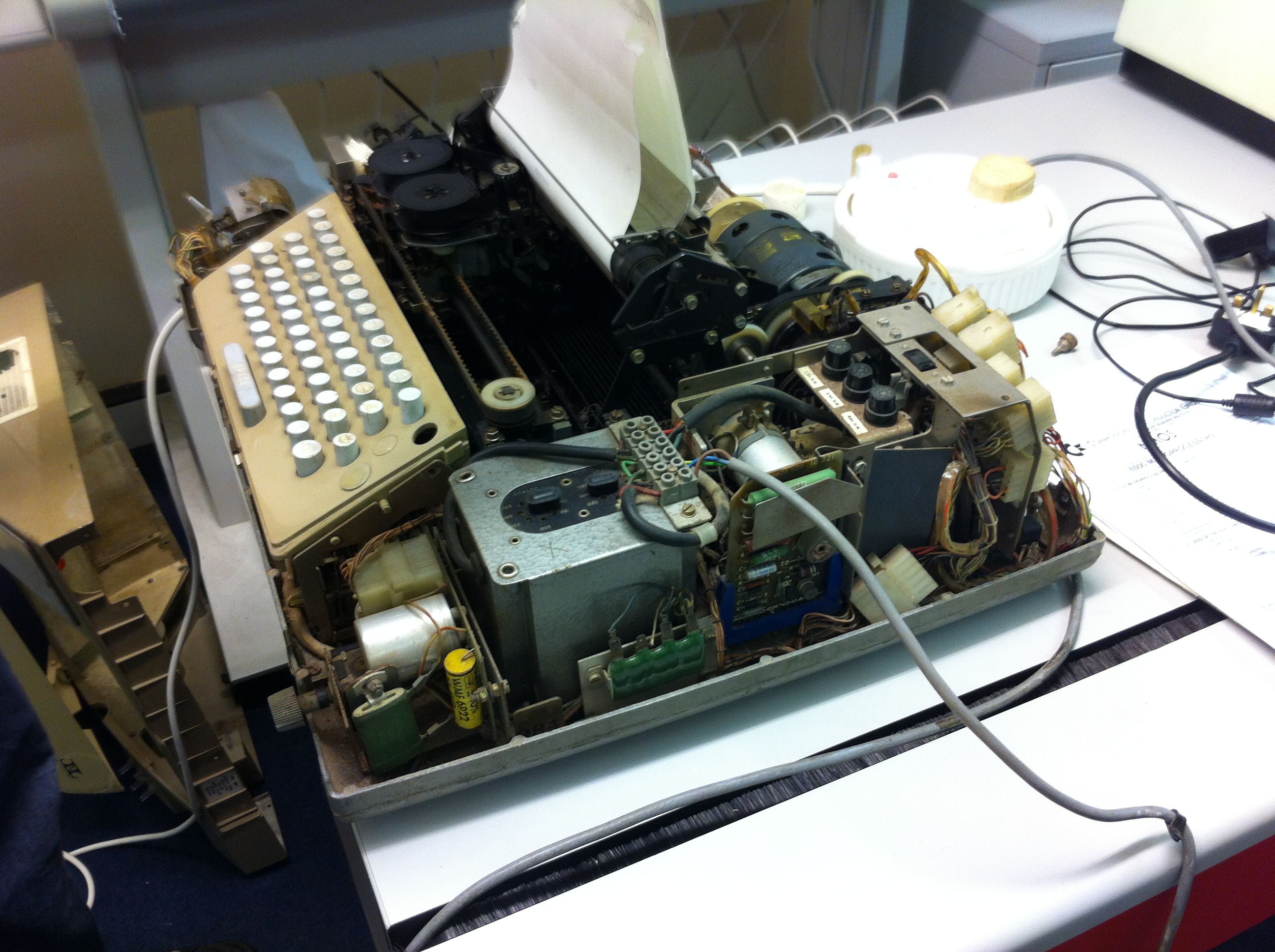
Teleprinter with the cover off
(Automatic Send and Receive), has a built in 8-level paper tape reader and tape punch.
Further overview of the ASR-33 can be found on wikipedia.
PDP 8 Online has remarkably complete documentation of the ASR-33, under Teletypes.
Because we have the case off much of the time, and because the markings on the case are a bit obscure anyway:
-
The knob on the right is master mode/power switch. Up is off, left is "local" mode, right is "line" mode. Local mode essentially transforms the asr-33 into a really expensive typewriter.
-
The vertical switch near the tape reader/puncher is the tape reader mode selector. From top to bottom: ISS 2, section 574-100-101TC
- Manual start: the reader is active.
- Auto: the reader is activated/deactivated by the computer/telegraph line.
- Manual start: the reader is deactivated.
- Free: the paper drive motor is disengaged, so the operator can move the paper to the right position.
(Note moved to here by Tony)
I came across this useful site:
http://www.baudot.net/tty-connect.htm
This suggests that we would need an 80 Volt supply to drive the currrent loop ?
Will research further.
Response from Tony: As I understand it from the Wikipedia page we need enough supply voltage to send the right amount of current to the teletype, so the voltage we need depends on the input resistance. The 80V mentioned at the baudot site would represent a limit on how many devices could be attached to that current loop. E.g. at 60mA, you could have about 13 100Ohm devices. If you had only 5 100Ohm devices on the loop then the driver would reduce its supply to 30V to keep the correct current. This explains it better. We will need to know the input resistance of the teletype to work out the voltages needed to drive the two logic levels at 4mA and 20mA (or 60mA).
Looking at the PDF for ASR33 it uses a current loop internally with a fixed supply voltage of 48V through a 750Ohm resistor to supply 64mA or 2200Ohm for 21.8mA (selected by how its wired up, so we will need to look at this on Wednesday). I assume we need to provide a similar circuit to that on page 3 of this PDF, perhaps driven by opto-isolators as suggested by Paul Stilwell and Dave Clarke.
-
Opto-isolators have been suggested as a way to isolate the higher interface voltages from the lower voltage control circuits. Mike's circuit uses an opto isolator, Tony's uses a signal controlled current source without an opto isolator.
-
Are we plugging straight into a PC or via a microcontroller? We've tried both but we're limited to a PC-with-serial-port option at the moment due to a lack of microcontrollers that can handle 110 baud.
-
What power supplies do we need? Not as high as we originally thought - a 20V supply worked with Tony's first prototype, and he's using a 31V supply at present. Not sure what Mike's circuit is using but its from a standard Wallwart.
-
Can we control the paper tape punch independently of the teleprinter? (In case we want to use it for emoticons). The documentation describes a 20-pin connector with control for printing and punching - we need to look for this on the teletype and decide whether to use it as our physical interface.
-
Which microcontroller - PICAXE, Arduino, another?
-
Do we need a PC or is it worth producing a microcontroller-only solution? The arduino could use an Ethernet shield, so we wouldn't need a separate PC.
-
Where do we get more tape from? Is it more effective to cut our own, or to buy it already in the right format?
-
The ASR-33 had an optional RS232C interface, so is one fitted? Looks like no.
-
The keyboard can be wired for even, mark, or space parity (8th bit). Which way is ours wired? These are the jumper blocks at front left and right of the keyboard. See manual pdfs part 1_2, page 12 for table, reproduced here:
option lead 1 lead 2 lead 3 lead 4 even parity on off off on 8th bit always mark off on on on 8th bit always space either on, or both off x on or off off
-
What language for the PC software - we have solutions in Java and C#. The Java code relies on the RXTX DLL which doesn't seem to work on Windows XP/Windows 7, so we'll have to stick with C# on a laptop or a Netduino/Fez Panda.
-
The Netduino/Fez Panda can go as low as 110 baud, as can a PC with a 9-pin serial port, and apparently a Psion organiser can cope with it as well.
-
Which website for the sentiment indication? We have two suggestions at present. Streamcrab and Sentiment140.
- Circuit diagrams available in this PDF. One diagram shows the internal current loop (the Local Loop) that we can either copy or tap into to get a suitable current fro driving the teletype.