APDS 9960 - stodev-com-br/tasmota GitHub Wiki
This feature is not included in precompiled binaries.
To use it you must compile your build. Add the following to user_config_override.h:
#ifndef USE_APDS9960
#define USE_APDS9960     // Enable APDS9960 Proximity Sensor (+4k7 code)
#endif
Configuration
Wiring
| Breakout | ESP8266 |
|---|---|
| VCC/VIN | +3.3VDC |
| GND | GND |
| SCL | GPIOy |
| SDA | GPIOx |
| INT/IRQ | not used |
Tasmota Configuration
In the Configuration -> Configure Module page assign:
- GPIOx to
I2C SDA (6) - GPIOy to
I2C SCL (5)
After configuring the GPIO's the driver will detect the APDS-9960 automatically. On first boot sensor will start in gesture mode. It will not appear in the webUI but it can be observed via MQTT messages in console:
21:34:21 MQT: tele/tasmota/RESULT = {"Gesture":"Off"}
21:34:23 MQT: tele/tasmota/RESULT = {"Gesture":"On"}
21:34:25 MQT: tele/tasmota/SENSOR = {"Time":"2019-10-31T21:34:25","APDS9960":{"None":1}}
21:34:26 MQT: tele/tasmota/SENSOR = {"Time":"2019-10-31T21:34:26","APDS9960":{"Right":1}}
21:34:29 MQT: tele/tasmota/SENSOR = {"Time":"2019-10-31T21:34:29","APDS9960":{"Down":1}}
21:34:29 MQT: tele/tasmota/SENSOR = {"Time":"2019-10-31T21:34:29","APDS9960":{"Right":1}}
21:34:31 MQT: tele/tasmota/SENSOR = {"Time":"2019-10-31T21:34:31","APDS9960":{"Left":1}}
21:34:33 MQT: tele/tasmota/SENSOR = {"Time":"2019-10-31T21:34:33","APDS9960":{"Up":1}}
21:34:35 MQT: tele/tasmota/SENSOR = {"Time":"2019-10-31T21:34:35","APDS9960":{"Down":1}}
When you enable RGBC mode with Sensor27 0 sensor will show up in web UI:

and in MQTT topic (according to TelePeriod):
MQT: tele/tasmota/SENSOR = {"Time":"2019-10-31T21:48:51","APDS9960":{"Red":282,"Green":252,"Blue":196,"Ambient":169,"CCT":4217,"Proximity":9}}
Commands
| Command | Value | Description |
|---|---|---|
| Sensor27 | Show APDS9960 gesture/RGBC mode | |
| Sensor27 | 0 / off | Disable APDS9960 gesture mode/Enable RGBC mode |
| Sensor27 | 1 / on | Enable APDS9960 gesture mode/Disable RGBC mode |
| Sensor27 | 2 / on | Enable APDS9960 gesture mode/Disable RGBC mode with half gain |
| Sensor27 | 3 ...255 | Set ATIME register for different integration times |
Example rules
In gesture sensing mode Tele-APDS9960 is the trigger (APDS9960 will not work)
Device will be in RGBC mode until something is close to it, then it switches into gesture mode for 60 seconds.
Rule on APDS9960#Proximity=250 do backlog Sensor27 1; RuleTimer1 60 endon on Rules#Timer=1 do Sensor27 0 endon
Relay ON when ambient light is below 100 lux.
Rule on APDS9960#Ambient<100 do POWER ON endon
Control ON/OFF, brightness and color temperature with gestures
Rule on Tele-APDS9960#Long do power toggle endon on Tele-APDS9960#Up do dimmer + endon on Tele-APDS9960#Down do dimmer - endon on Tele-APDS9960#Left do ct + endon on Tele-APDS9960#Right do ct - endon
Known issues:
-
The different PCB’s on the market seem to differ quite substantially regarding to their electrical characteristics. We have at least one case report, where this led to a malfunction on an ESP8266-board within Tasmota but in another library too. The exact technical reason can only be suspected, but it is probably related to electrical noise and/or power consumption.
In the case from above the sensor measured an incorrect high proximity value, which resulted in repeated triggering of a "LONG" gesture. The solution was to decrease the gain factor for proximity and gesture. Therefore the argument 2 (sensor27 2) was introduced to change this at runtime.
If you experience gesture sensing problems you could try this out, but if you measure proximity values <25 with nothing in front of the sensor (e.g. web interface aftersensor27 0), then there is very likely another problem. It can be assumed, that the gesture sensitivity will suffer with reduced gain, so first try option 1 (=default).
Beside that better wiring and maybe an additional capacitor over VCC and GROUND might be helpful. -
The measurement of the light level is briefly described in the datasheet and the open-source-libraries use the ambient-light-value directly from the sensor or calculate a LUX-value from RGB. Both variants are usable and differentiate between low and strong light, but the absolute values are questionable and at the moment we have an uncalibrated sensor.
All known solutions use a fixed integration time, which is more or less the same as a fixed exposure time in photography. In contrast the TSL2561-library uses various integration times and maybe this is possible on the APDS9960 too.
To eventually achieve this in the future, the option to set this integration time at runtime was added. Every argument between 3 and 255 sets the ATIME-register.
The formula is: integration time = (256-ATIME)*2,78 ms, so with the default value of 219 we get (256-219)*2,78 = 102,86 ms. That means a smaller ATIME makes the integration time longer and more photons are captured, which might be usable for (very) low light conditions, because otherwise the sensor will saturate too early. The opposite is valid for a bigger ATIME value.
The change of this value only makes sense for: users who need to change the sensitivity, if the sensor resides behind dark glass or want to contribute to the development of a new LUX-calculation in the driver. If we get enough feedback, this could lead to an improvement on the software side. Feel free to open (or search for) an issue, if you have measured the APDS9960 against other devices with different ATIME-values at different light levels. This is not a trivial task though.
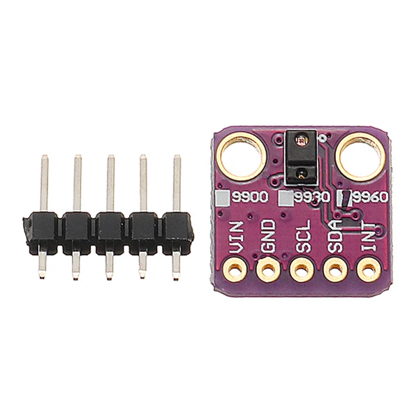
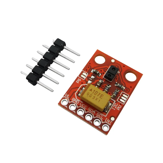
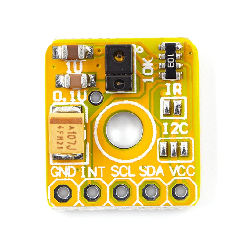
Generally available types of breakout boards


Where to get
- ~ 2€ at AliExpress
- ~ $8 at Adafruit