BME280 - stodev-com-br/Tasmota GitHub Wiki
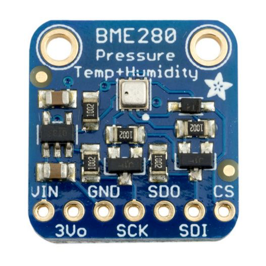
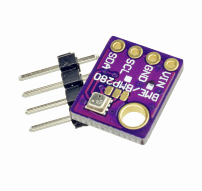
BME280 sensor, an environmental sensor with temperature, barometric pressure and humidity" See BME280 Temperature, Humidity and Pressure Sensor for more information.
BME280 driver also supports BMP085, BMP180 and BMP280 sensors.
| BME280 | ESP8266 |
|---|---|
| GND | GND |
| VCC | 3.3V |
| SDA | GPIOx |
| SCL | GPIOy |
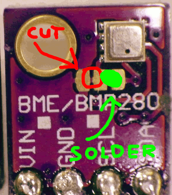
If you are using breakout boards which break out pins CSB please ensure that you connect this pin to VCC to ensure that the chip stays in I2C mode. This is due to some manufacturers of breakout boards add pull-up resistors to allow for SPI compatibility (some would default to SPI, others to I2C)_
Connect the SDO pin to GND or VCC to ensure required I2C address is used by the chip - Again some manufacturers add resistors to provide external bias but due to them wanting to retain SPI compatibility such pulldown resistors may not be sufficient to ensure that the pin levels are at the correct transition during power-up / reset state._
Since the chip supports both SPI and I2C, but in Tasmota only I2C is supported you want to make sure that the chip is in I2C mode during reset/power-on and remain in that state during operation otherwise unexpected behaviour may result when the Tasmota firmware polls the chip for sensor data.
After a reboot the driver will detect BME280 automatically and display temperature, humidity and pressure measured.

Sensor sends a tele/%topic%/SENSOR JSON reponse:
{
  "Time": "2019-11-03T19:34:28",
  "BME280": {
    "Temperature": 21.7,
    "Humidity": 66.6,
    "Pressure": 988.6
  },
  "PressureUnit": "hPa",
  "TempUnit": "C"
}
From v6.1.2.20 you can use multiple BMP Sensors (#4195)
Limit is 2 sensors and you have to change the address of one sensor.
Than connect your sensor SCL and SDA parallel to the device.

BME280 address change example:

TempOffset can be used for calibrating the measured temperature. This setting affects all temperature sensors on the device.

