Customizing the Display - sparkfun/Serial7SegmentDisplay GitHub Wiki
The Serial 7-Segment Display is driven by an ATmega328, which makes it very compatible with the Arduino IDE. It's also got a serial bootloader, and an FTDI header, so you can use an FTDI Basic or FTDI Cable to program it. We're hoping to make customizing the display's firmware as easy as possible, this page will cover everything you need to do so.
In order to program the display, you'll first need to download Arduino. Go to the Arduino download page and grab the most recent version. Follow their directions for unpacking and installing the IDE.
Once you've got Arduino downloaded and installed, there's one more step required to use the S7S - installing the addon. The addon adds a Serial 7-Segment Display option to Arduino's Tools > Board menu.
Paste https://raw.githubusercontent.com/sparkfun/Arduino_Boards/master/IDE_Board_Manager/package_sparkfun_index.json into the Additional Boards Manager URL in preferences. Then use Tools > Board > Boards Manager to find the Serial 7-Segment Display board and click Install
You must install the board manually. In the firmware folder of this repo, there's a hardware directory. That directory should be placed in your Arduino sketchbook. Where's your Arduino sketchbook? Well, by default, it should be an Arduino folder in your home directory, but to double-check you can go to File > Preferences within Arduino and see the Sketchbook location text box.

Recent versions of the Serial 7-Segment Display firmware use the SevSeg library to control and update the display. You can find the most recent version of the library at it's github repo page.
Make sure you install the SevSeg folder in the libraries folder in your Arduino sketchbook.
The S7S's FTDI header is on the left side (if you're looking at the display, right-side up) of the board. The 6 pins required to connect are faintly outlined by a white line. You can flip the display over and the 6-pins required more clearly - they go from the - pin to the DTR pin.
Either an FTDI Basic or FTDI Cable will work to upload a sketch to the display. Match up the labels on your FTDI device to those on the S7S (note the green wire on the FTDI cable is DTR, black should go to -).
Note that the FTDI basic/cable can also supply power to the display.
If you want to practice, try loading the code from the Serial7SegmentDisplay/firmware/Serial 7-Segment Display/Serial_7_Segment_Display_Firmware directory. The main part of the source code is the Serial_7_Segment_Display_Firmware.ino file. Open that in Arduino.
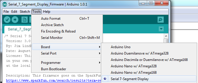
First, you'll need to select Serial 7-Segment Display from the Tools > Board menu. This was added when we installed the addon in the first step.
Then you'll need to select your FTDI board's serial port, under the Tool > Serial Port menu.
Now all that's need is to Upload the code.
Say, for instance, you wanted the display to show a 10-bit ADC reading, rather than serial data received.
You could replace the entire loop() function with:
char analogChars[4];
void loop()
{
  if (!(millis() % 10))  // update adcReading 100 times a second
  {
    int analogReading = analogRead(A7);
    sprintf(analogChars, "%4d", analogReading);
  }
  myDisplay.DisplayString(analogChars, display.decimals);
}
That'll read the ADC on A7, and print out a value between 0 and 1023 to represent that reading. It updates the reading every 10ms.
So, hopefully that gives you an idea of what modifying the firmware looks like. We've tried to make the code as easy-to-modify as possible.
- Datasheet Homepage
- Hardware Specifications - Electrical characteristics, voltage ratings, current usage, timing
- Interface Specifications - UART, SPI, and I2C explanations
- Basic Usage - Displaying Numbers and Characters, Clearing, Cursor Control
- Special Commands - Reset, Decimal, Cursor, Brightness, Baud, TWI address, and Individual segment control
- Arduino Examples - Example Code for SPI and I2C